For a long time I wanted to build a larger 3D printer “in my own way” which wouldn’t cost me very much – I mean that cost of it shouldn’t cause my wallet to “implode”. I haven’t found any 3D printer that is available on the market that would fit my needs in every aspect . Of course, there are big well-made printers on the market but their prices are enormously high.
Building and designing this printer took about half year mainly due to the lack of free time – if I could hurry up I would finish it in about two weeks.
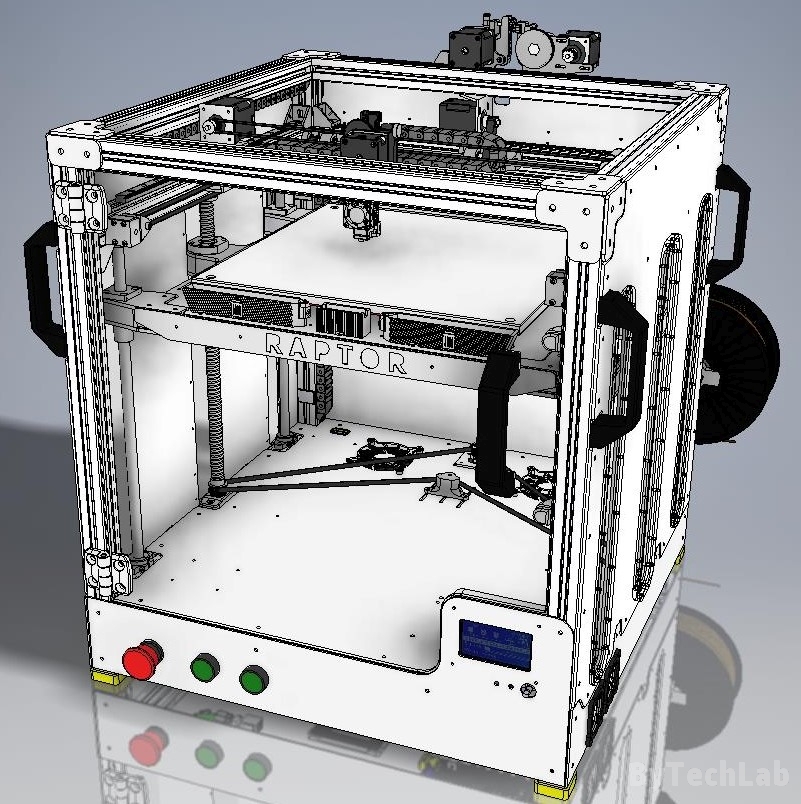
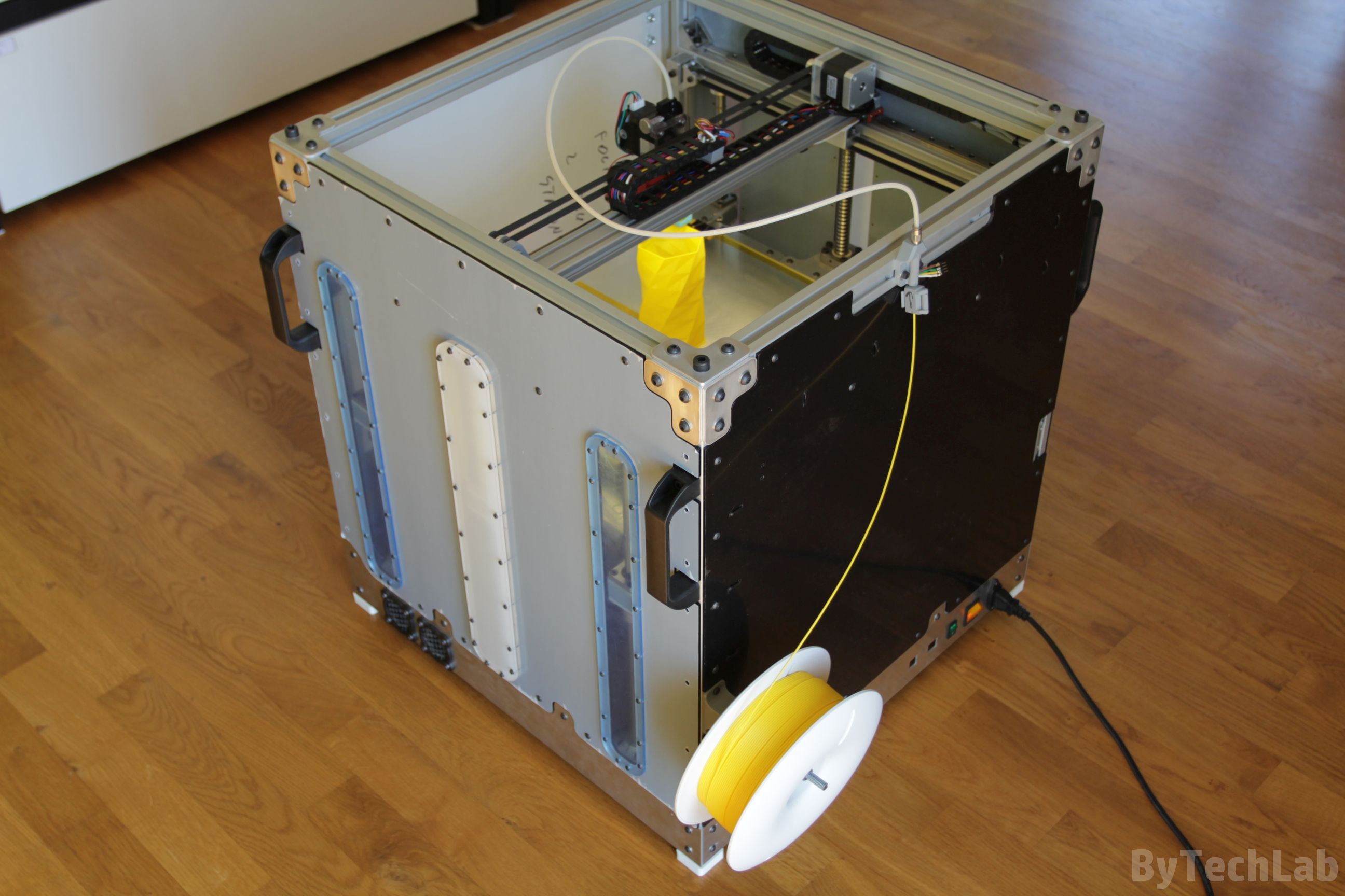
I called this printer “RAPTOR XLS 360” because this name seems to be quite unique (it’s associated with dinosaurs of course 😉 ).
The printer is not 100% finished, there are still a few small parts missing. However, I think that at this point i can describe the printer and its assembly process. Below I will show you how I’ve made this printer from an idea and design to a assembled and working printer in an short “work log-style” article. As always I’ve uploaded lots of photos .
Design
The design of the entire printer was created in the Autodesk Inventor software. The whole printer design process together with the simulation of kinematics and checking the correctness of the project took me about 2 weeks. I started the project from a few quick sketches with a pencil on paper. Then I’ve determined the general dimensions of the whole printer. Just after that I’ve started drawing individual parts.
Firstly , I had to determine the size of the printing volume around which the entire printer will be built. I decided to choose a 360 x 360 mm build area (X/Y). Why? The answer to this question is very simple – I had linear rails of this length 🙂 . The CAD project includes all real parts without basic components such as screws and washers.
The hardest thing to do was to draw the Z axis platform assembly in the way it is rigid enough. It wasn’t a easy thing because I had to deal with such a large build area. After finishing main frame assembly , I made some measurements of it and then I’ve maximally “shrunk” the frame on the Z axis platform.
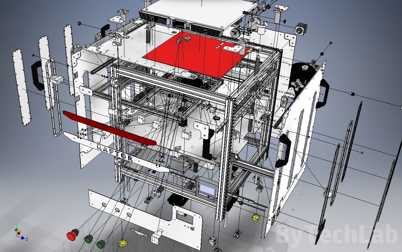
Additionally, I’ve redesigned other components in the way that they fit to the rest of the assembly. Once the key dimensions were known, I’ve designed other important parts (aluminium sheets, plexi panels, X-axis, etc.). The entire frame is based on 30 x 30 mm aluminium extrusion profiles. There are additional parts in this project which are currently missing on renders because they are not installed in printer – I will write about these parts later.
Main frame assembly
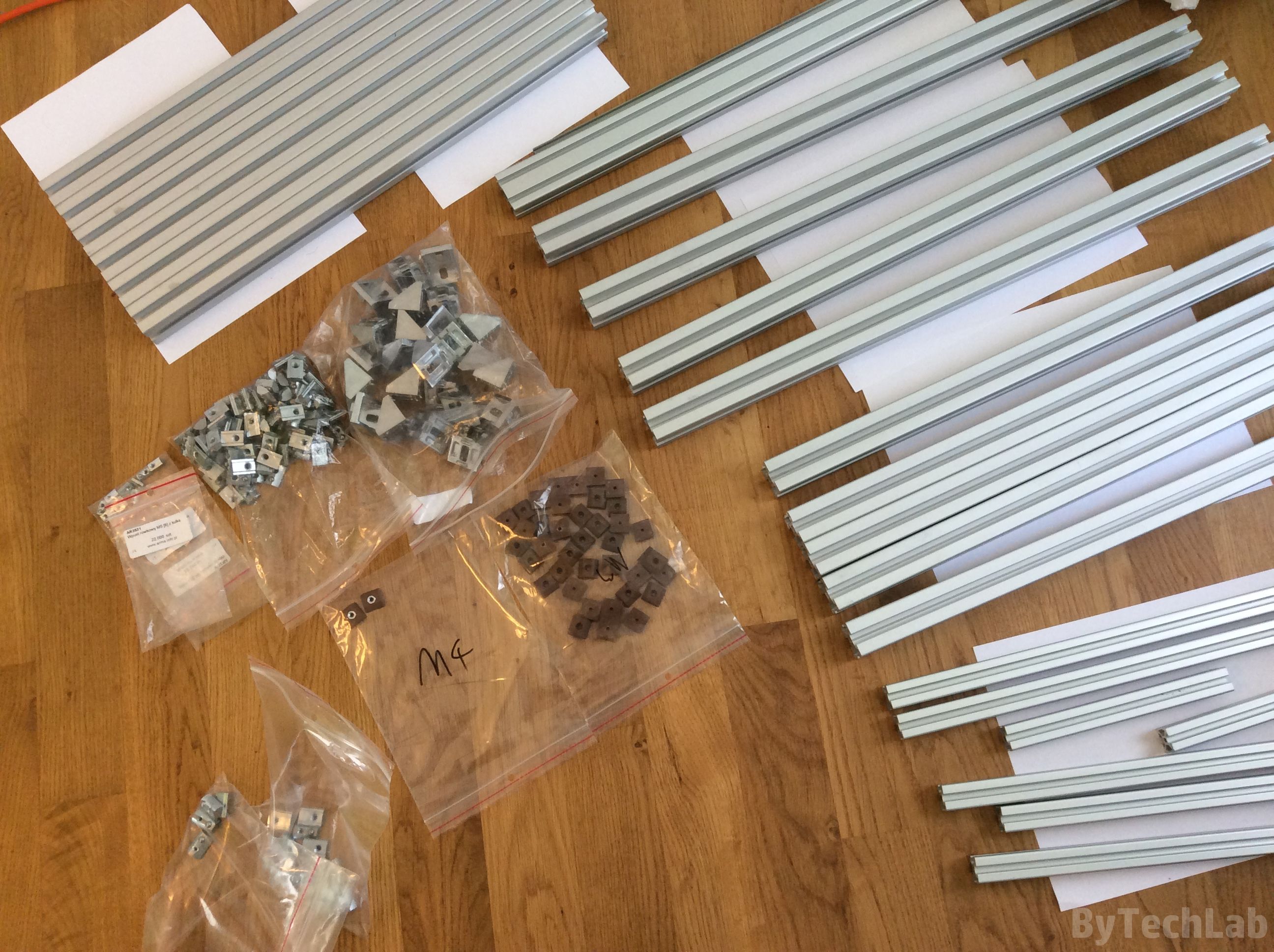
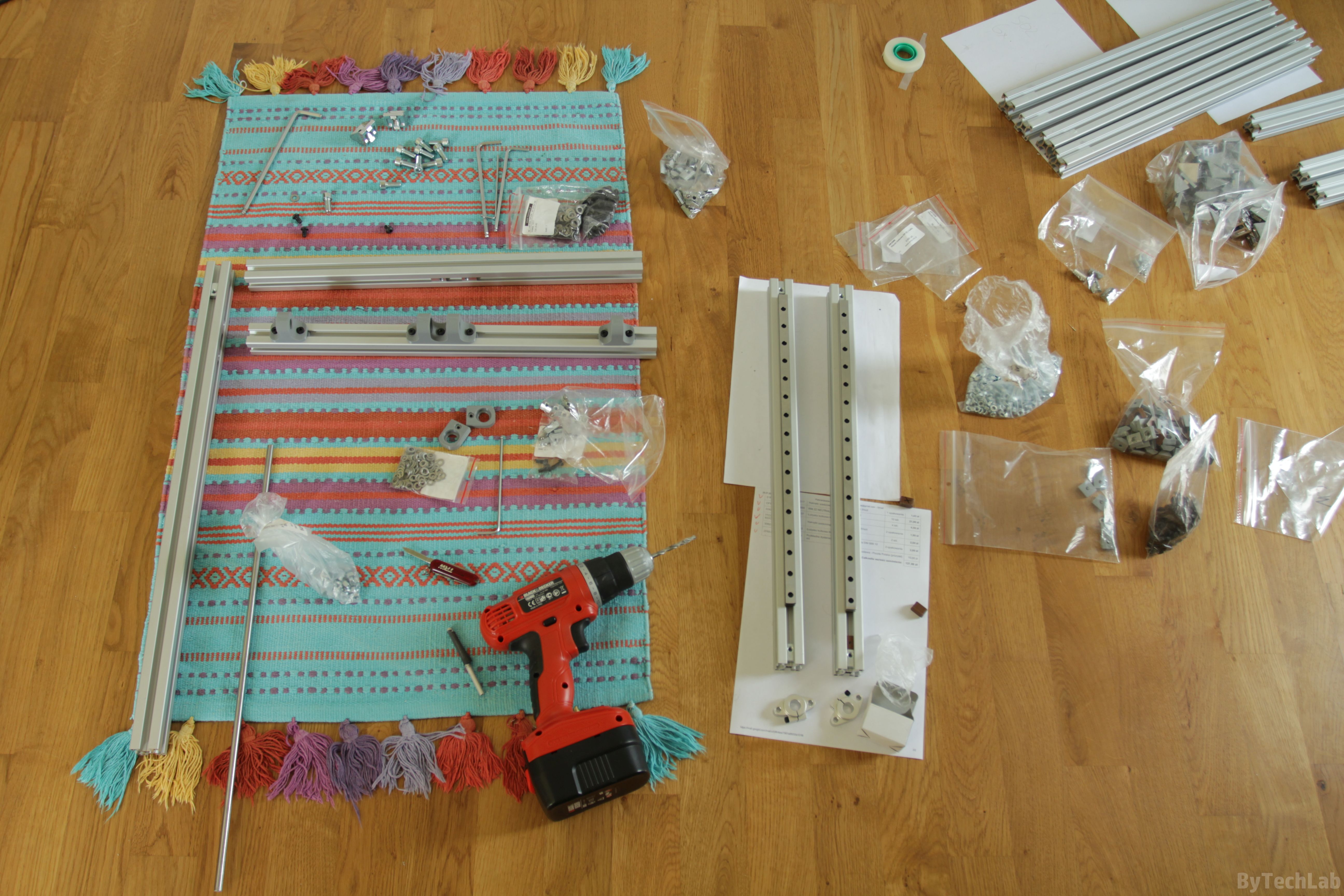
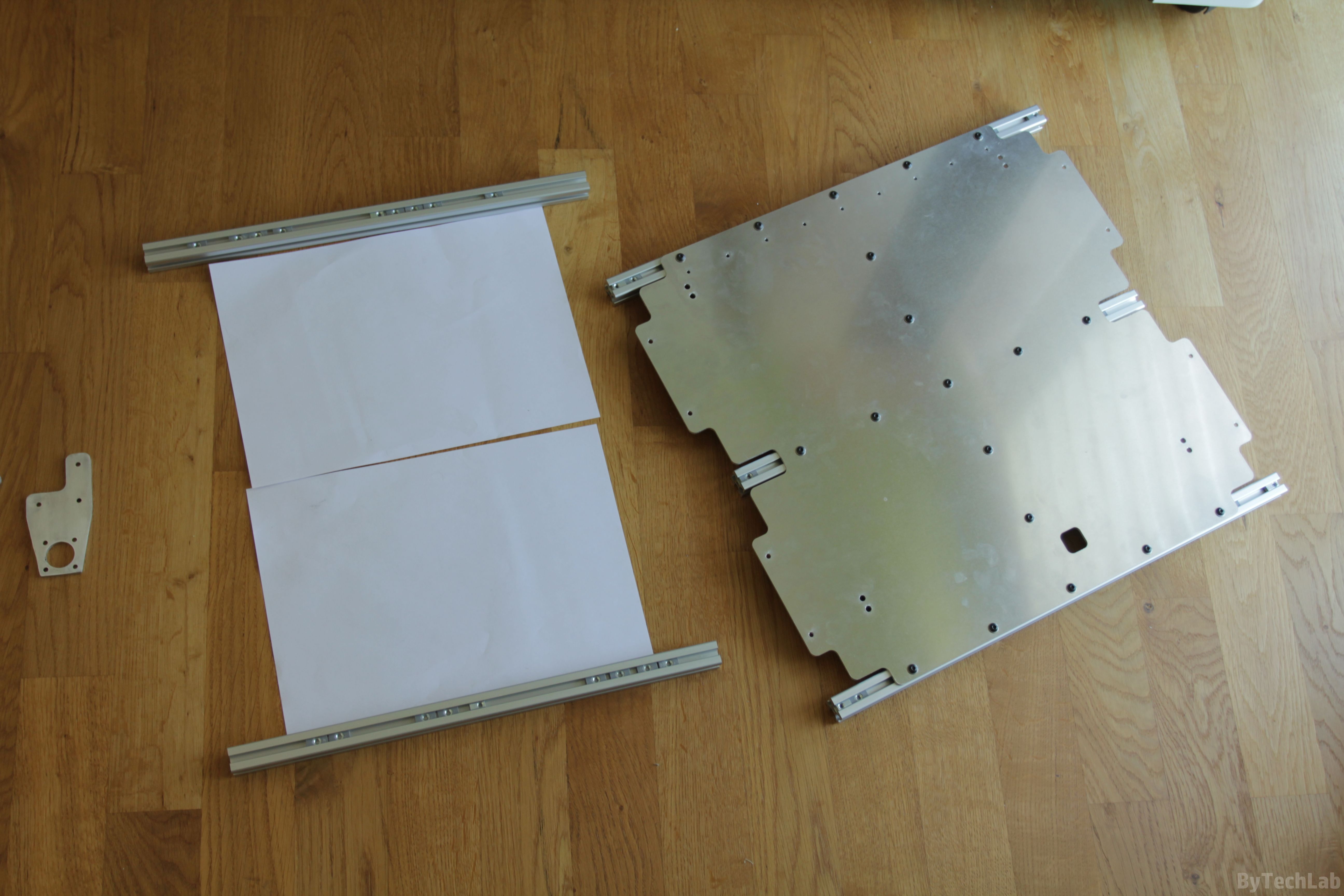
At the beginning I’ve collected all the necessary parts so that I could start to assemble the whole frame. As you can see in the pictures above there are very many parts from which the printer will be built of .
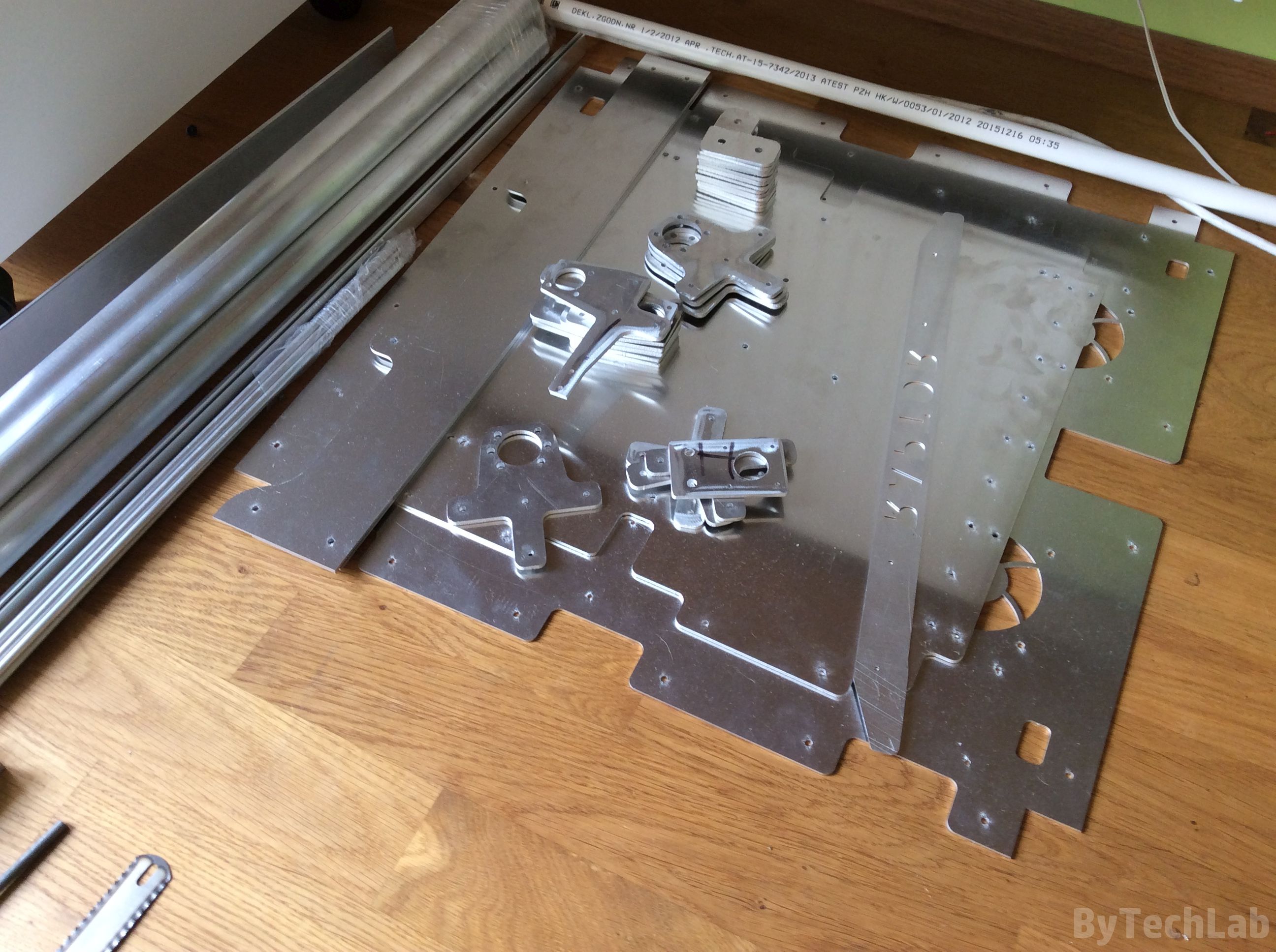
All aluminium and steel sheets/plates used in this construction were laser cut. Aluminium extrusion profiles were cut in “external company”. Unfortunately,I had to cut out some parts from standard aluminum profiles by myself because some dimensions needed to be within tolerances (I don’t have almost any experience with designing parts for bending on the press). Apart from a few minor incidents, the frame was assembled without problems.
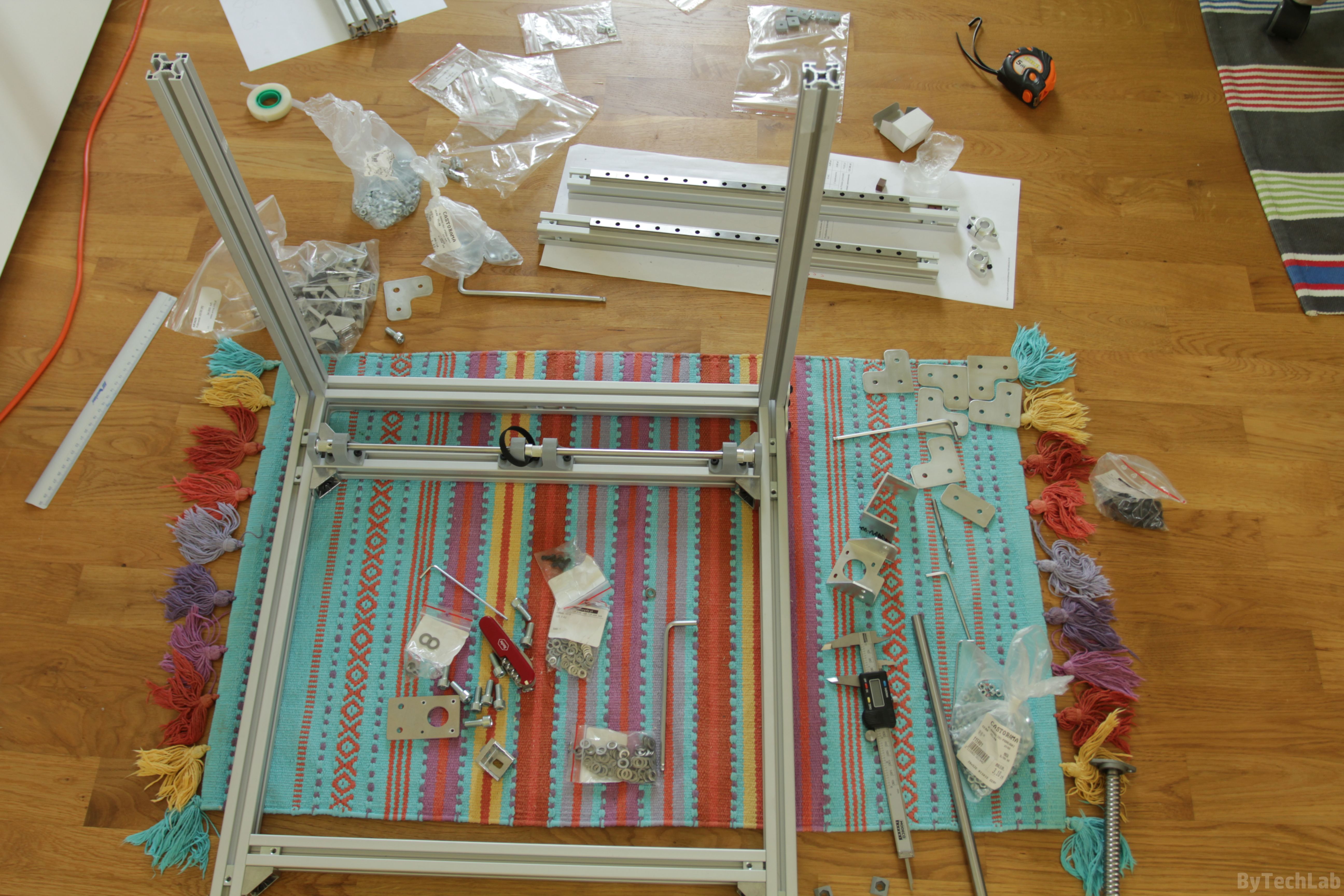
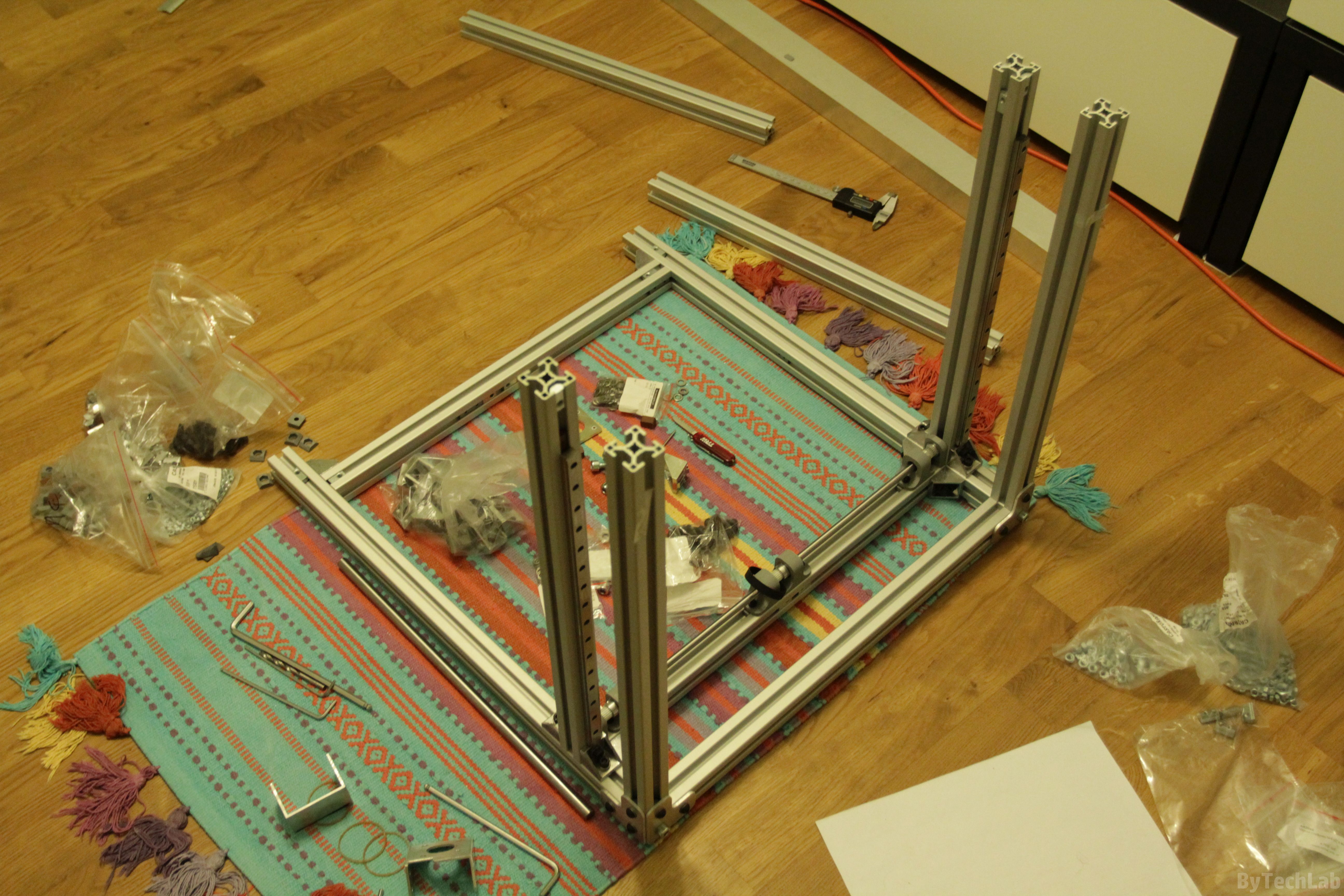
Then I’ve started assembling the whole frame, it was one of the most difficult tasks because it is not so easy to keep the right geometry within design specs. In addition, one of the aluminium extrusion profiles was unevenly cut, it was undersized by about ~ 0.3 mm. Because of that I had to move it down where it’s size is not very important and can be easily corrected.
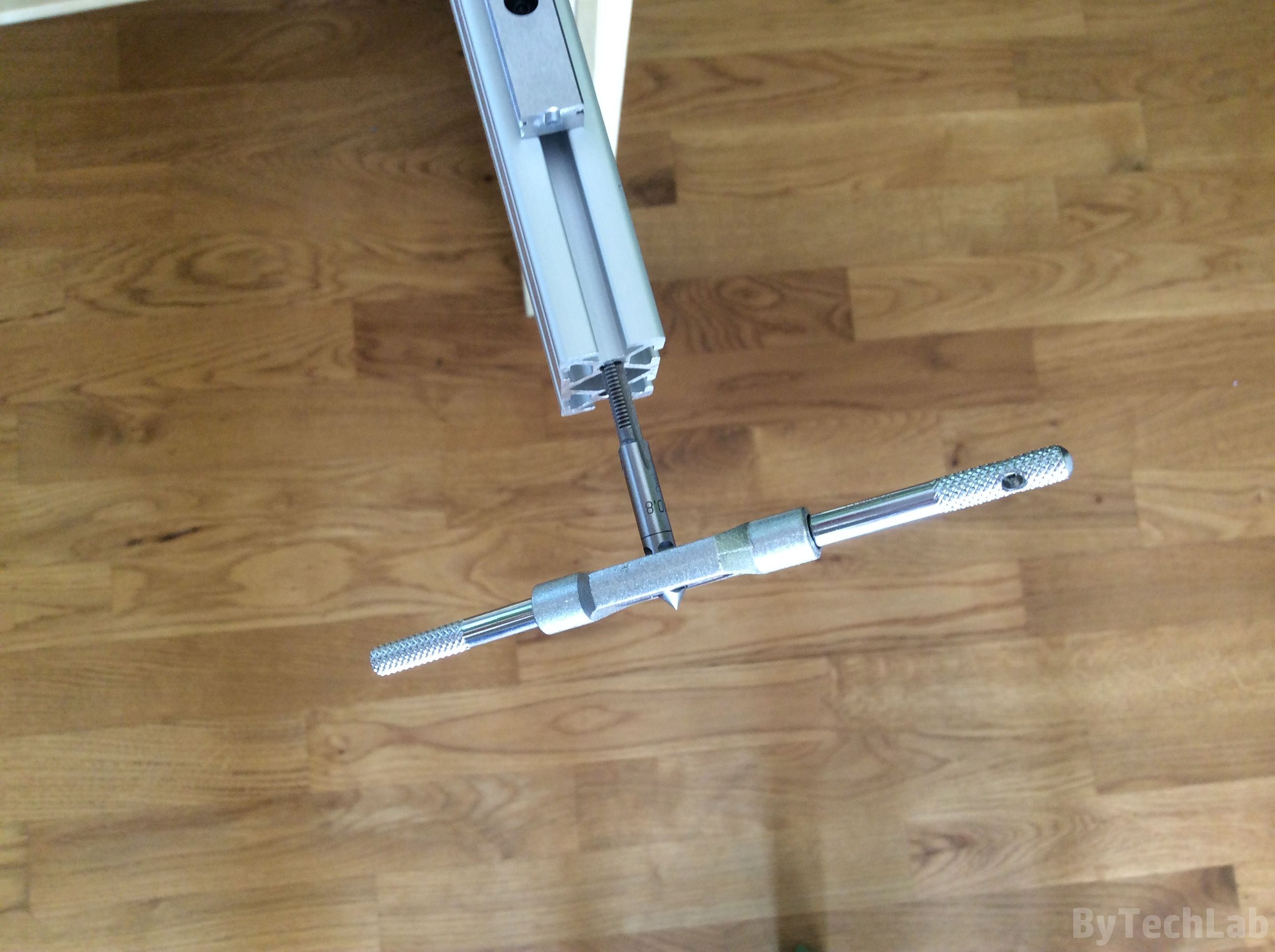
Profiles were positioned with use of reference aluminum angles and basic measuring tools such as caliper,dial gauge and gauge block’s. One of the most important tasks was to properly position the shaft responsible for driving the Y axis. The whole process was quite slow because each dimension was checked several times to make sure that everything is correct.
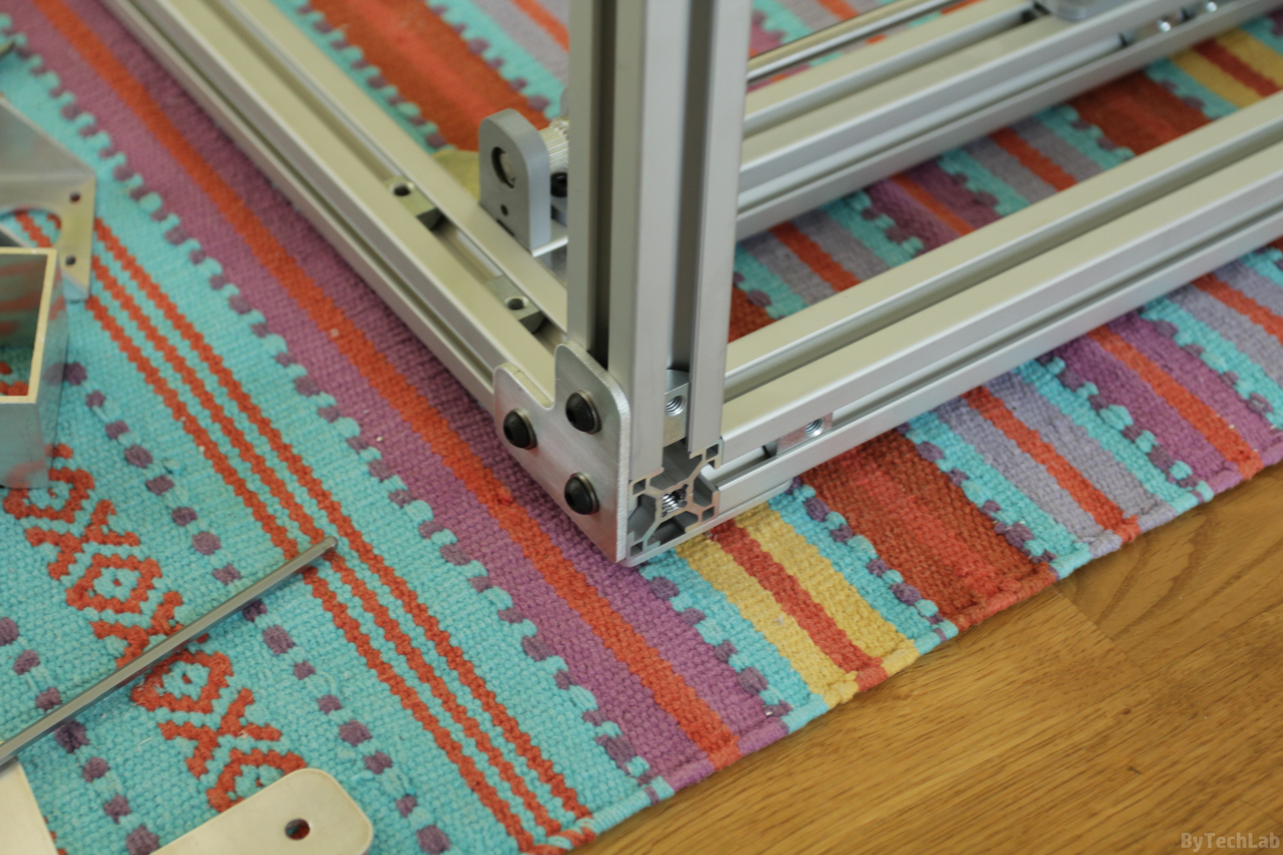
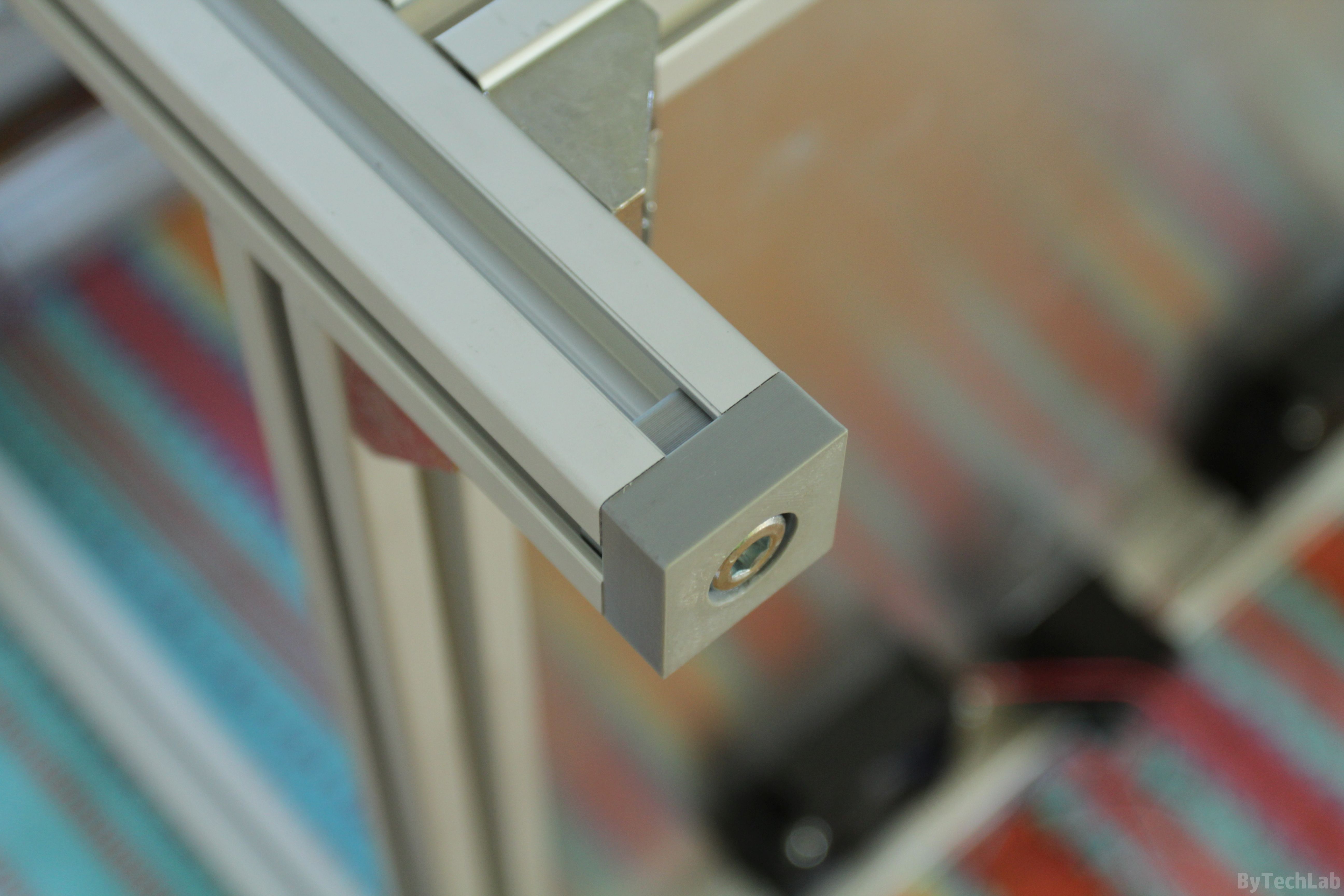
The corners of the frame are joined together with use of 3 mm thick aluminum brackets. They are very flat so,it was relatively easy to get a good perpendicularity of the joined profiles. Each bracket is bolted to 3 steel T-slot-nuts but one of them has an additional bolt screwed in to threaded main hole in one of the aluminium profiles.

Brackets which are used to join the corners have been carefully sanded using high grit sandpaper in order to make them totally flat. In addition, the edges have been deburred with a file (the laser usually leaves melted material on the edges when cutting aluminum).
The bottom plate has also been sanded in the same way to get a nice matt surface. After sanding, the bottom aluminium sheet was bolted down to the frame. In the picture below you can see how the whole frame looks after a few days of assembling. I’ve installed a legs printed form ABS filament to the printer frame. I’ve also applied a rubber dampers to these legs. All holes which had to be threaded were threaded by hand.


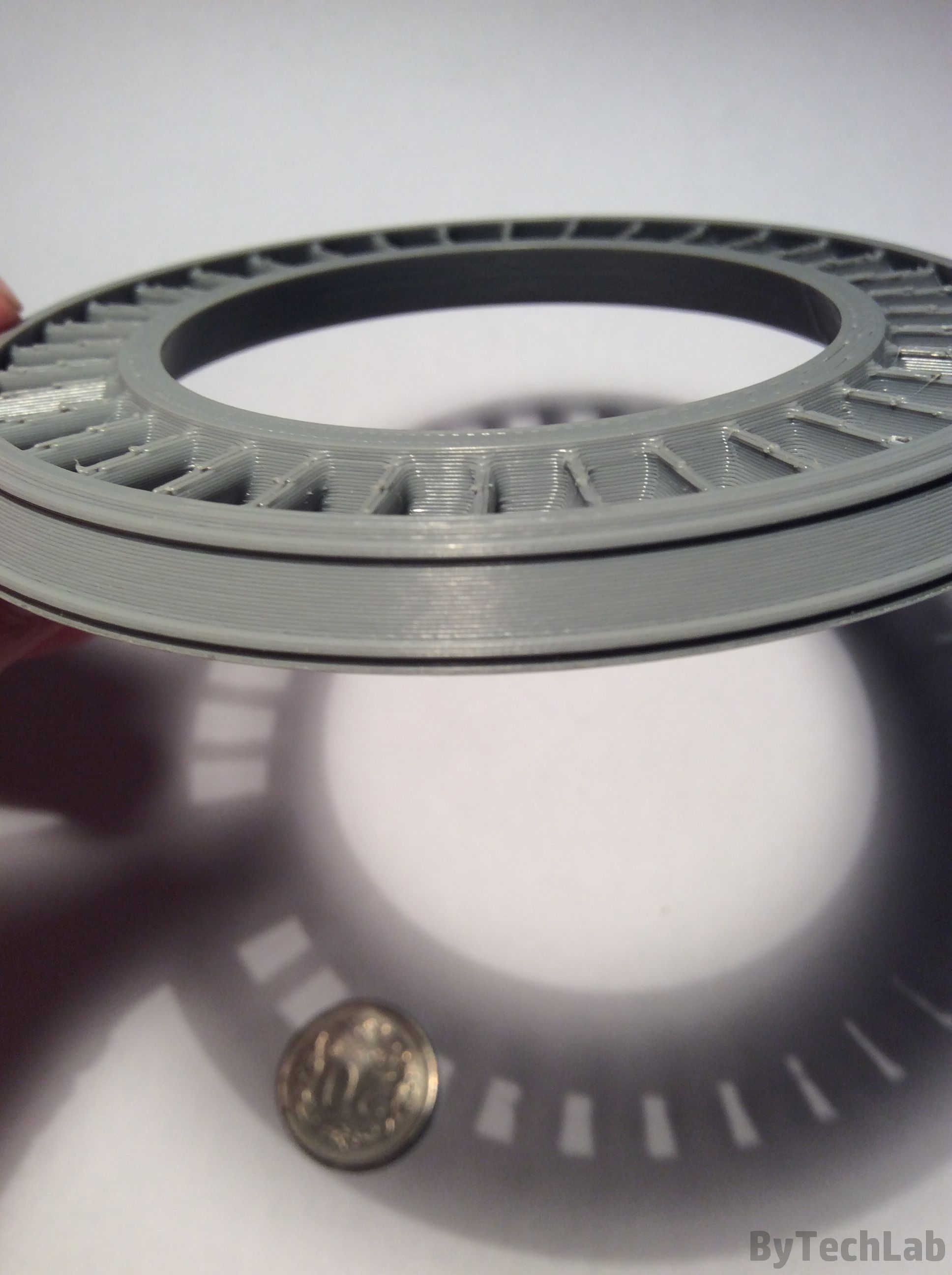
Heatbed
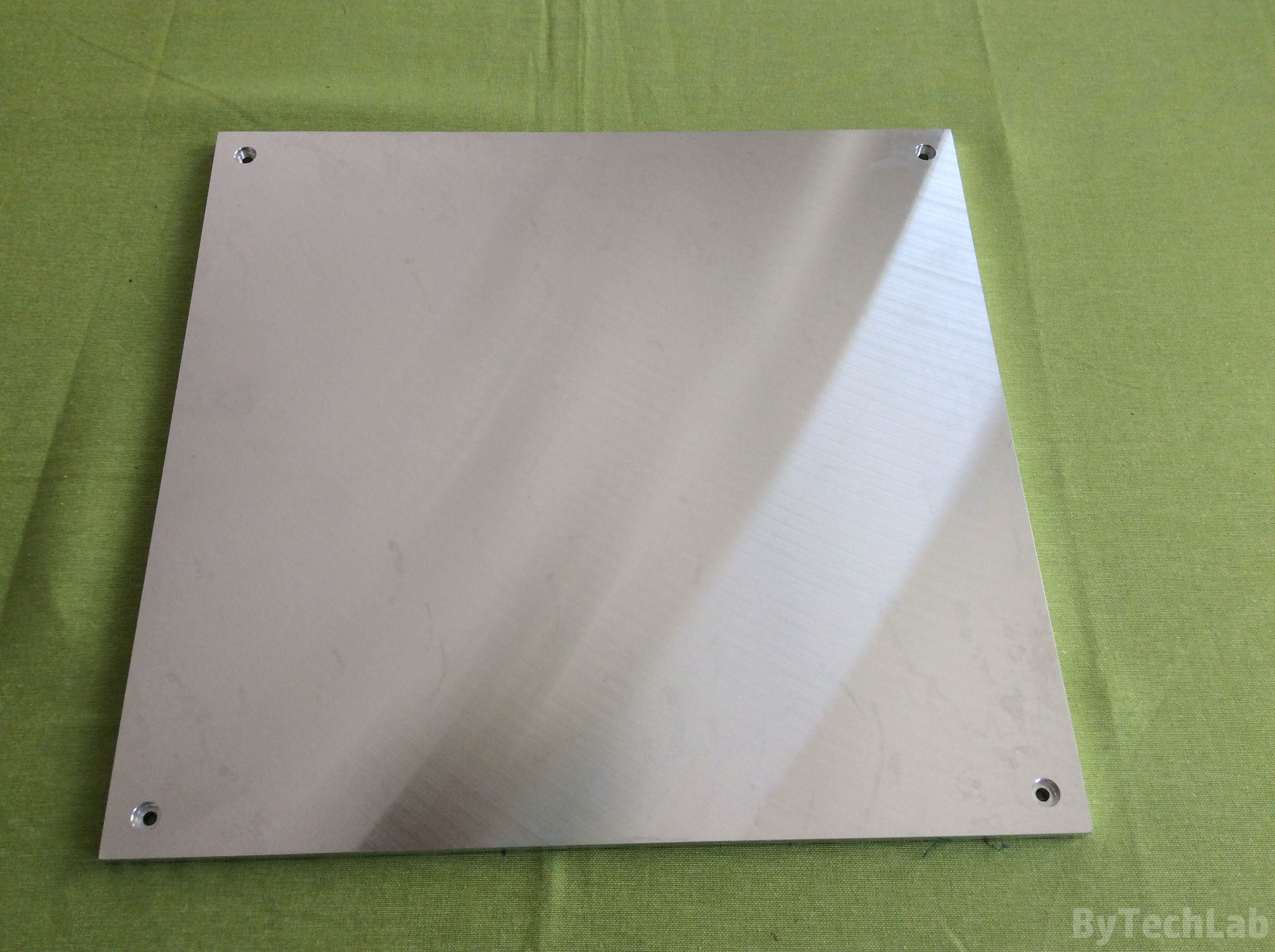
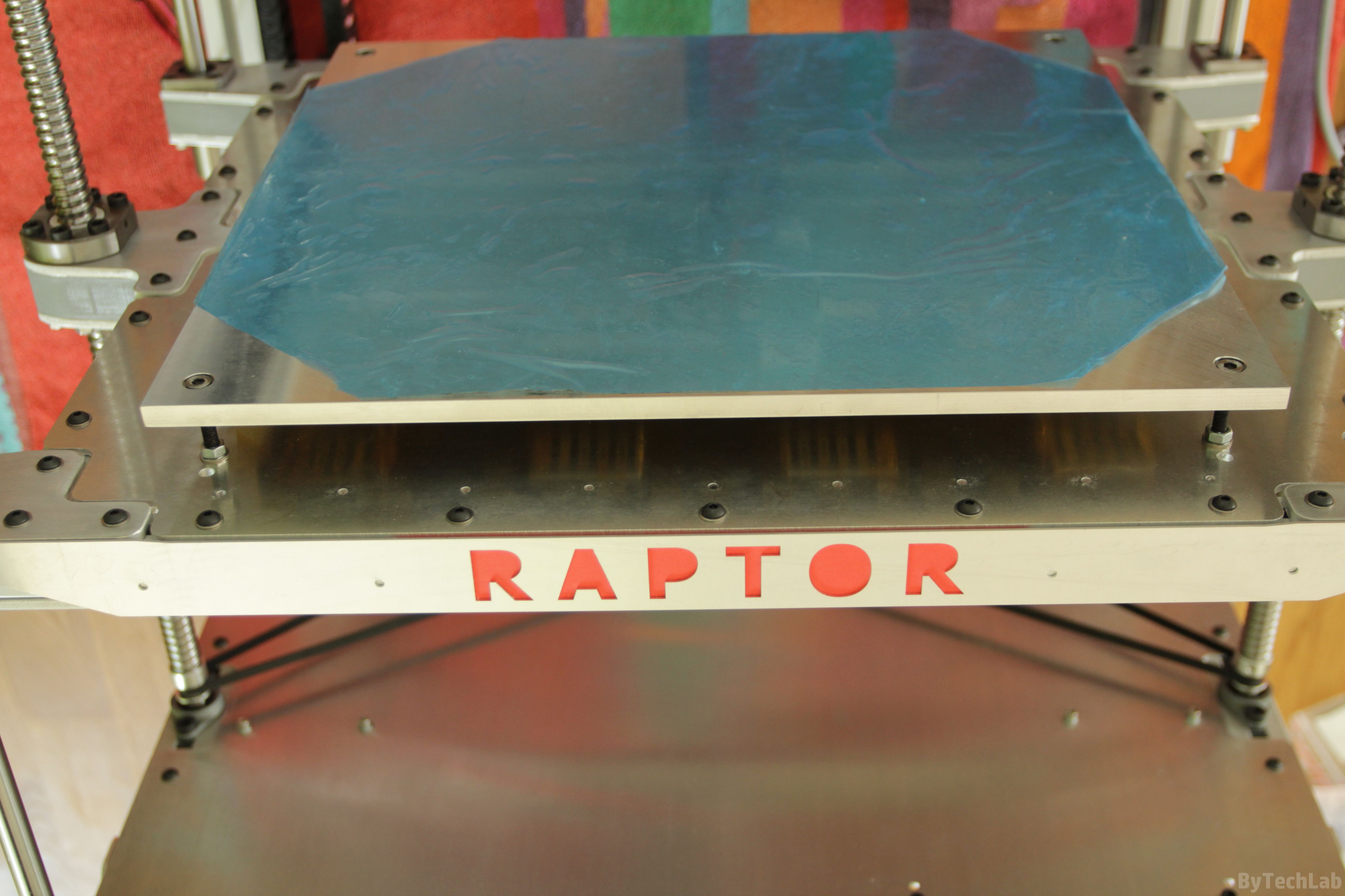
Heatbed was machined from a high flatness aluminum plate that has a thickness of 8 mm. It may look like a total “overkill” but in reality it’s not. Heatbed is incredibly flat. In order to prevent stress or bending during heating, heatbed is bolted down to the Z axis platform in the way it can expand freely. I am very pleased with this heatbed – the distance of the nozzle from the table was adjusted only once after the printer was assembled.To this day everything is nicely leveled on the entire surface. The printer is free from autoleveling or other gadgets that hide the real problem.
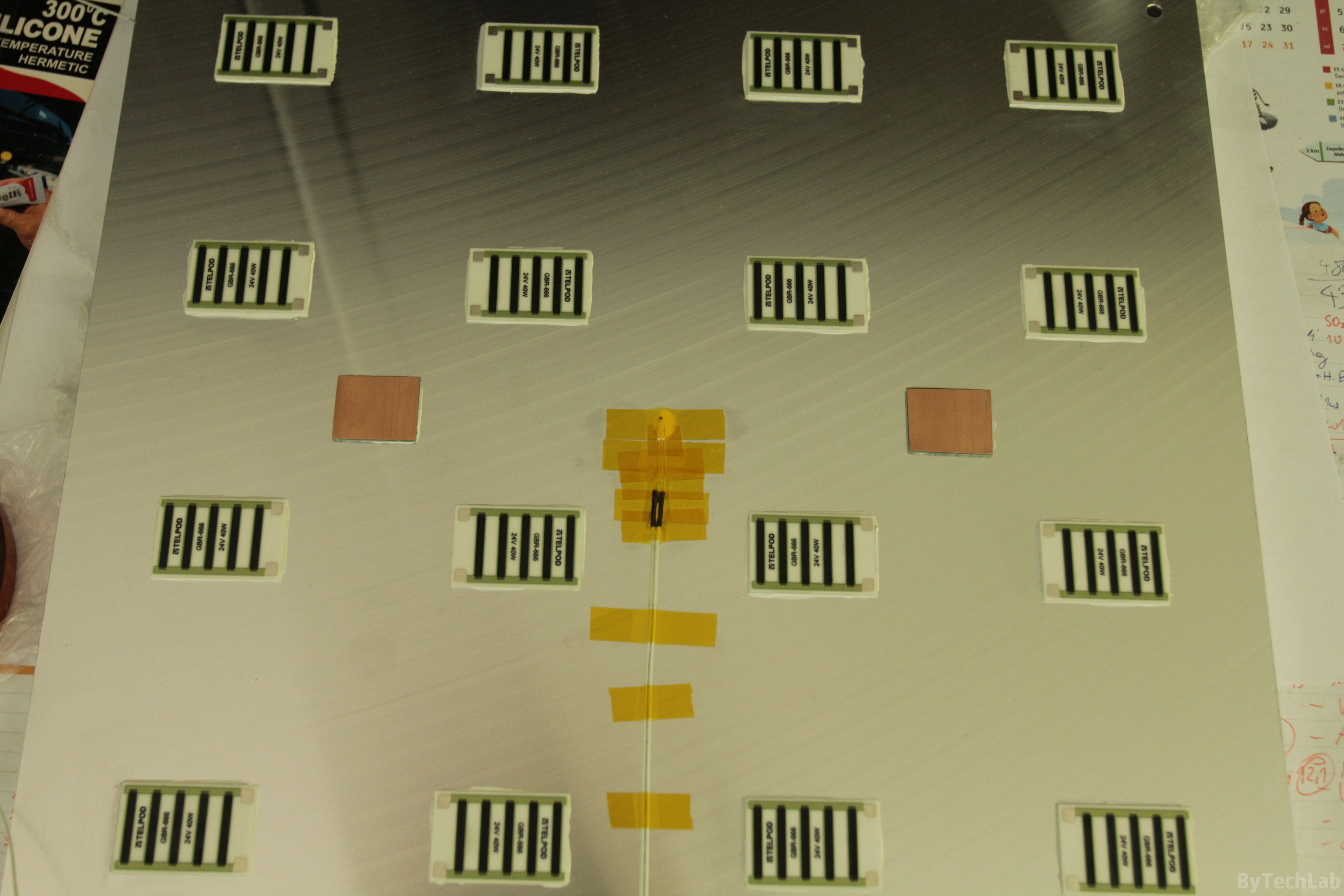
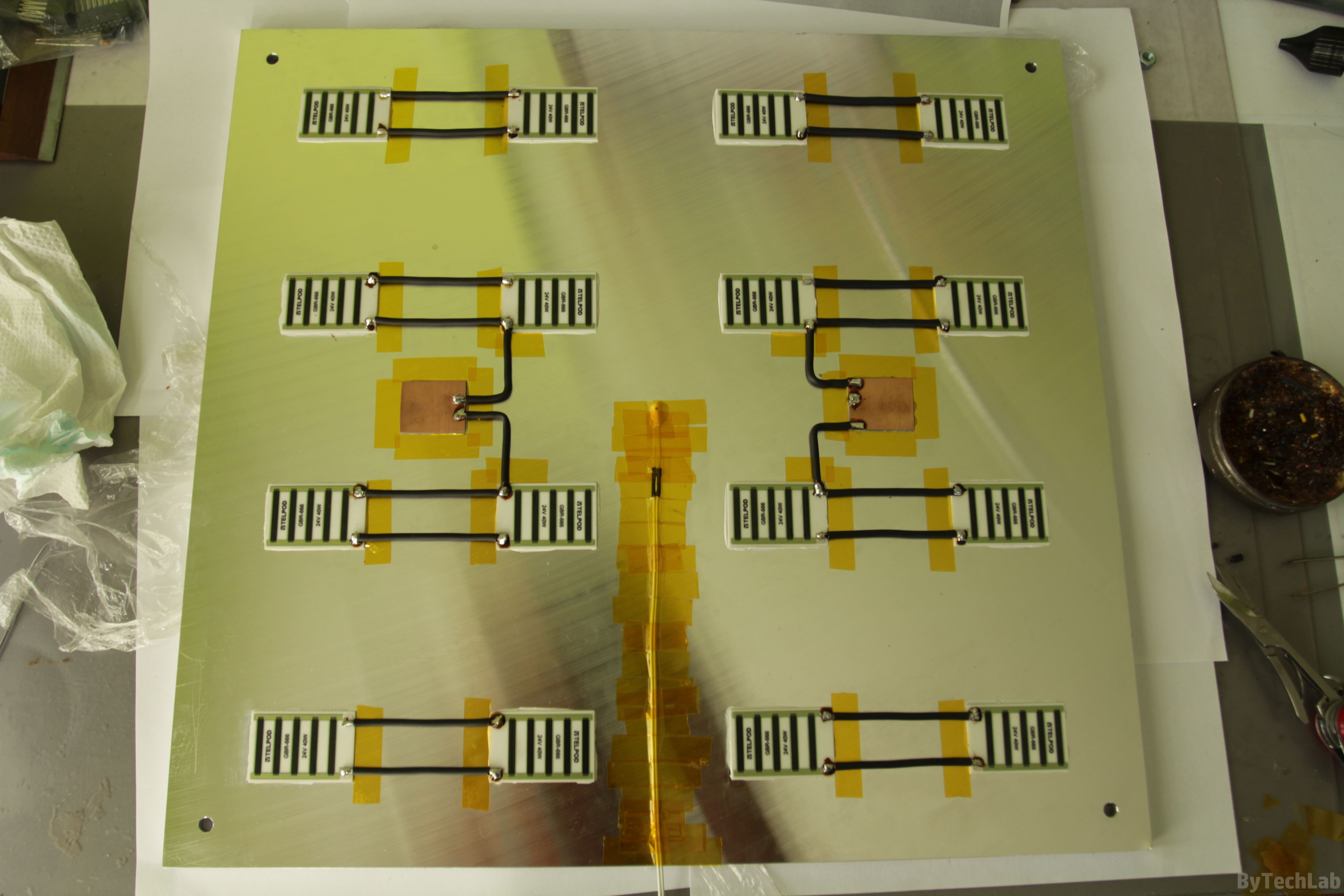
For heating the bed I used 16 GBR-666 ceramic heating/power resistors for 24 V, 40 W each. Together, this gives a power of about 640 W, which gives a total current of 26 A. The resistors were connected in parallel and glued to the table in the way the bed is evenly warmed up. The power is supplied to the table with thick silicone wires.
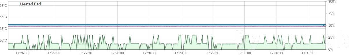
The thermistor, like the resistors, has been attached to the table with thermal conductive adhesive. I needed to tin these resistors before gluing them to the heatbed (thick aluminium plate will sink all the heat from the soldering iron due to high thermal capacity). In addition, all wires are protected and insulated with a Kapton tape. With a slightly reduced power (I don’t want to heat it too quickly) heatbed heats up to 100 degrees in a few minutes. I have attached a 2 mm thick float-glass to the top of it (I don’t want to destroy such a beautiful shiny surface 🙂 ). Thanks to high thermal capacity of this heatbed after reaching the temperature set point, it is very stable at a given level (below you can see temperature-stability chart).
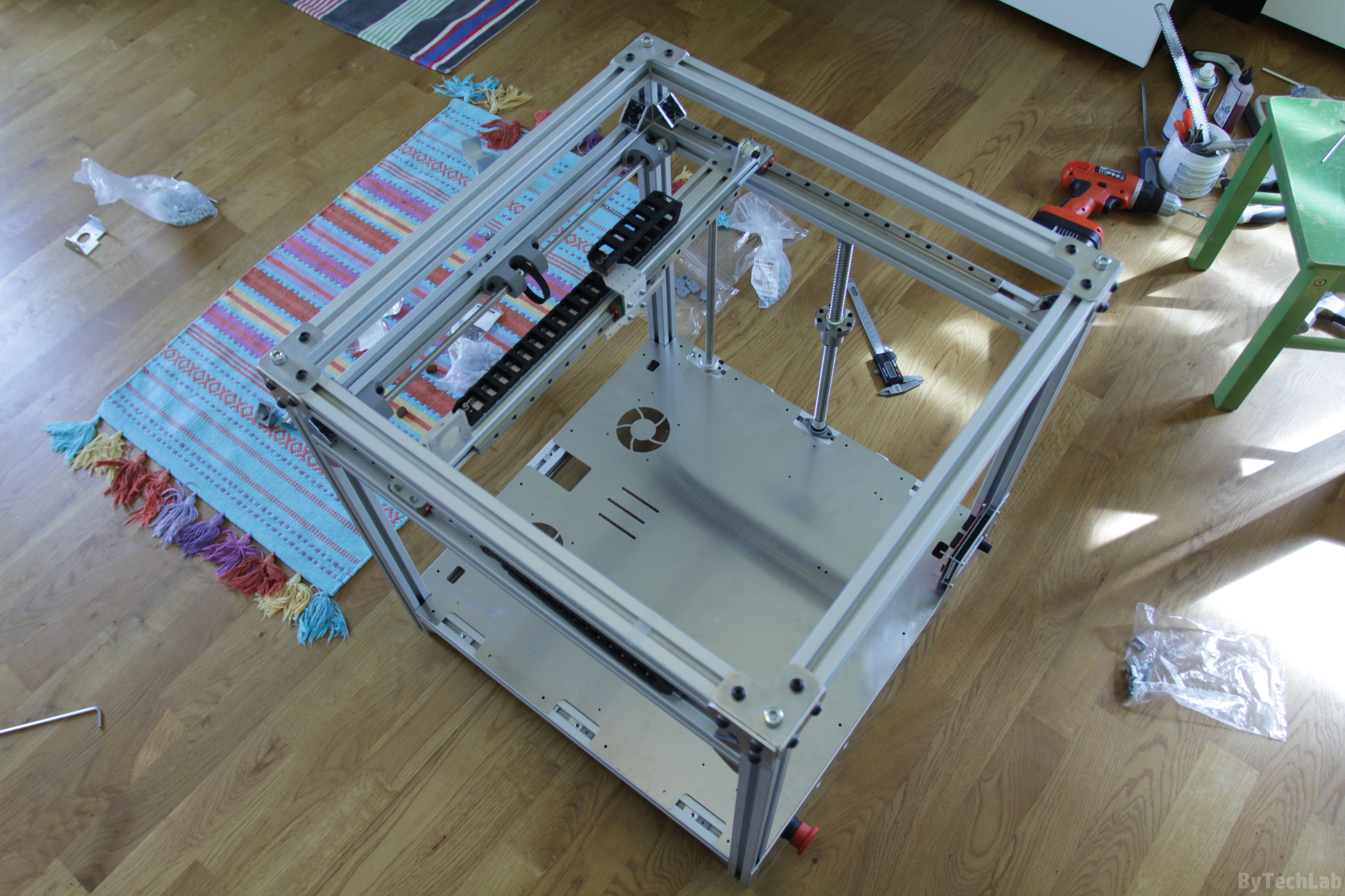
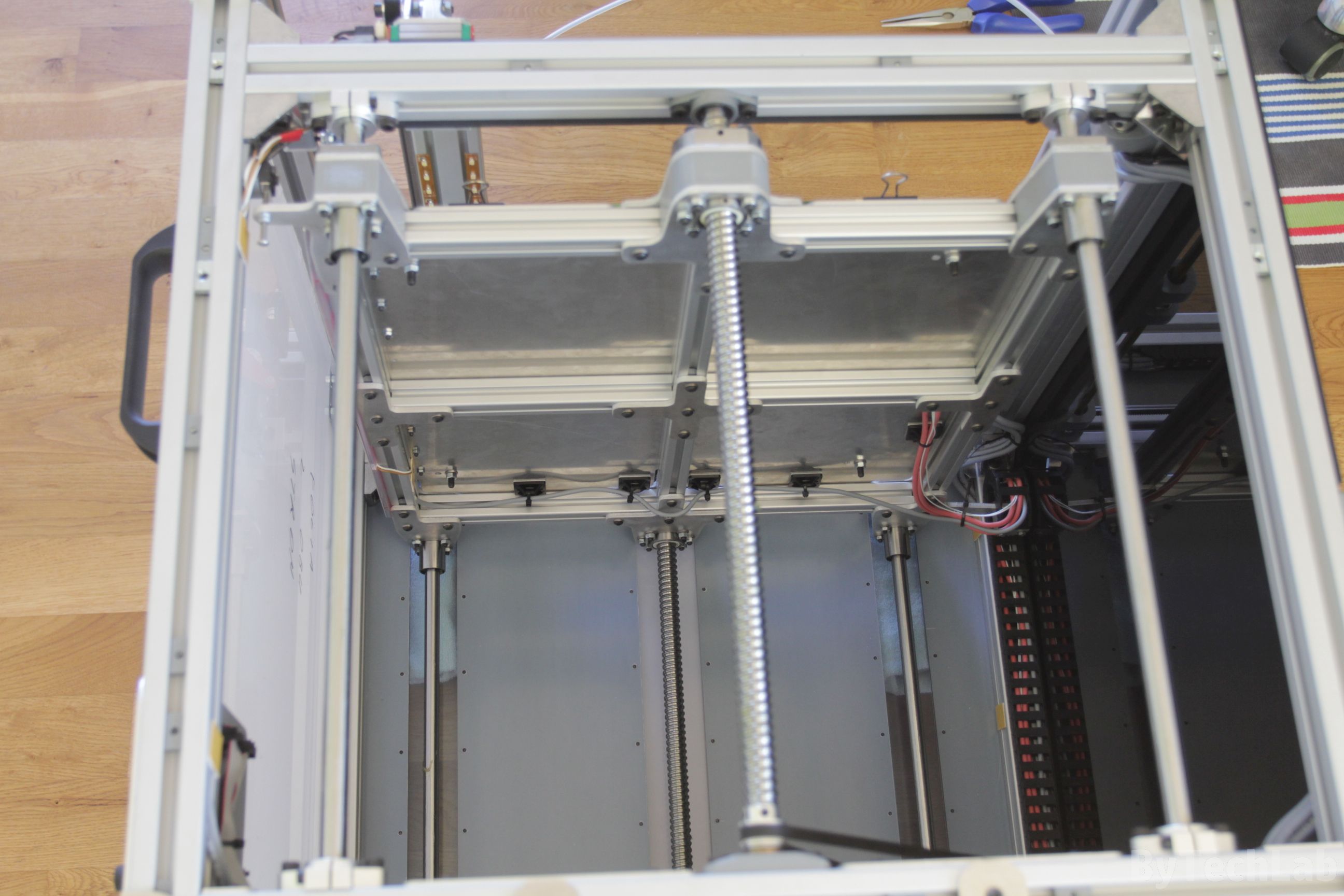
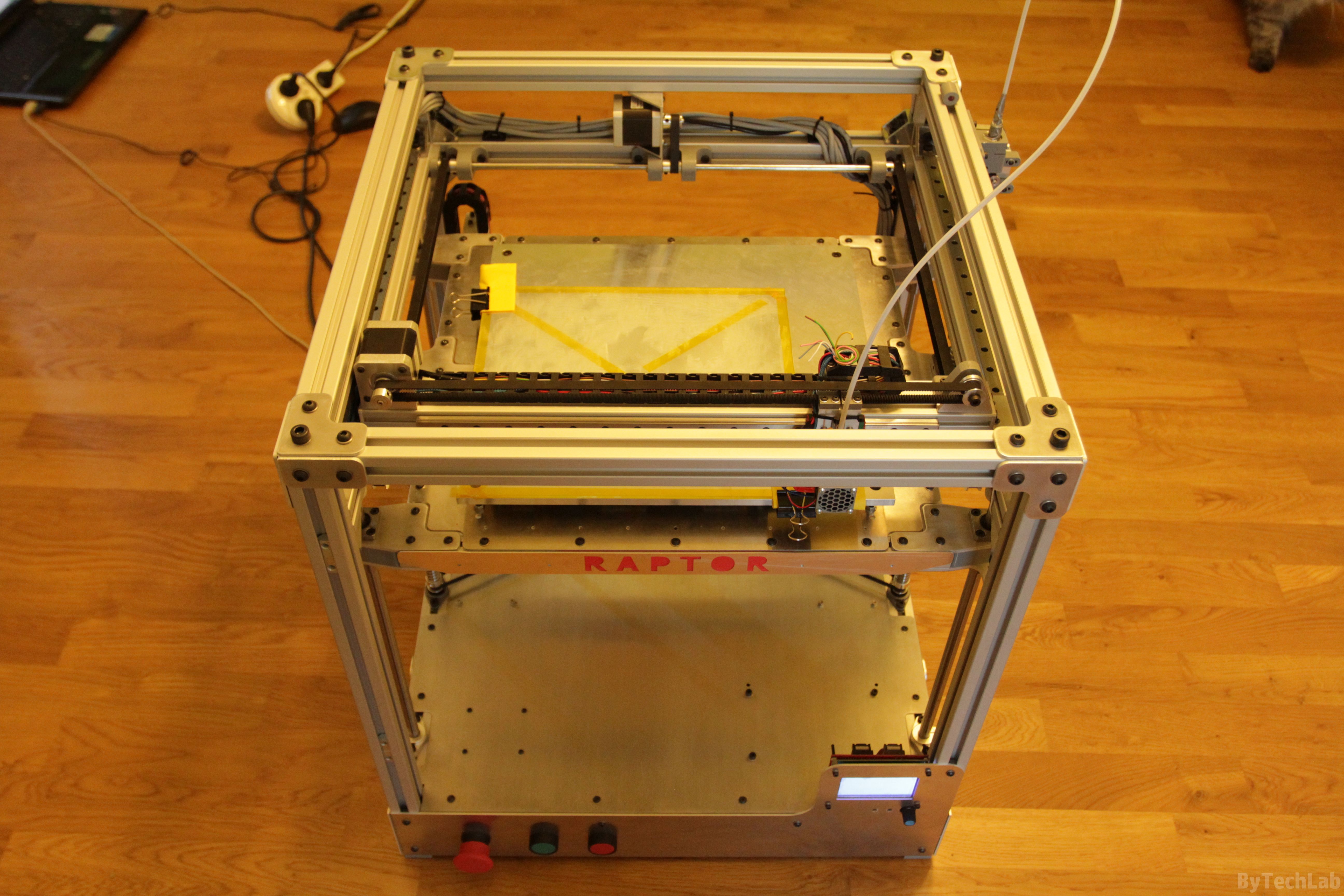
Z axis platform
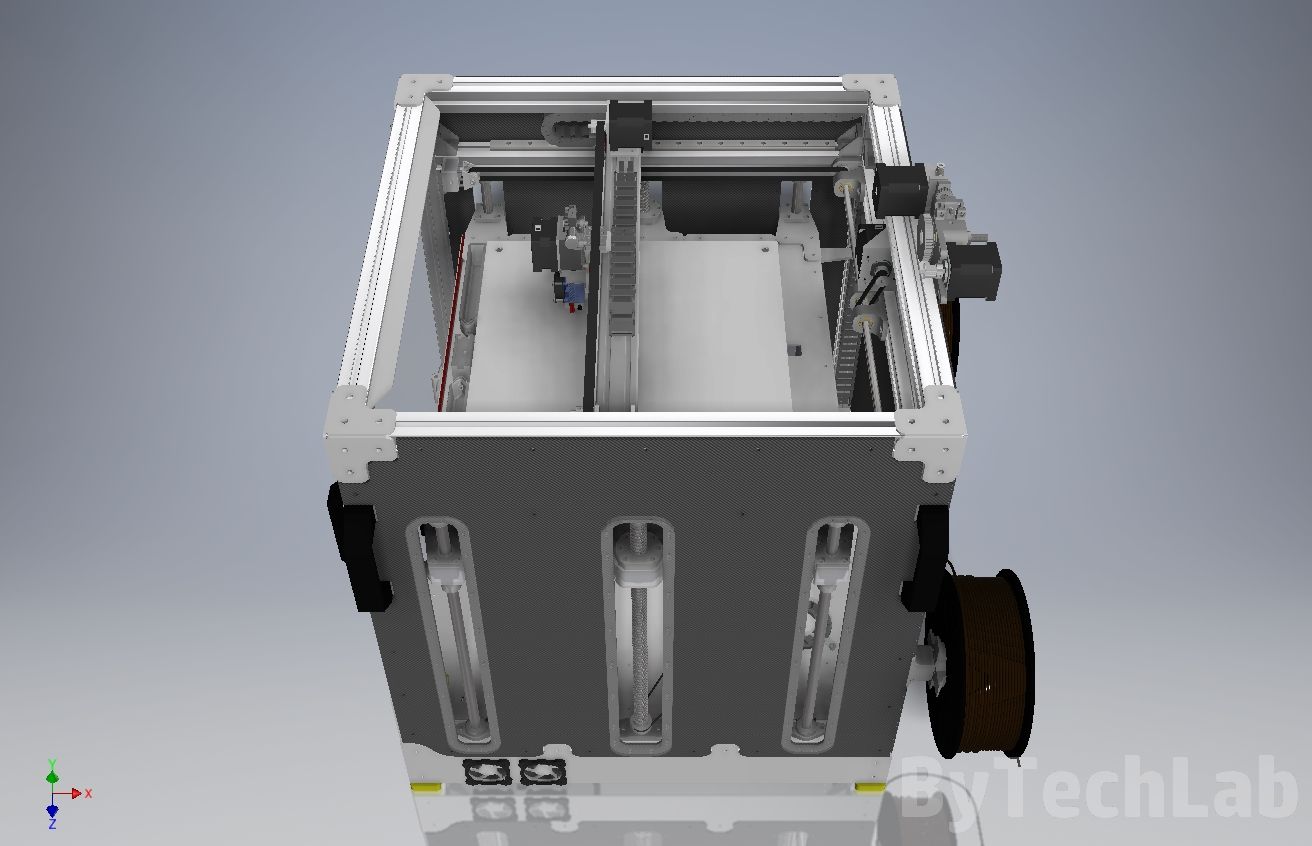
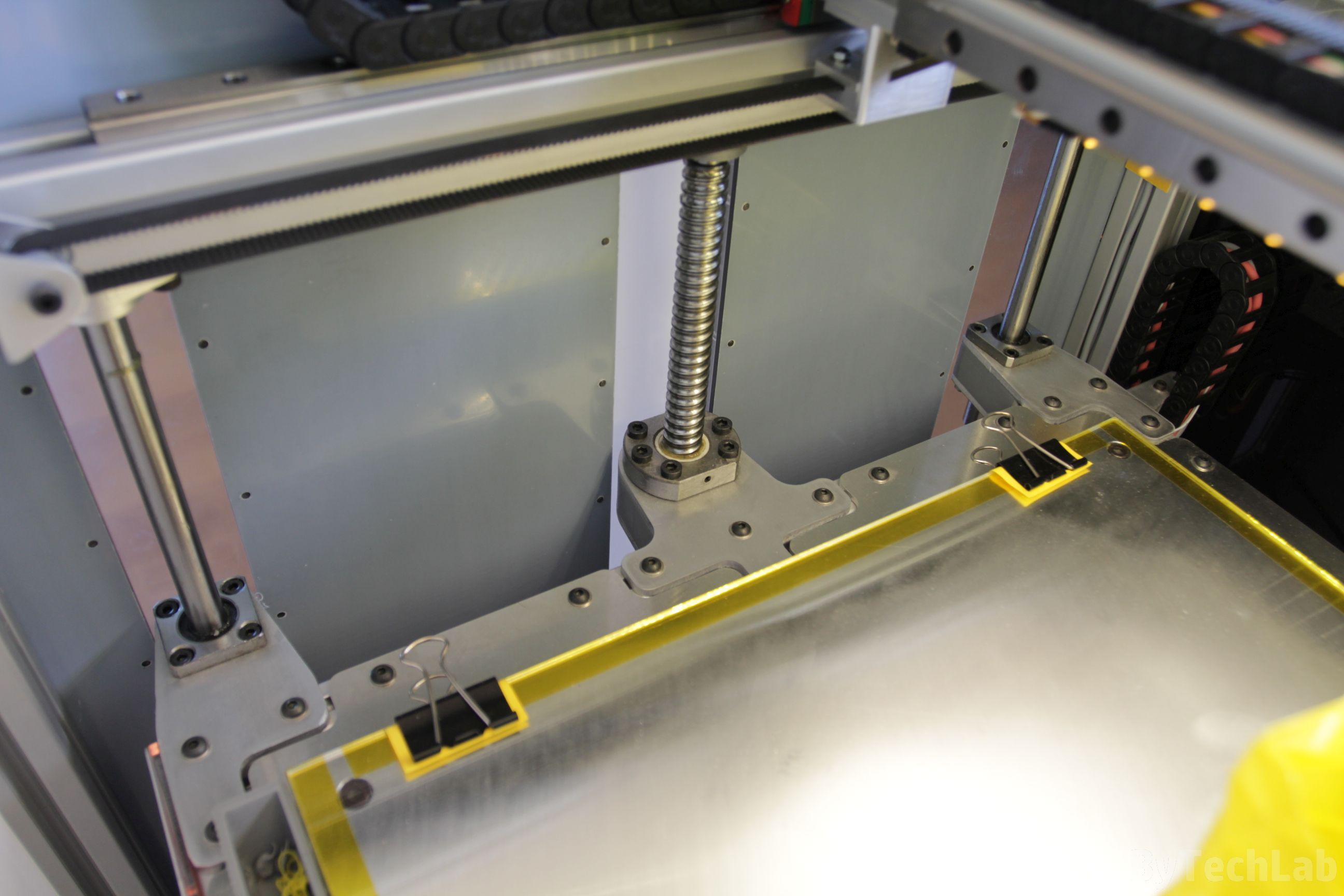
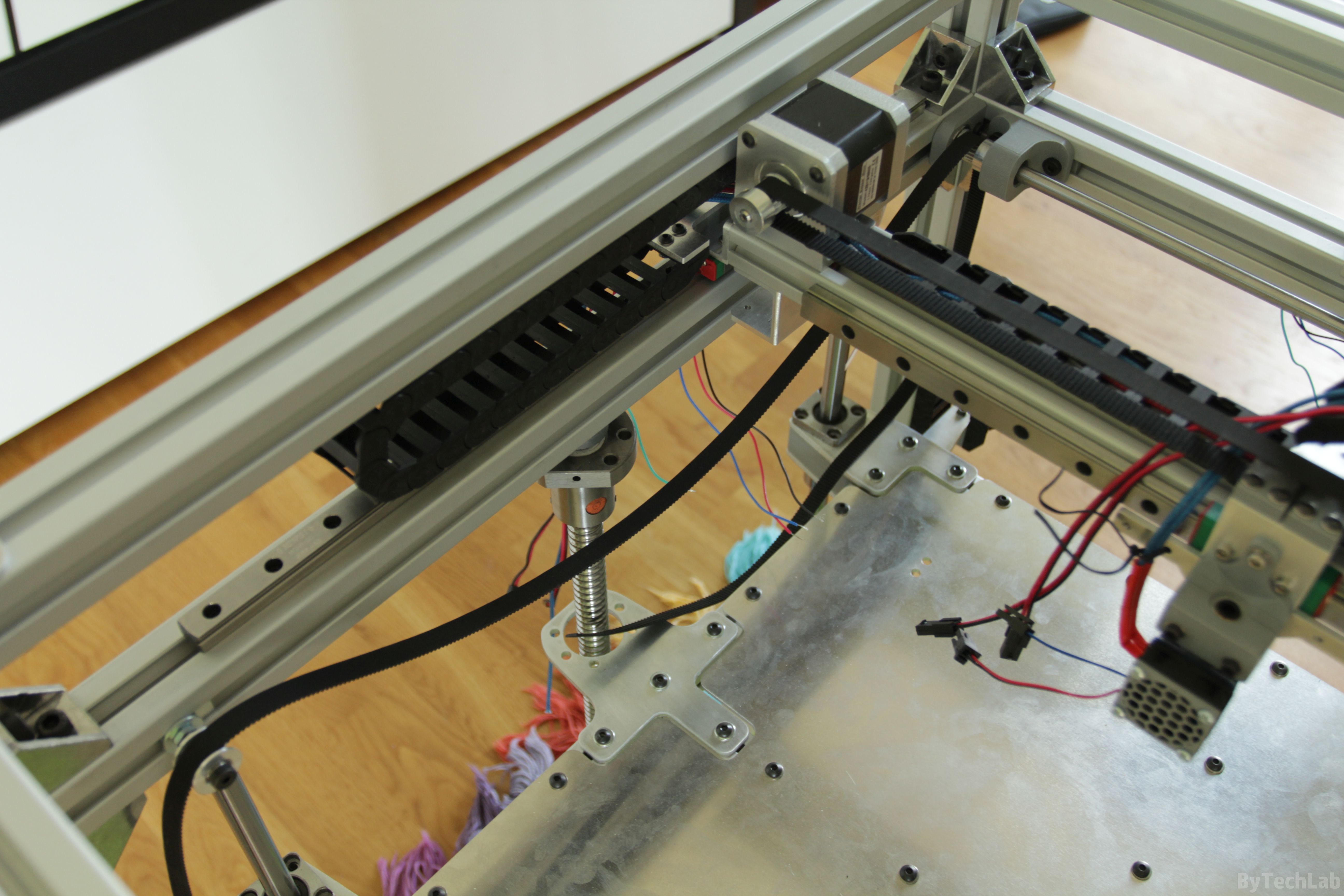
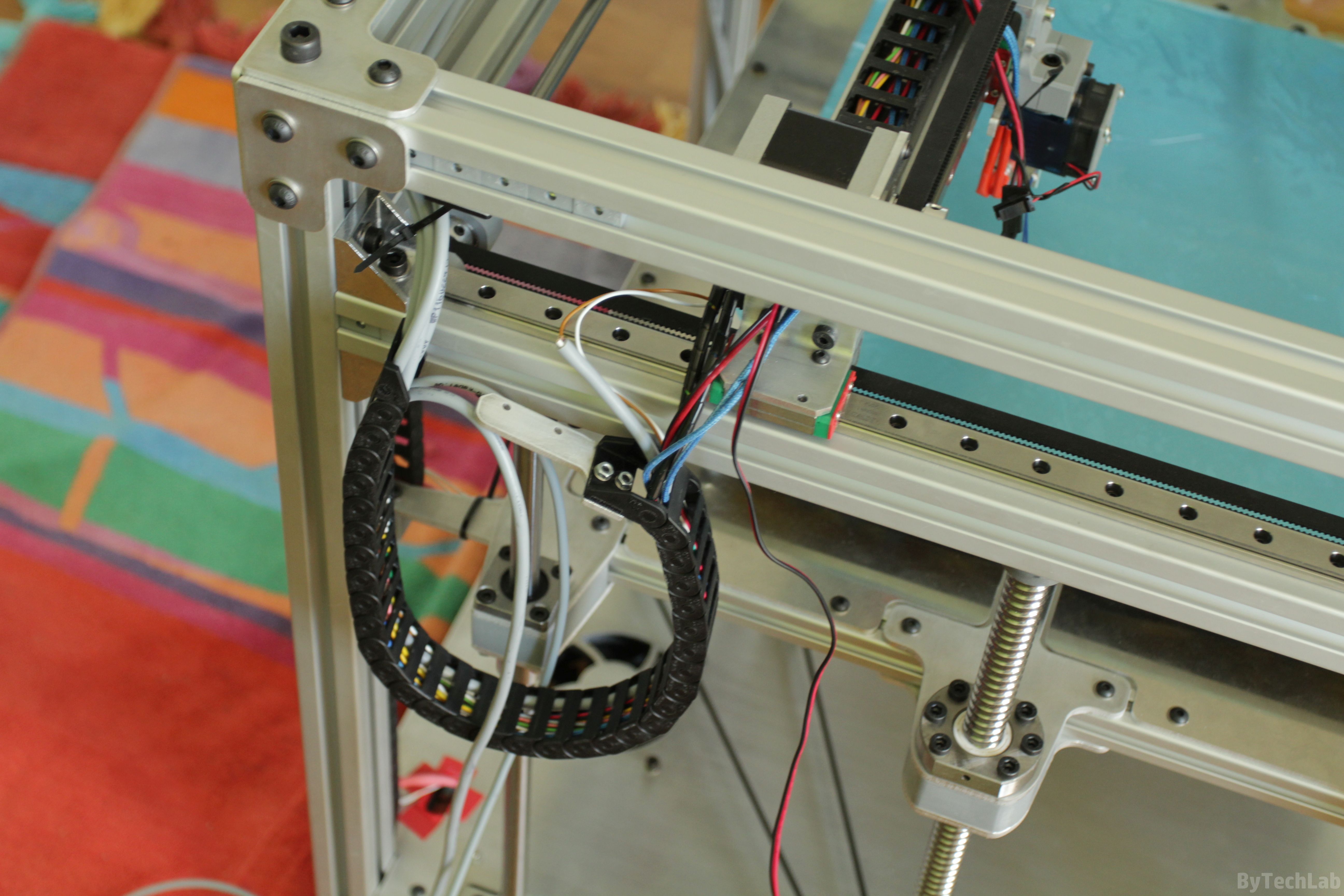
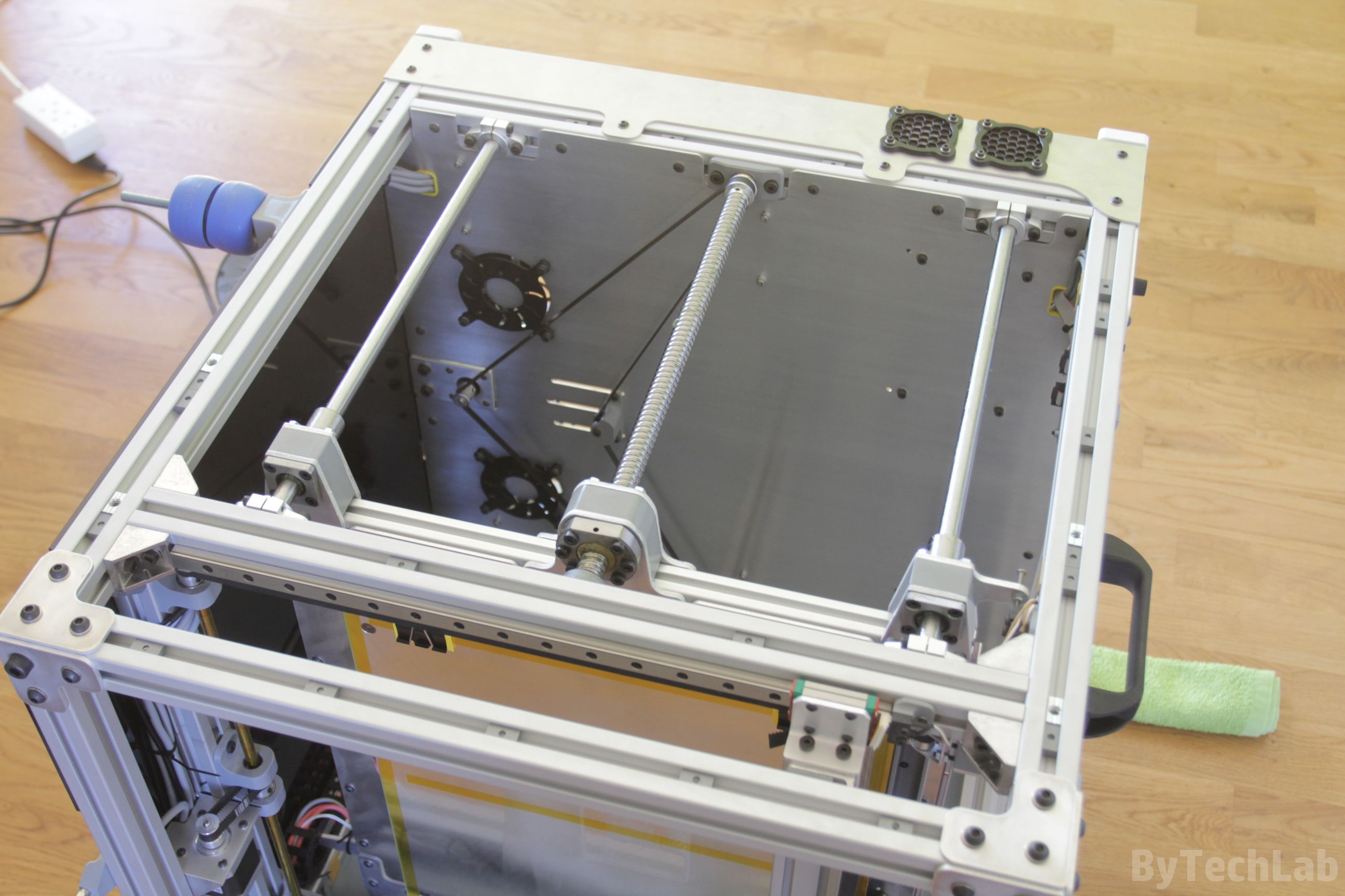
Because of size of this printer, the Z-axis platform is quite complicated. In order to achieve the maximum rigidity of the entire system, I used 2 1605 ball screws on both sides of the platform. On the corners of the Z axis platform I’ve installed LMK12LUU extended linear bearings that fit 12 diameter linear shafts. I didn’t wanted to use trapezoidal screws because they are bent very often and they would wear-out quite fast with such an load. Therefore, I used 1605 ball screws mounted on both sides. This is not the cheapest solution but it is definitely worth the price – I don’t have any problems with the Z axis now. The whole Z axis platform is almost bulletproof , it is 36 mm thick in some places 😎 .
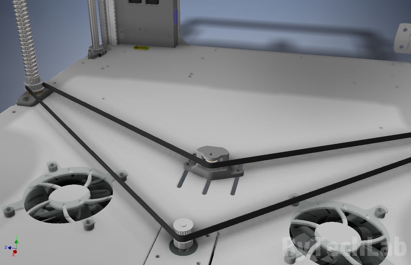
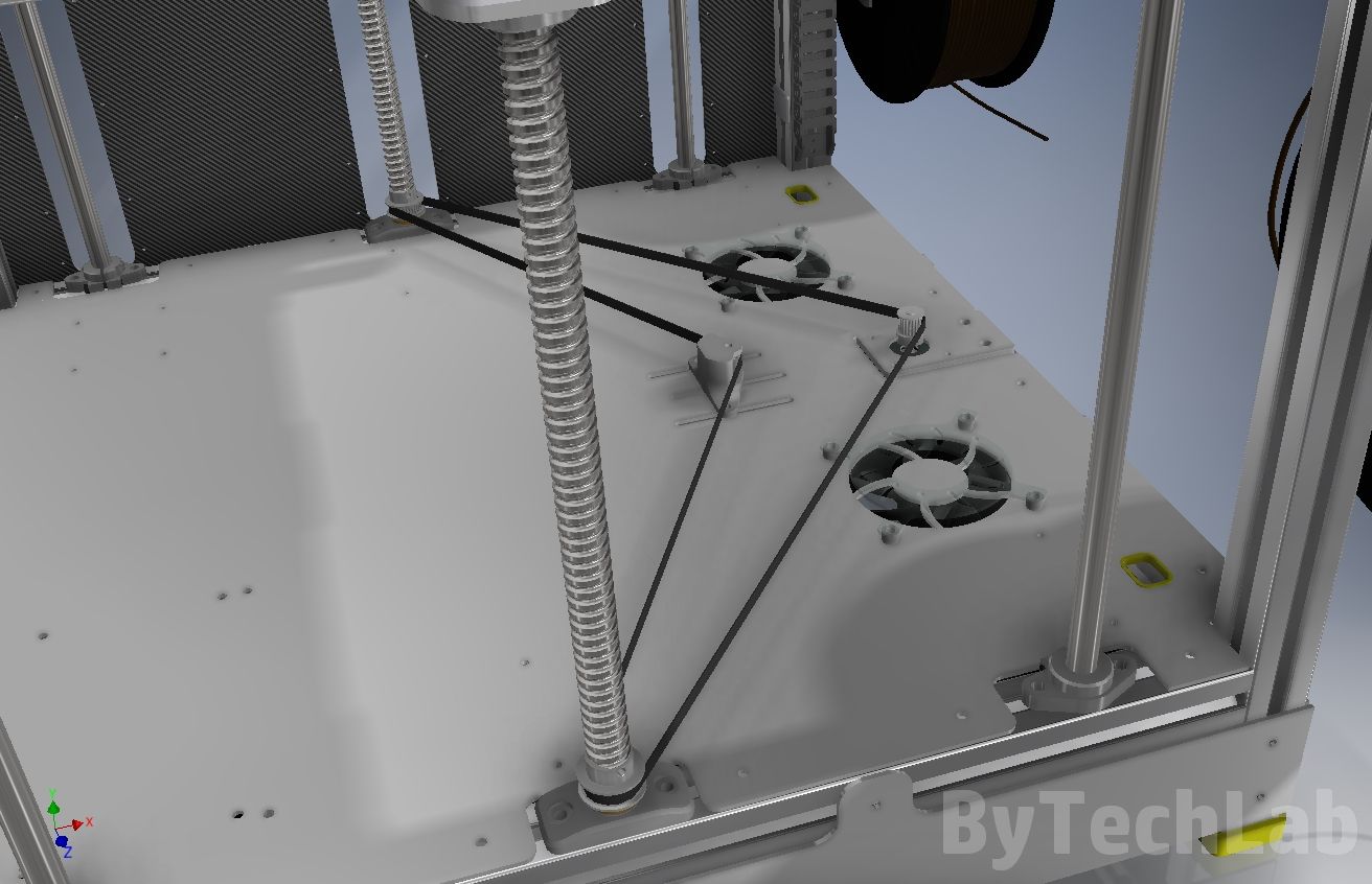
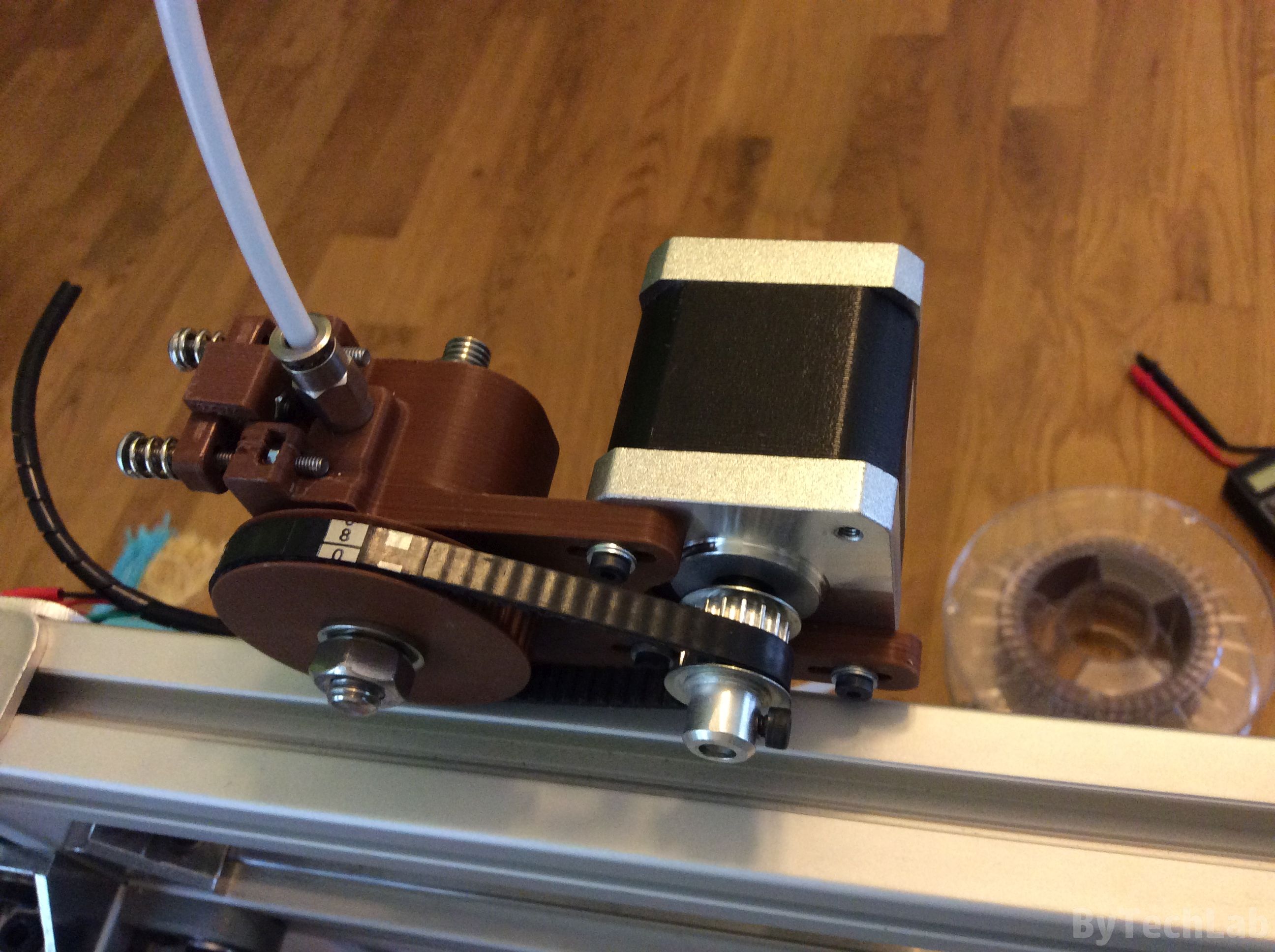
In addition, I have eliminated the problem of Z axis lead screw “de-synchronization” by using an closed-loop GT2 timing belt that links everything together nicely. When designing the printer, I had to adjust some dimensions of bottom aluminium plate to make sure that belt can be properly tensioned. I wrote a simple “script” in Inventor which uses some dimensions of the whole assembly and the belt itself (the distance between the screws and the motor, etc.). It allowed me to determine where the belt tensioning block will be located when the belt will be fully tensioned.
Z-axis ball screws have 40 teeth pulley’s on their turned ends , and a 20 teeth pulley is mounted on the Z axis stepper motor which is located in the middle of the bottom plate. Because of this there is an small “gearbox” (1: 2 gear raito) which allows me to obtain a higher torque on the ball screws that are quite hard to rotate( they support a very large weight). The “tensioning” block consists of standard flanged ball bearings with a bolt passing through them. The “tensioning” block is printed from ABS filament. The entire part is attached to the bottom plate with 3 bolts that pass through the slots that allow you to adjust the belt tension.
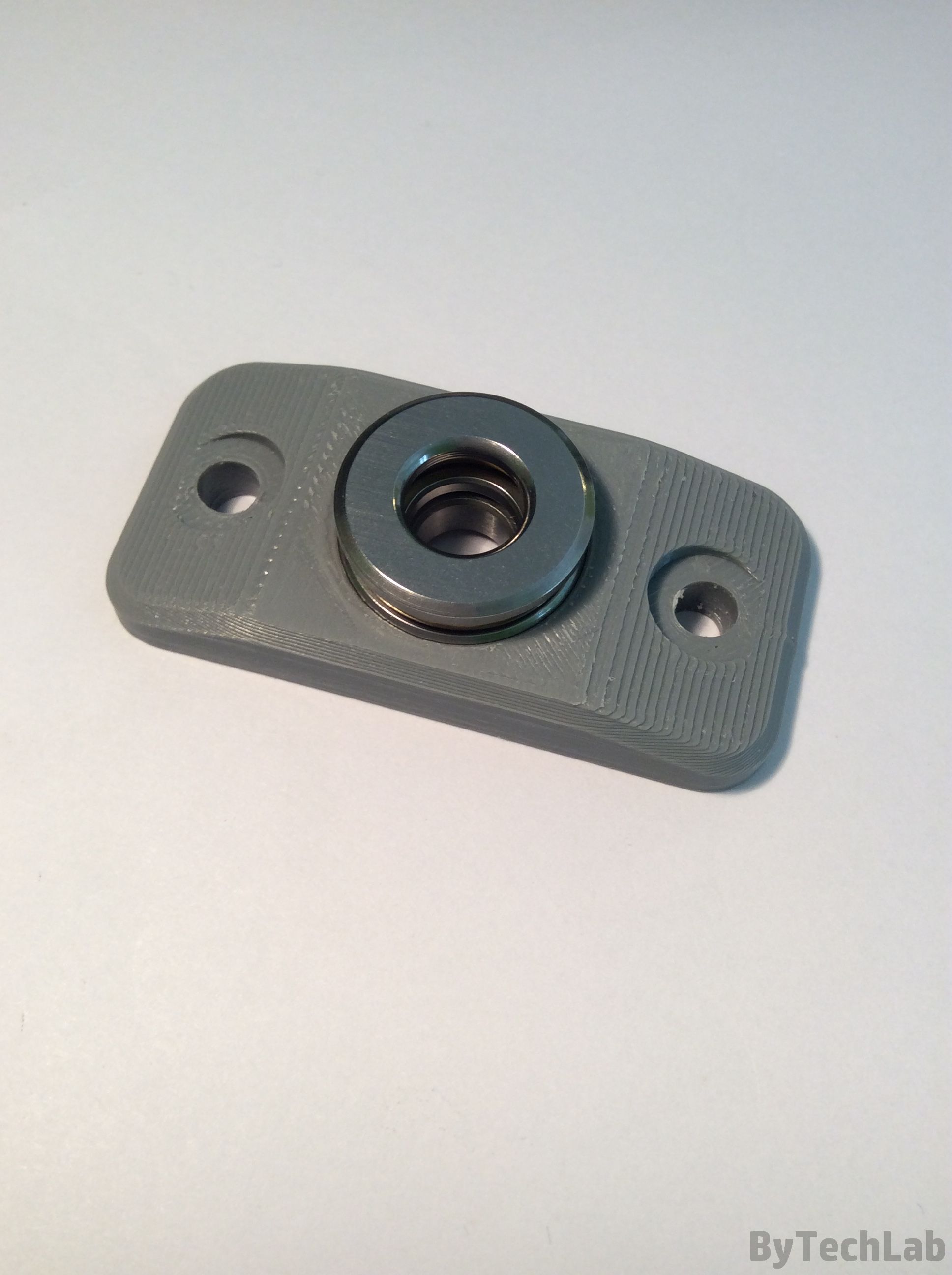

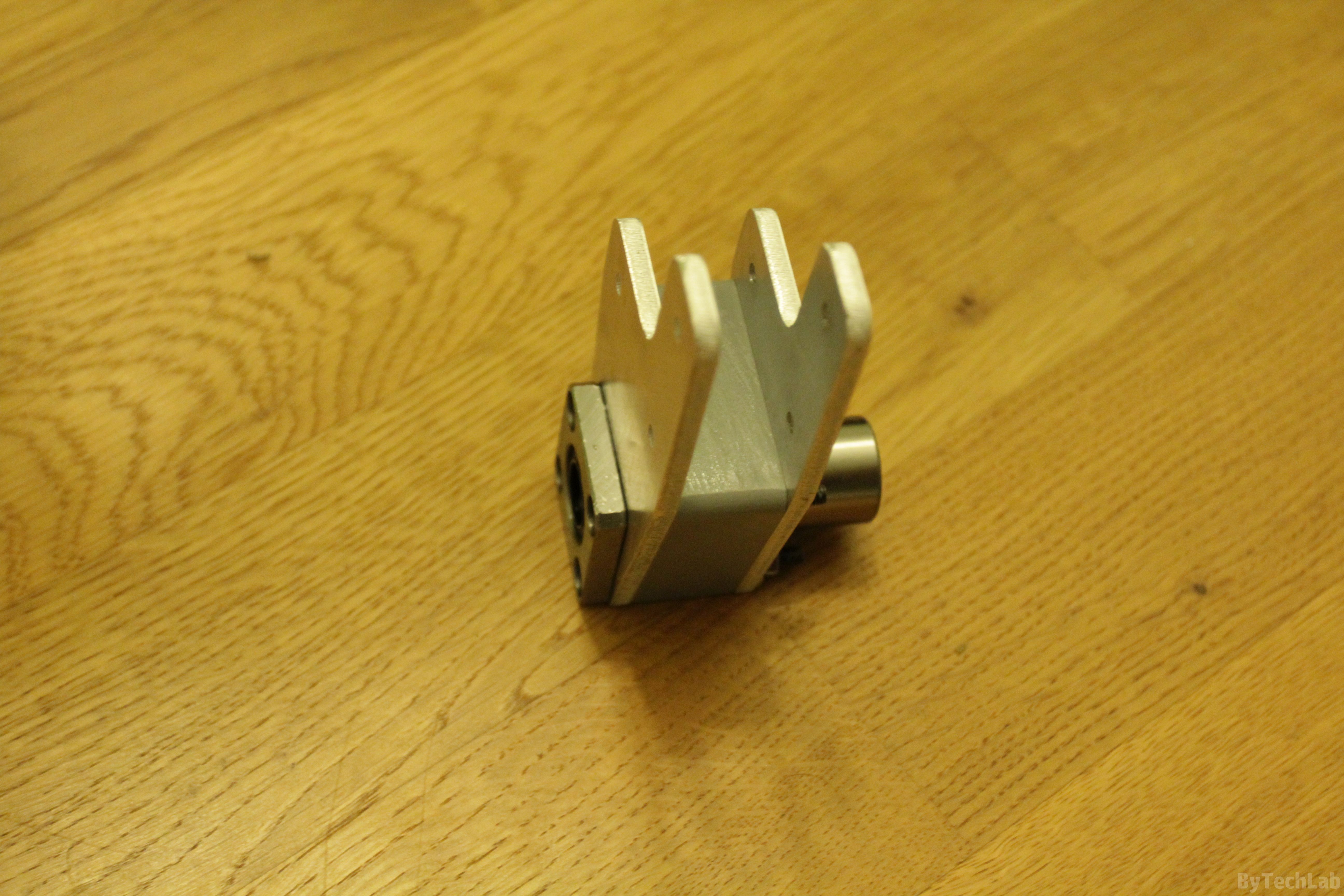
At the beginning, there were installed an ordinary ball bearings which supported ball screws .As it soon turned out, they couldn’t survive high axial load. As there was no space for a standard bearing block, I had to design my own which works just as well. It consists of a thrust bearing and an ordinary ball bearing. The thrust bearing transfers axial loads directly to the frame and the ball bearing prevents the ball screw from moving sideways. The block is printed from ABS, with 100% infill .I wanted to use an angular contact bearing, but I haven’t found anything that would fit into the available space.
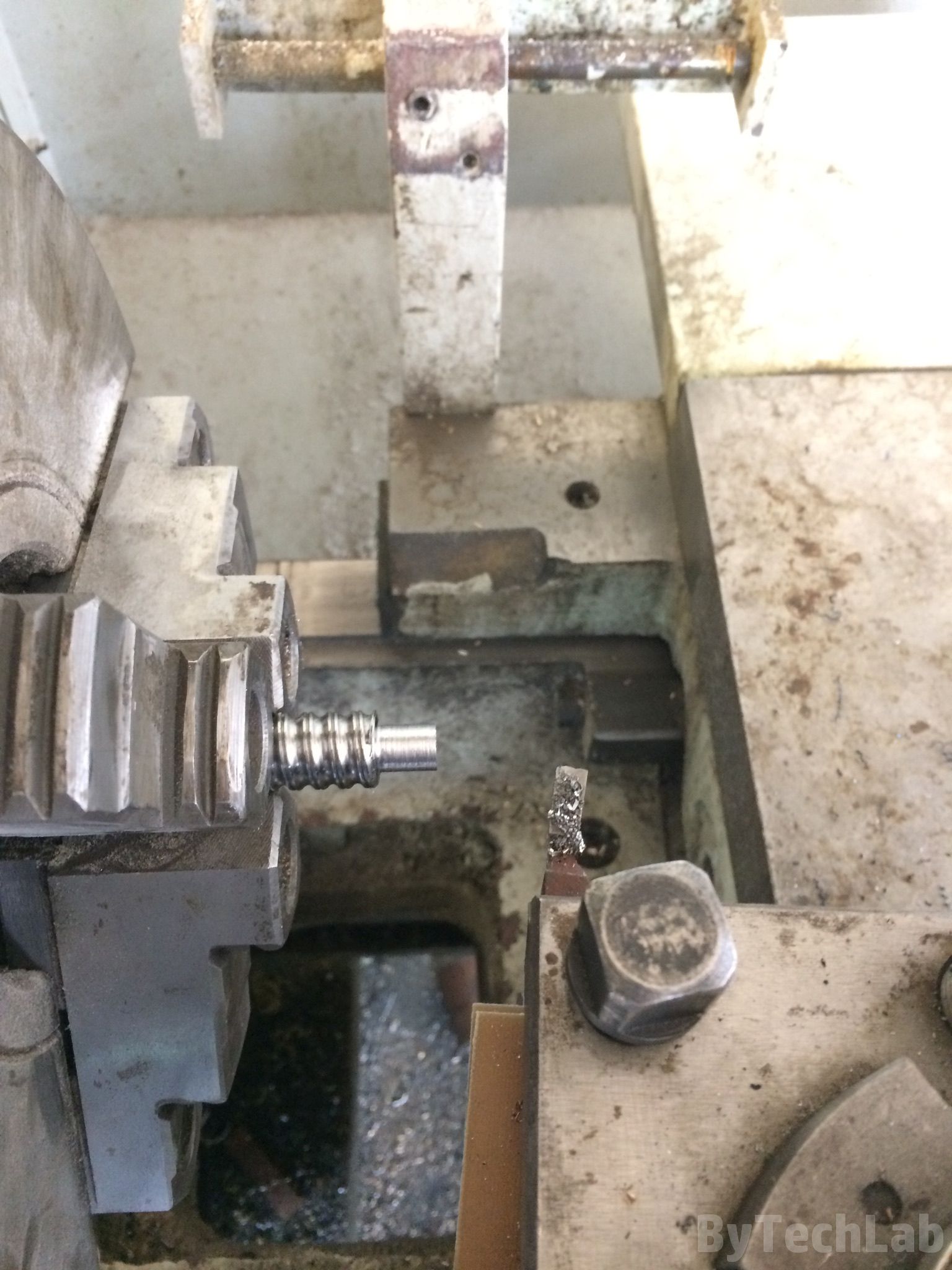
As the ball screws had ends that were too large in diameter, I had to turn them on the lathe to make them fit to the ball bearings. It wasn’t simple because it’s an surface hardened screw. At the beginning I had to machine the top layer with a carbide insert and then everything was going smoothly. I just needed to watch out for dimensions. At the beginning I tried to machine a very short piece of screw that is useless to make sure that everything will be ok with the longer ones. As you might have guessed, I have messed it up – the diameter was about 0.2 mm lower than required 🙄 . Because of that I had to be much more careful when machining the longer one’s.
I started assembling the Z-axis platform by attaching the 20 x 20 mm aluminium profiles to an 4 mm thick aluminium plate by using many bolts. In addition, from the bottom side of it I bolted down some aluminum brackets that make the entire platform more rigid. Everything was fitting together nicely. Holes in the main plate used to bolt down the heatbed were the only thing that I had to improve (I forgot to take the thermal expansion into account ).
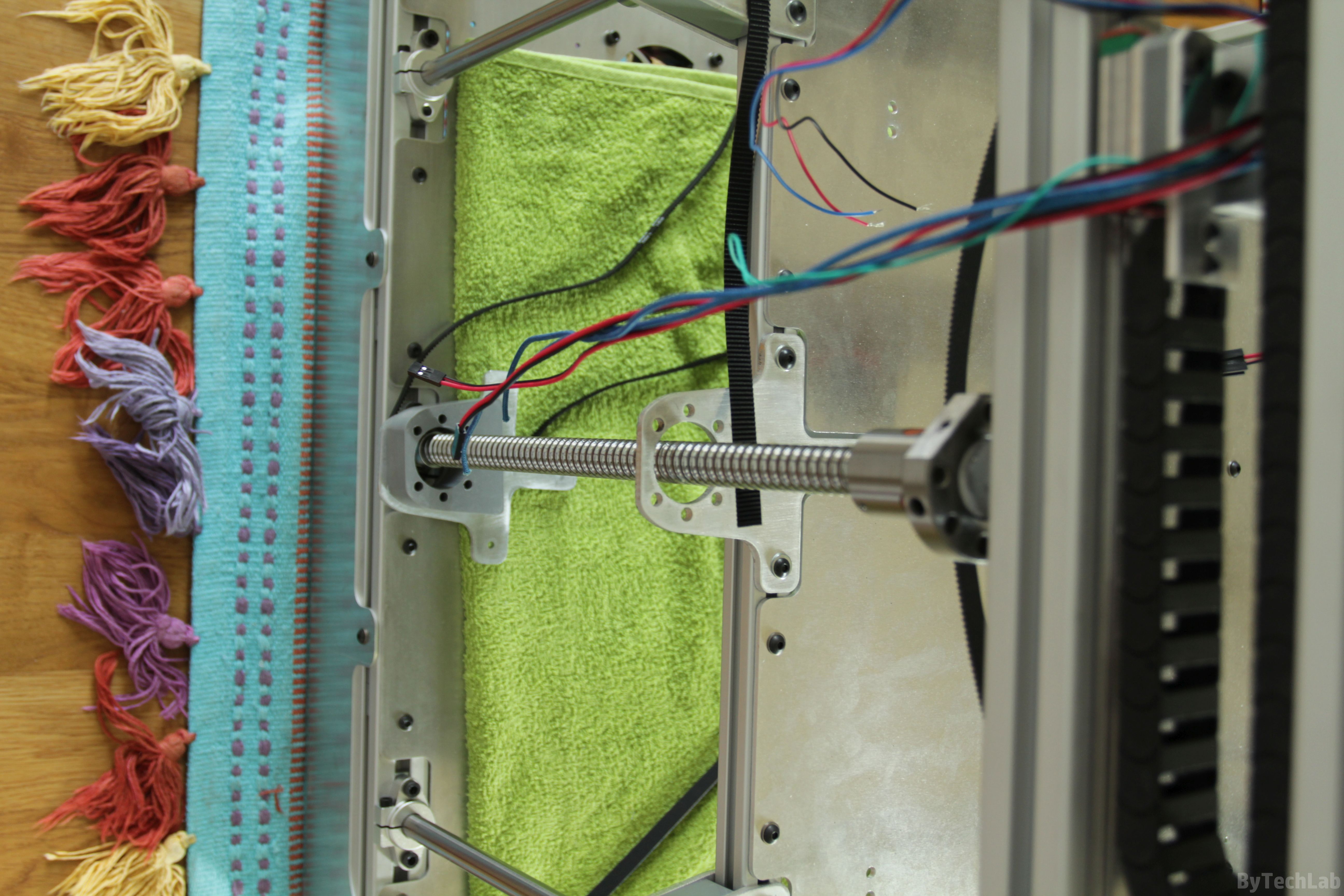
All linear bearings and ball nuts are attached to the platform with an mounting brackets that look like an sandwich.These mounting brackets are made of 3 parts: 4 mm thick aluminum sheet on top and bottom with an solid 3D printed ABS fillers between them. Because of this, it is possible to significantly increase the rigidity of the whole Z-axis assembly. Unfortunately, it wasn’t possible to design it in the way that the linear shafts and bearing blocks wouldn’t stick out from the frame contour. It is only a millimeter or two, but because of this it was impossible to attach the side Plexiglas panels to the frame. I solved this problem in a quite interesting and visually attractive way about which I will write later in this article.
The whole Z-axis platform is very rigid. There is no chance to bend it by pressing your hand on the edge of it. Due to its mass and inertia, it doesn’t vibrate at all .Vibrations on the z-axis platform could potentially cause numerous defects on the 3D prints. Accuracy and repeatability of movement of the whole system is very surprising – I have made multiple tests with an dial indicator. Ball screws driven by a single belt are excellent – I will never use two or more stepper motors in this axis.
X and Y axis
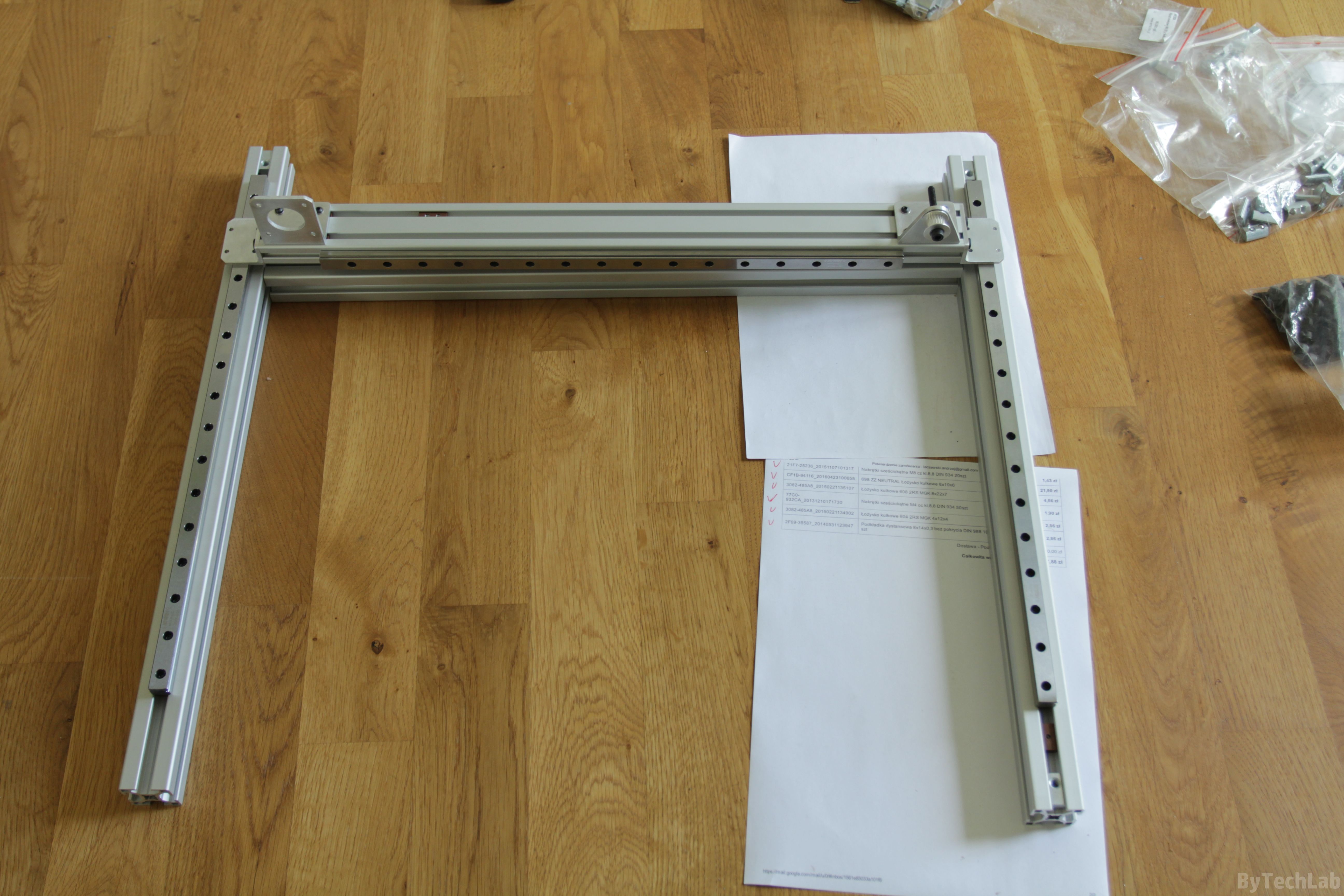
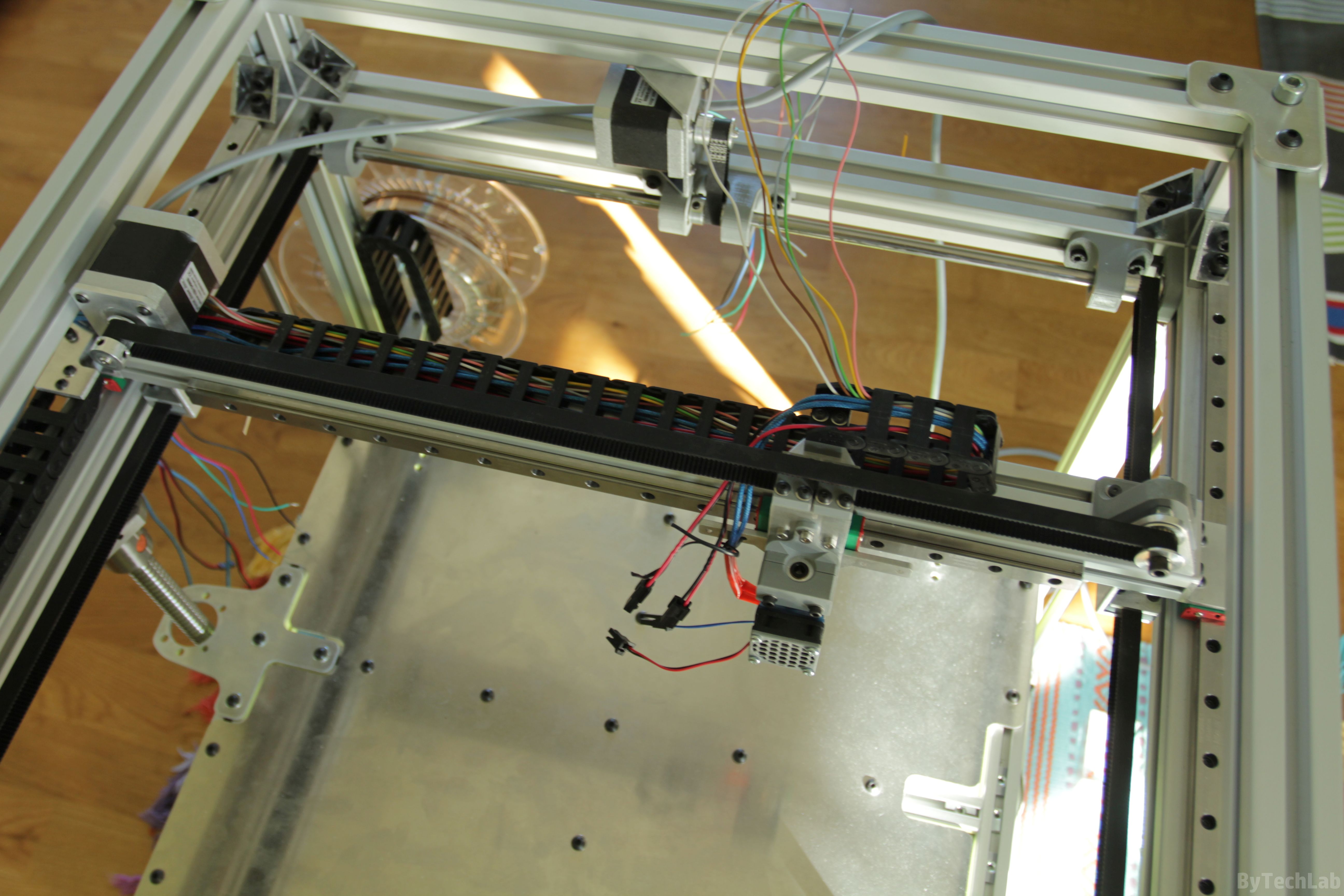
While designing, I decided to implement a simple cartesian-type kinematics with bullet proof mechanical design. In both axes, I used the genuine HIWIN MGNR12 linear rails and HIWIN MGN12H bearing blocks. All linear rails are bolted down with short M3 bolts directly to metal T-slot nuts. I used some gauge blocks to align linear rails and make sure that they are perfectly pararell. The alignment of the whole X/Y kinematics took some time – I wanted to be sure of all dimensions, so that later there wouldn’t be any problems with jamming of the bearing blocks.
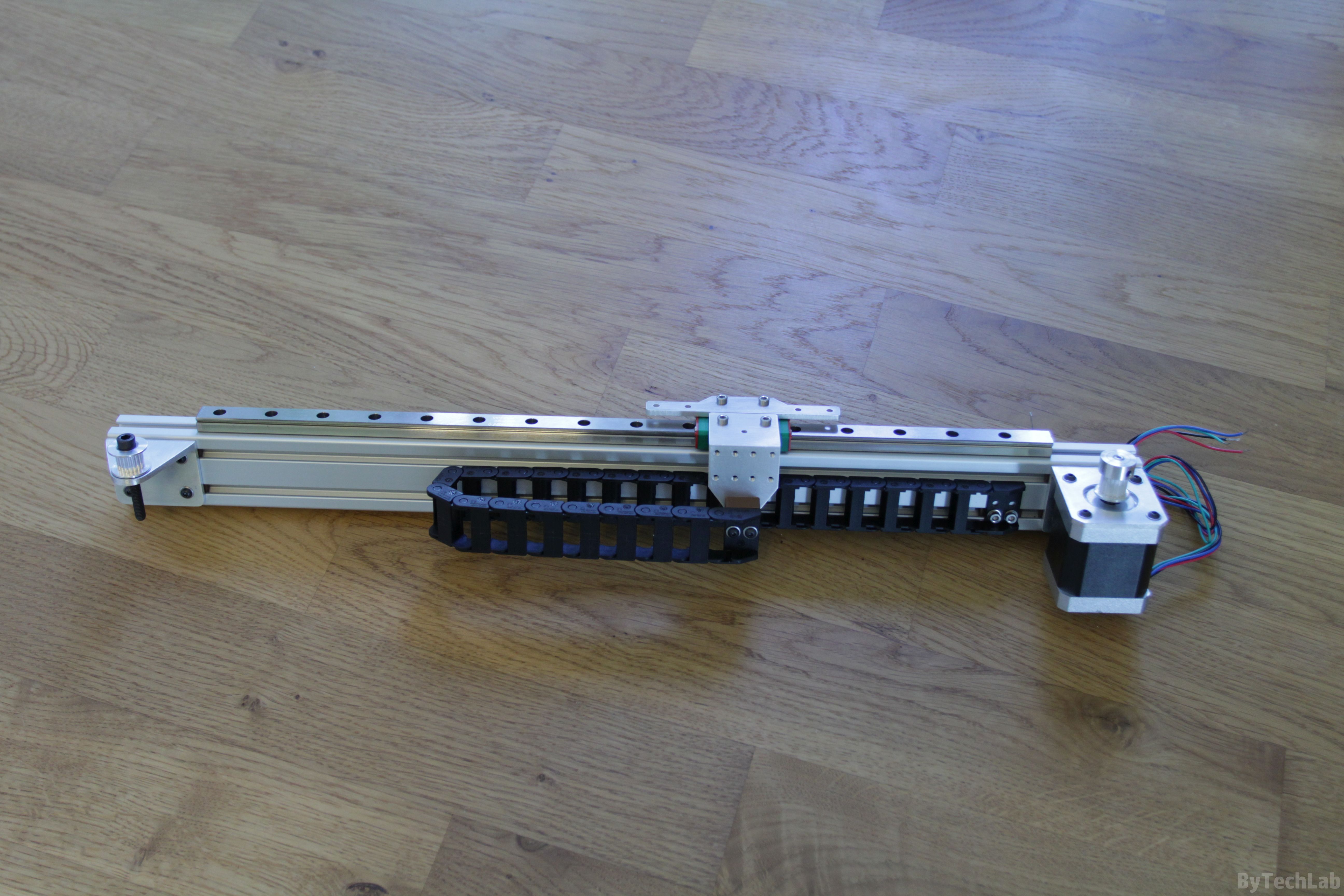
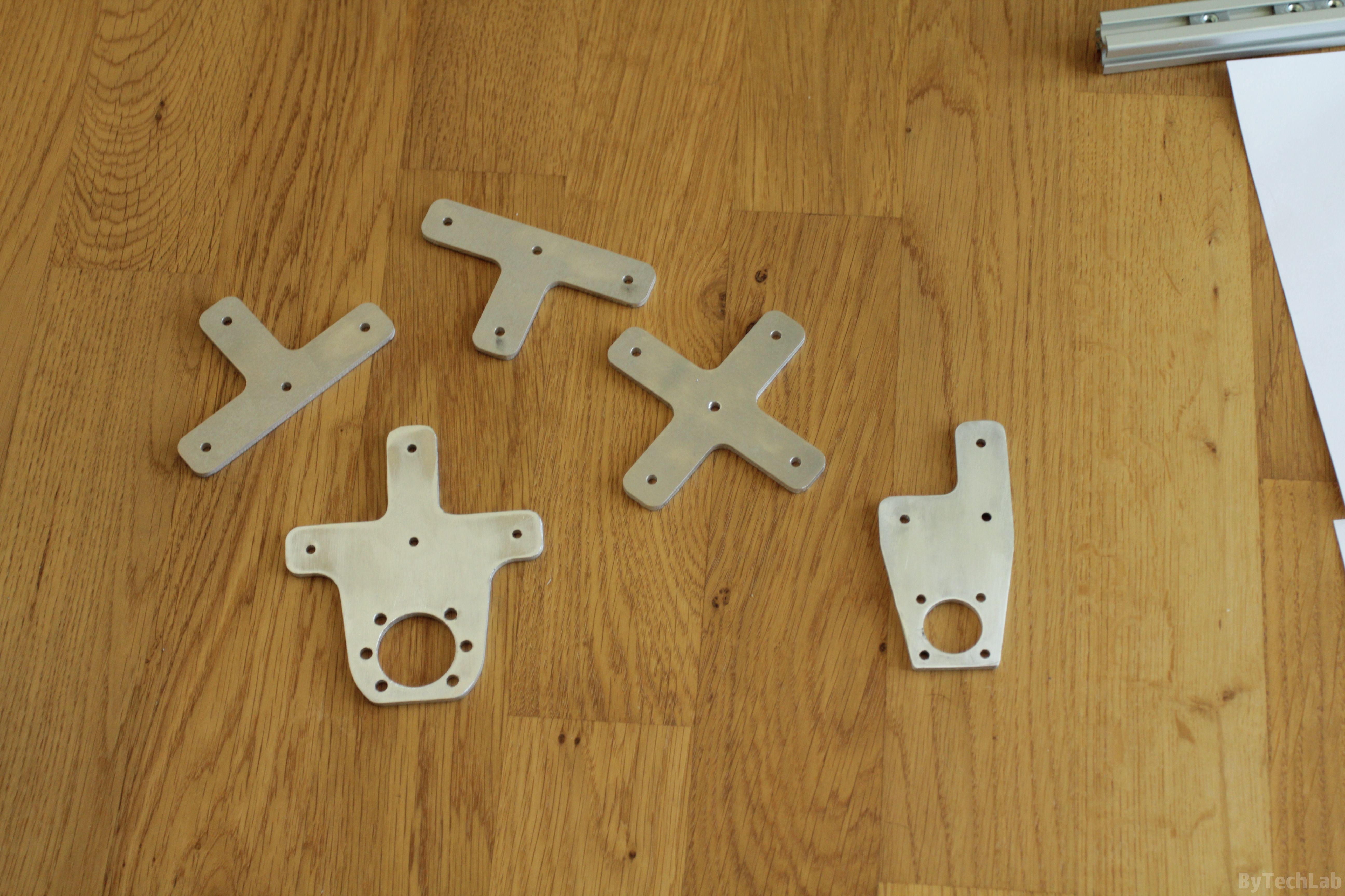
The entire X axis is based on the 20×40 aluminium extrusion profile. Stepper motor and belt idler mounting brackets were cut from an aluminum angle on a CNC milling machine. The end of the cable carrier from Igus has been attached to the X-axis carriage to improve overall appearance and to get rid of an “cable spaghetti” .In addition, I have attached aluminum plate with holes for additional accessories to the x-axis carriage .
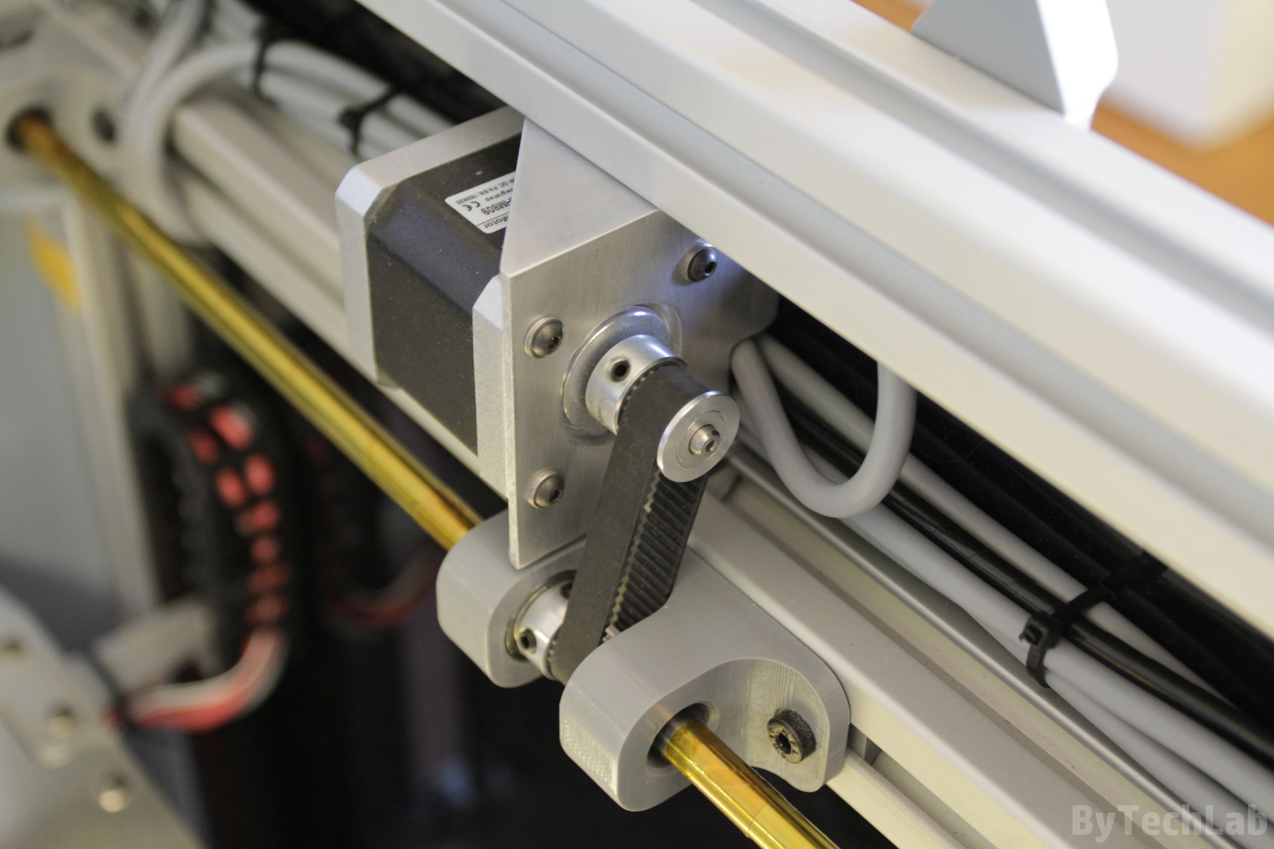

The Y-axis stepper motor is also attached to a aluminum profile that has been machined on CNC. Of course, all the mounting holes are in “slot shape” so that the belt can be easily tensioned. The drive from the stepper motor is transmitted through a closed loop timing belt to a steel shaft that has 8 mm diameter. The shaft drives both sides of the X axis evenly from both ends so that there are no problems with uneven distribution of forces. The shaft is attached to the frame with 3 bearing blocks.There are two ball bearings inside each one.
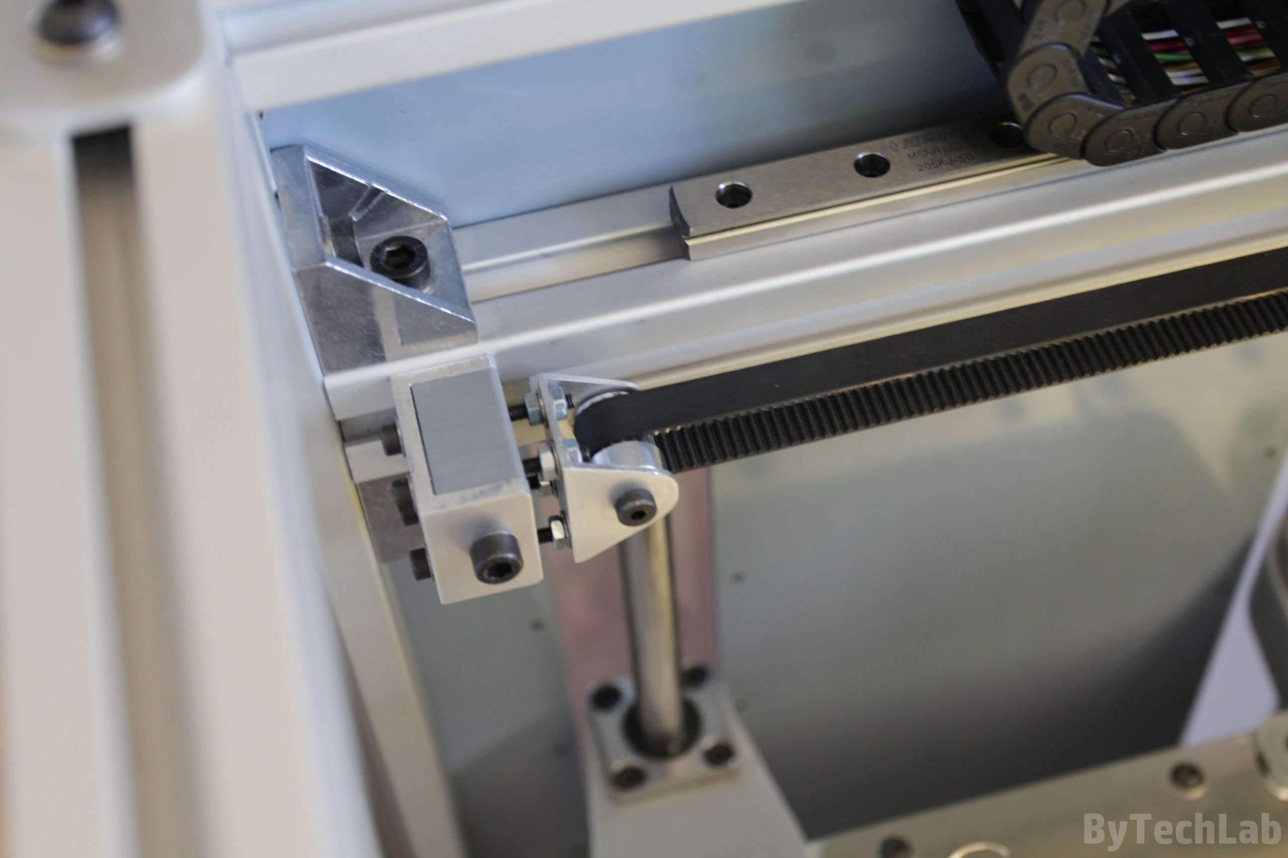
All timing belts are 9 mm wide (GT2 type). The Y-axis belts go through the pulley’s on the drive shaft and the idler on the other side. The tensioning mechanism was made of c-section aluminum profile and GT2 pulley’s with 4 small bearings inside. The belt is attached to the Y axis with an c-section aluminum profile (3 mm thick) .Belt is attached to this aluminium profile with two 3D printed clamps that firmly hold it in place from both sides.
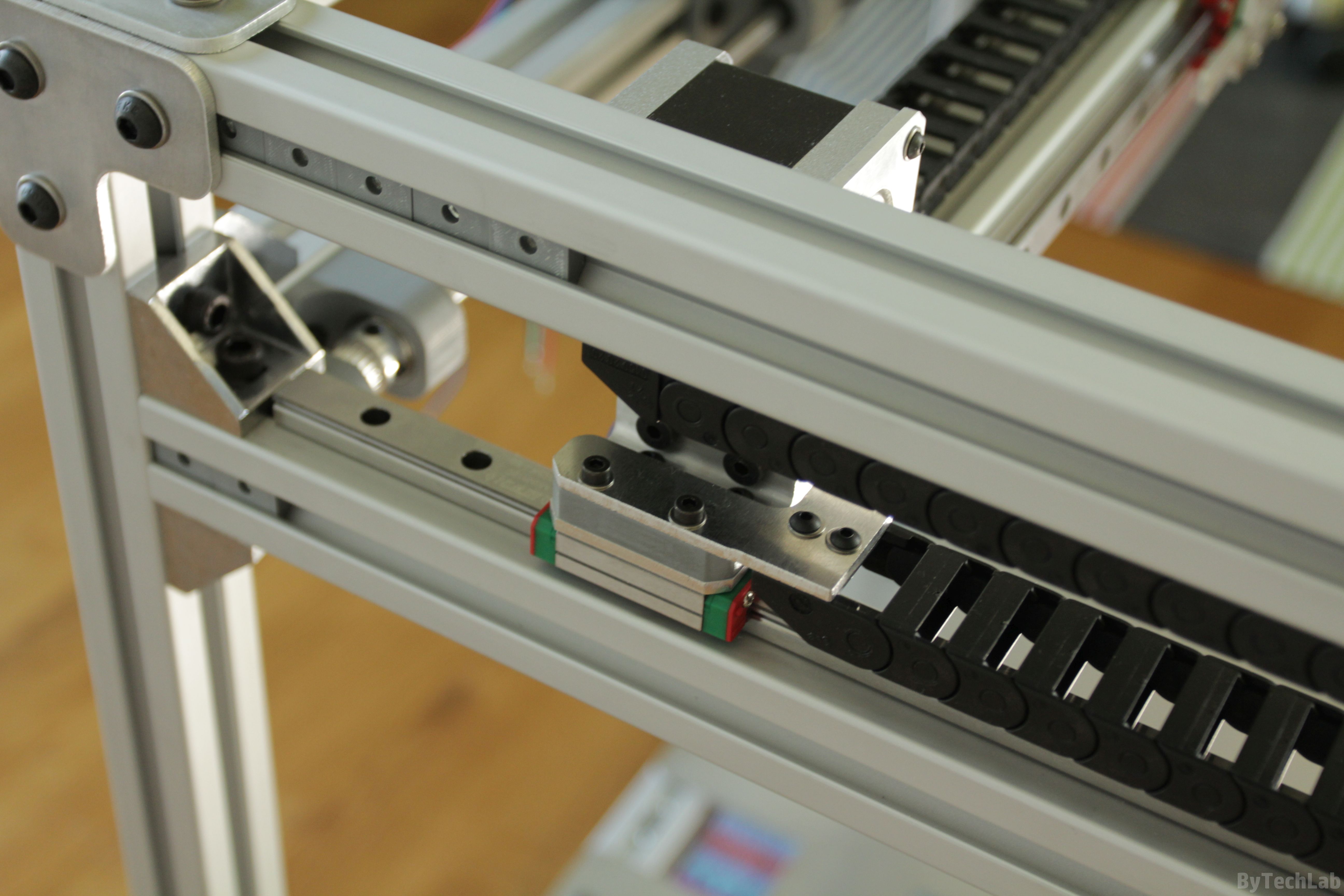
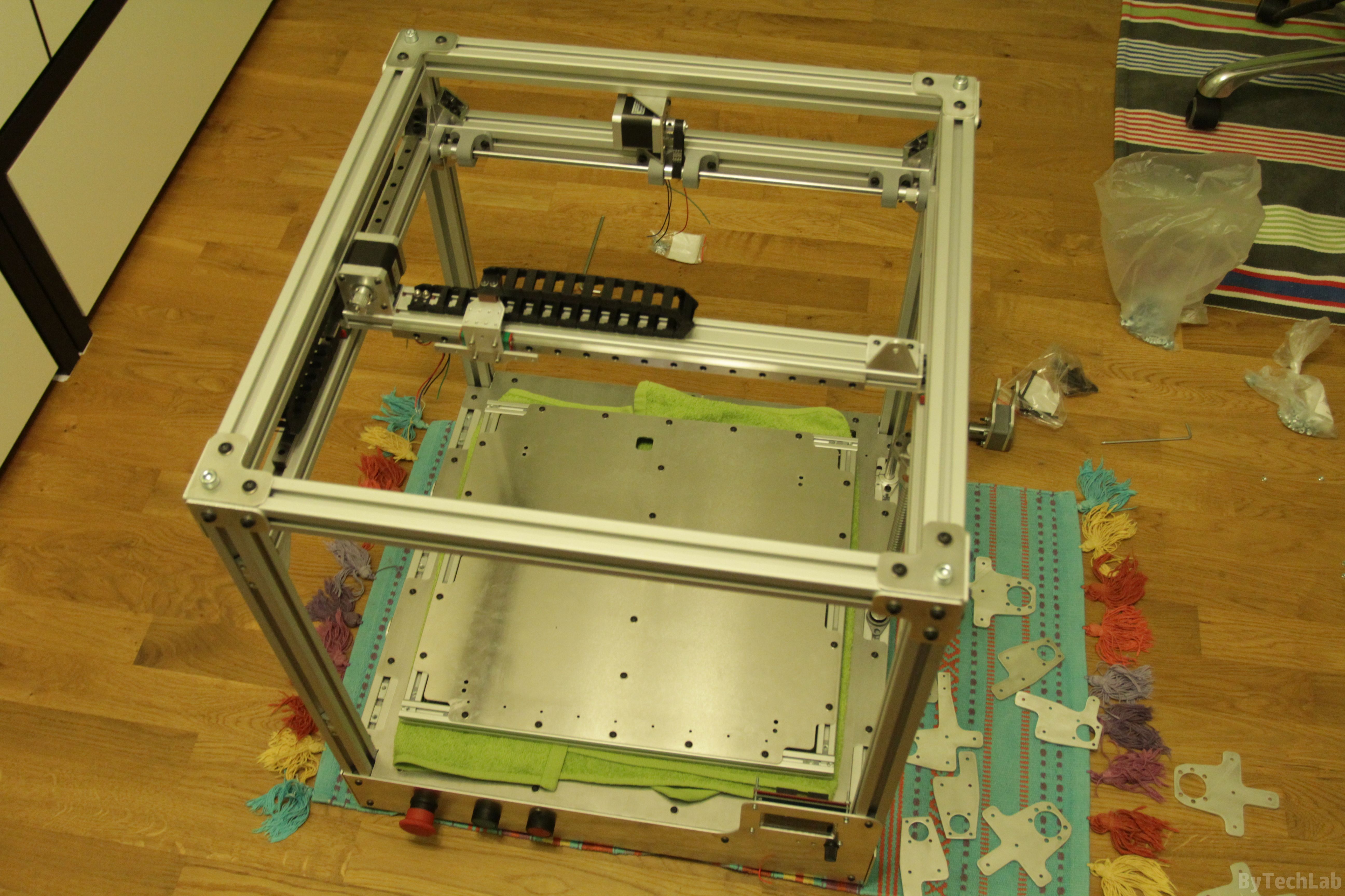
In the Y-axis, I have also used Igus cable carrier, it allows me to hide all wires nicely. All necessary parts have also been cut out of aluminum sheet. The X-axis beam has been attached to the Y-axis carriages with CNC milled aluminium angles. They are attached to the aluminium extrusion profile with bolts which enter the threaded “central” holes inside it. In the picture below you can see how the whole thing looks after X/Y kinematics assembly is finished:
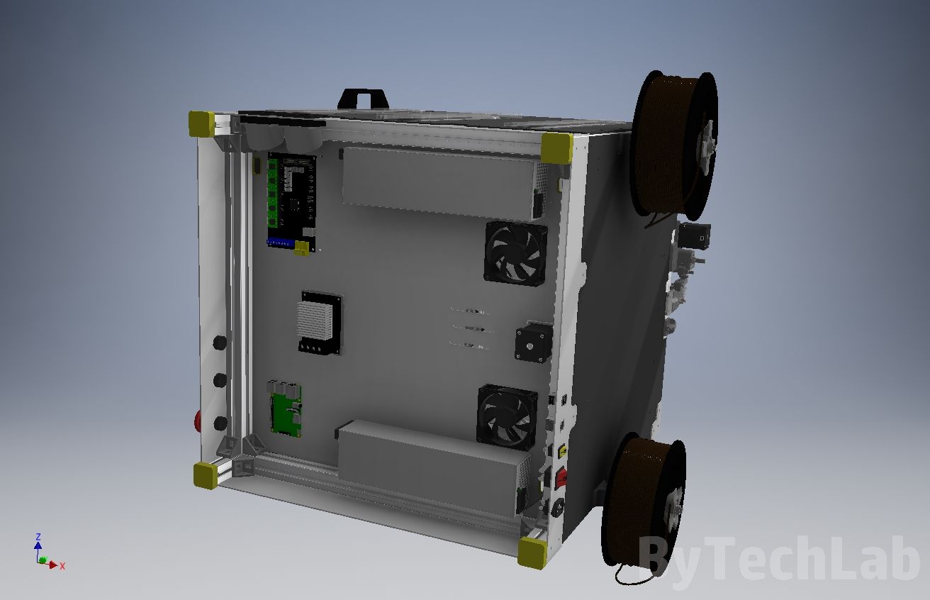
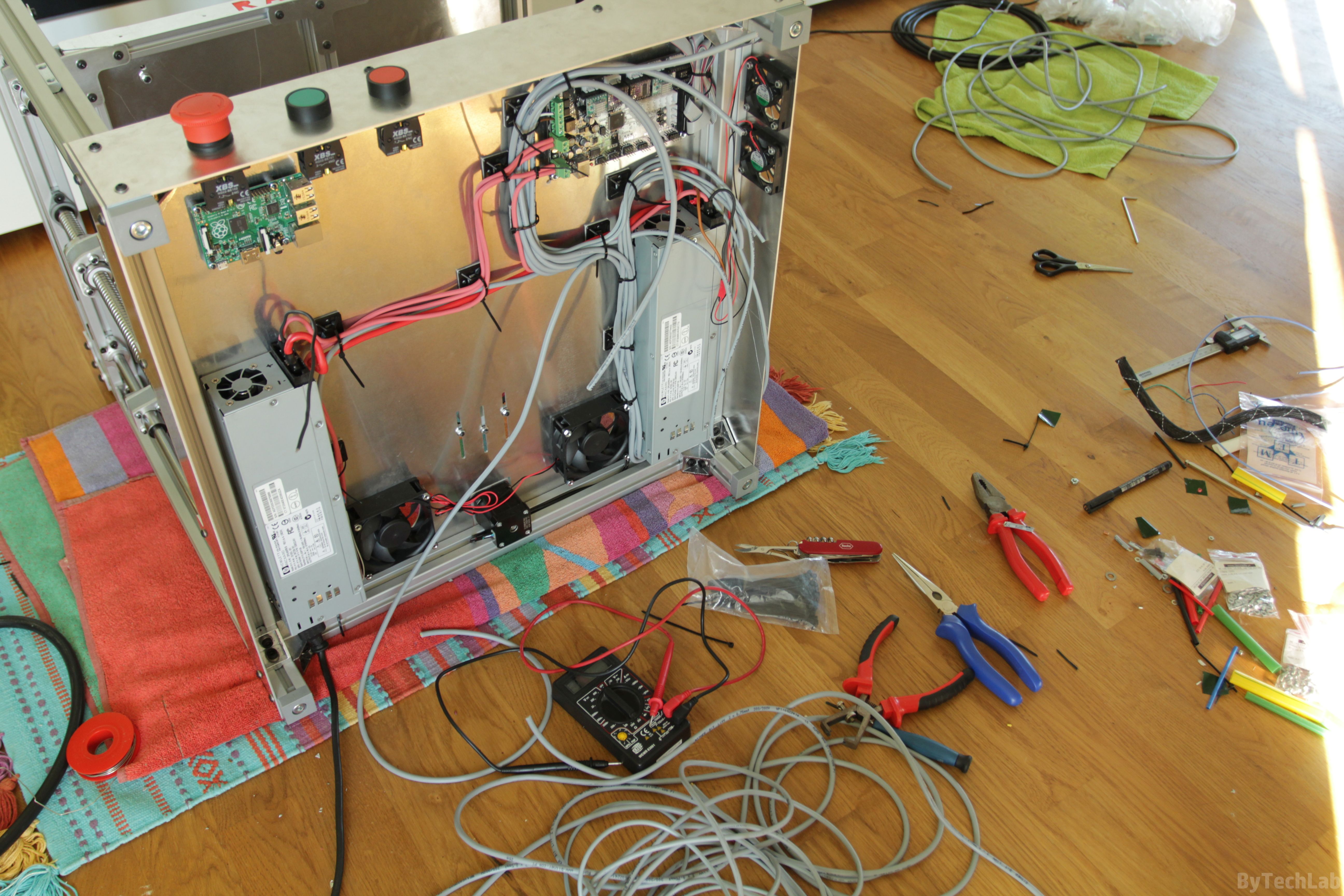
Electronics
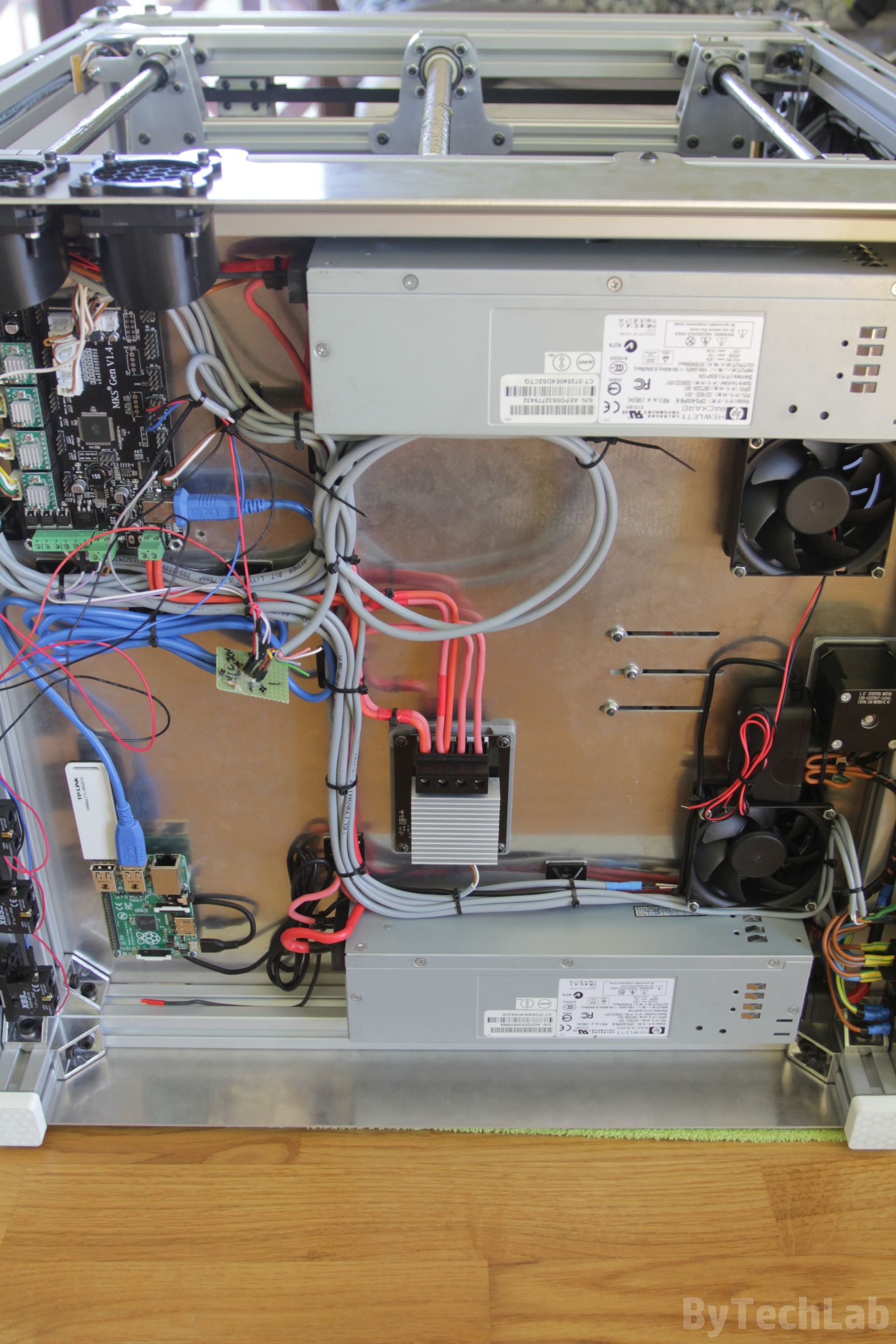
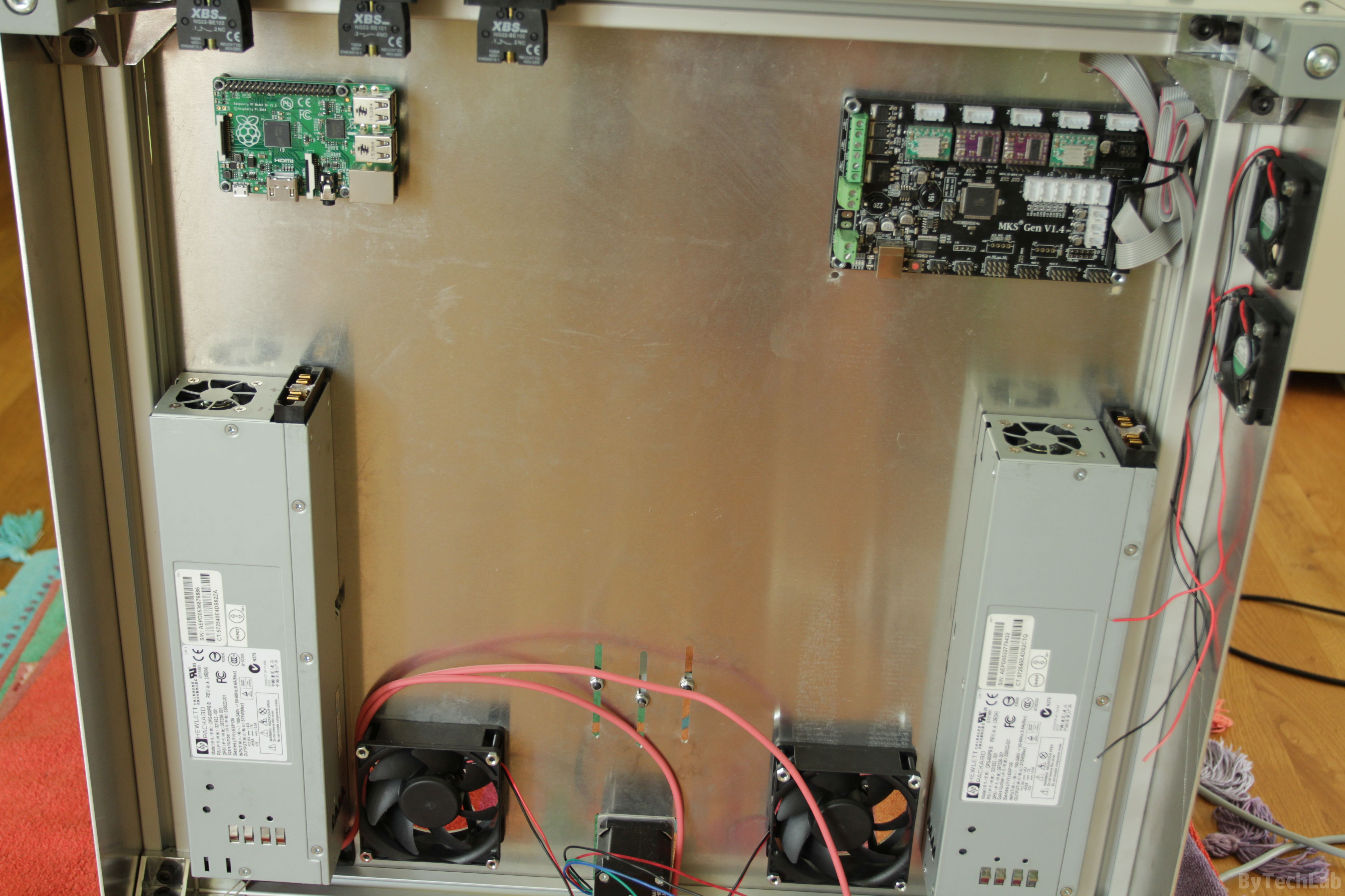
Electronics will be quite complex, the main goal is to achieve high reliability. All wires are neatly and aesthetically laid. I’ve used two HP DPS-600PB server power supplies to provide the 24V power supply rail. They are connected in series with thick copper wires after previous internal modifications. I want to say right away that these power supplies are quiet (much quieter than the original fan supplied with the hotend from E3D). There is one pin which makes it possible to easily reduce the fan speed by shorting it to ground. Without modification, the connection of such power supplies may result in a fire (You are creating an ground loop) therefore I don’t recommend such modification to inexperienced people !.
For switching the current for the heated bed, I’ve used the MKS Mosfet module which is connected to the rest with thick silicone coated wires (I don’t remember exact diameter / cross-sectional area). The 3D printer controller is MKS Gen 1.4 it is quite standard (based on Atmega 2560 MCU ). It works quite well – it doesn’t slow down when browsing the menu at higher printing speeds, so I don’t need anything “faster” yet.
As an print server I used Raspberry Pi 2 with a Wi-Fi module. It is powered from a separate power supply so that in the future it will be possible to remotely turn the printer on and off. There is a Repetier server installed on the Raspberry Pi. There are still several wires that hang from the bottom plate that are not used yet . These additional wires will be used for the laser module and for the support material printing system or something else that I haven’t thought on yet. An additional custom PCB with all additional functionalities will be added soon to the main electronics.

I started assembling electronics from laying main power wires.I have also planned how to sort out the rest so that everything is nice and tidy. Pushing wires through the cable carriers required some effort, but after several dozens of minutes everything went well without any problem. After laying the wires, I’ve cut them down to the right length. Then I have crimped all the connectors on them. All wires are routed down along the rear wall of the plexiglass, in which there are holes for attaching them with cable ties. The cable harness is passing to the bottom of the printer through the holes cut in the bottom aluminium sheet. All cables on the bottom of the printer have been secured with cable ties combined with self-adhesive cable tie anchors.
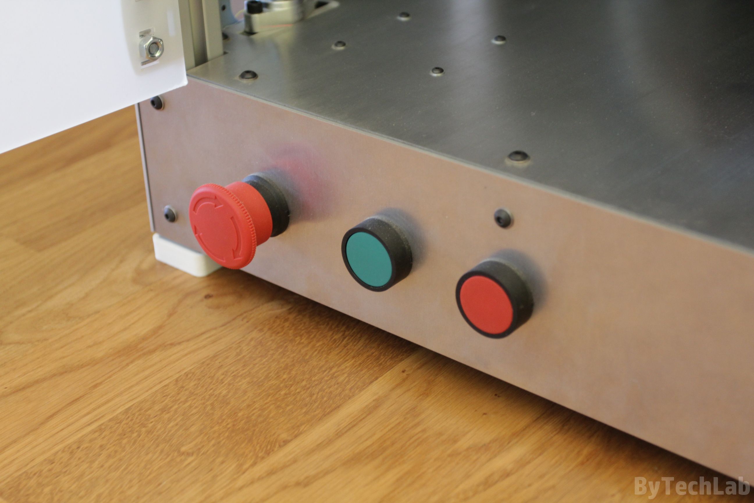
On the front I have mounted a standard graphic display with an encoder and SD card slot (It is an :”RepRapDiscount Full Graphic Smart Controller”). The wires from the display required an ferrite bead in order to suppress interference from high-current wires. Additionally,I have attached nice big industrial buttons to front plate:
- Emergency switch to shutdown the printer in a critical situation
- Red button to pause printing
- Green button to resume printing

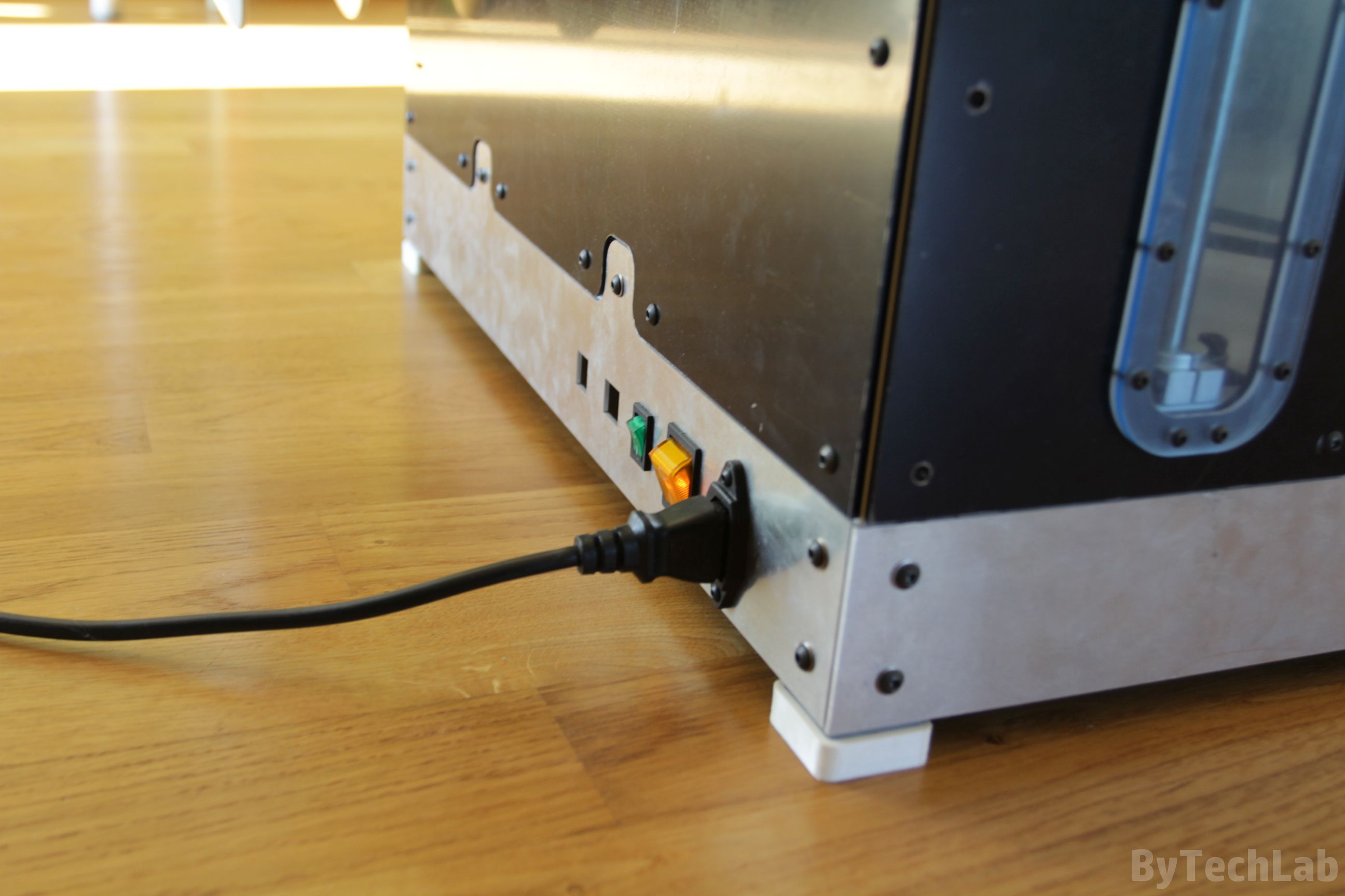
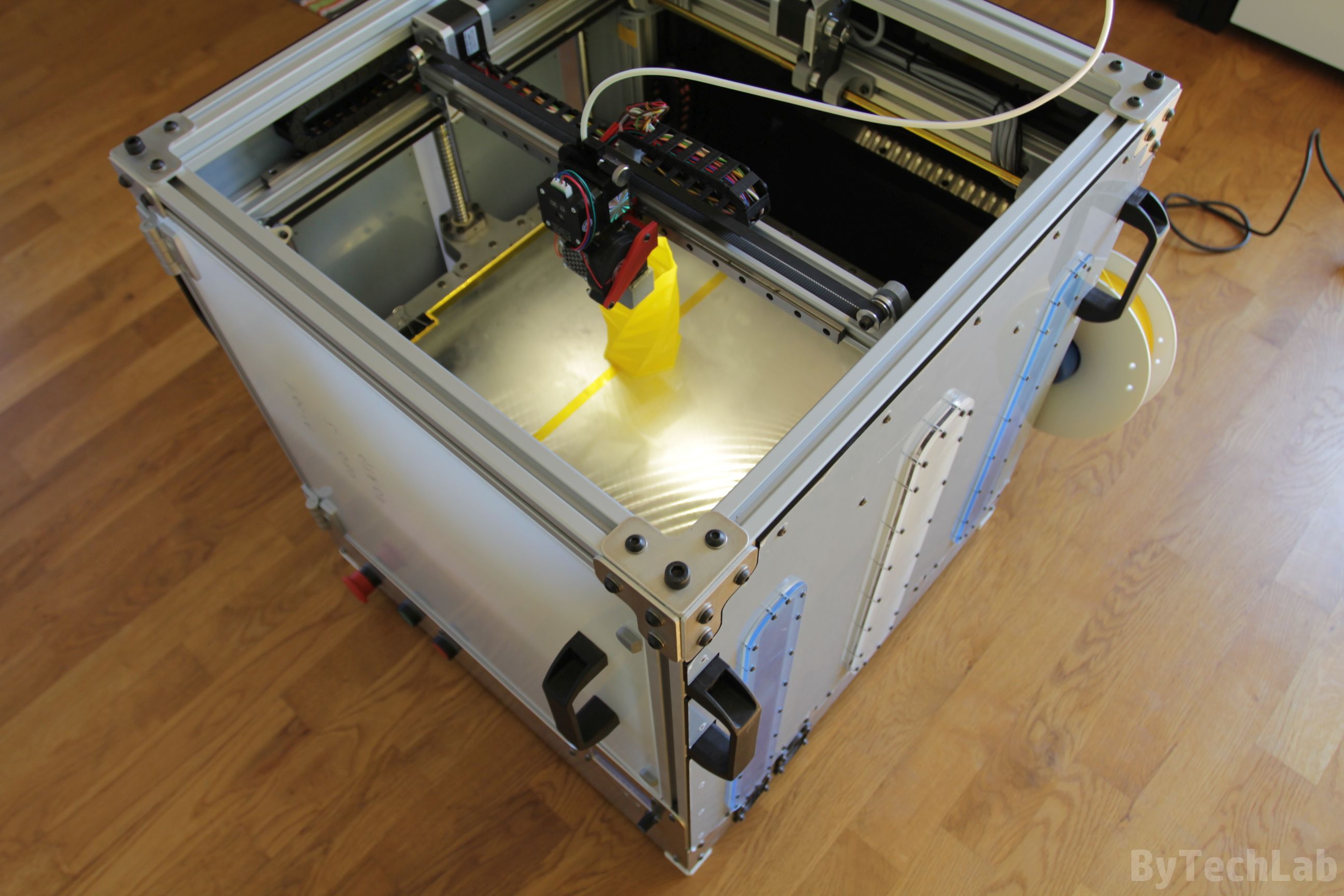
In the picture above you can see the printer during the first run 🙂 . In addition, I’ve designed a nice panel on the back of the printer with integrated switches for turning led’s and power supply on and off. There is also mains power connector of course.
Heated chamber and circulation of heated air
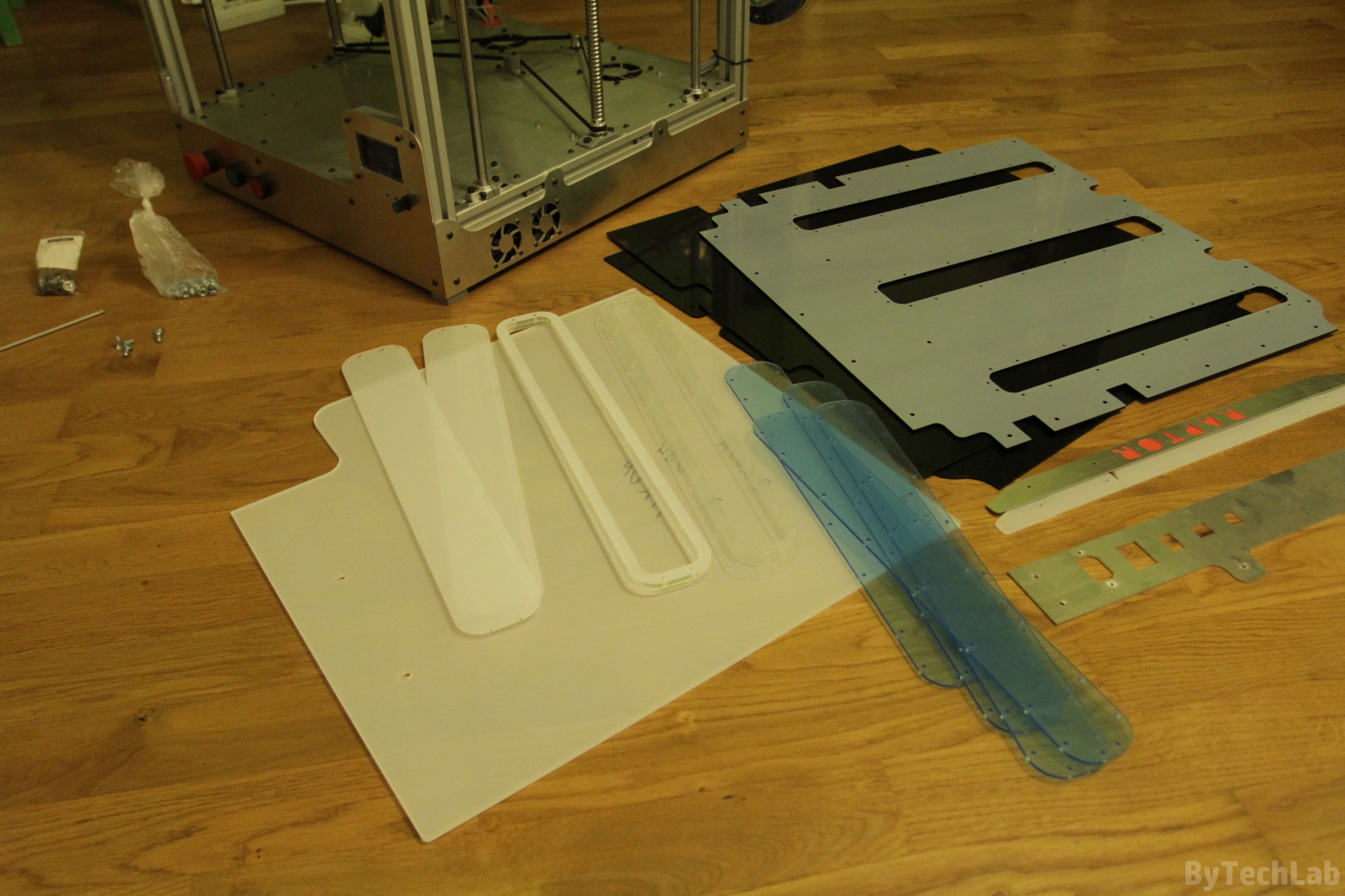
The main chamber was closed with 3 mm thick black plexi panels that were cut with a laser. Only the front door is made of transparent plexi that is 4 mm thick . All of the plexi panels that are visible in the pictures still have protective foil on them so you can’t see their actual colors.
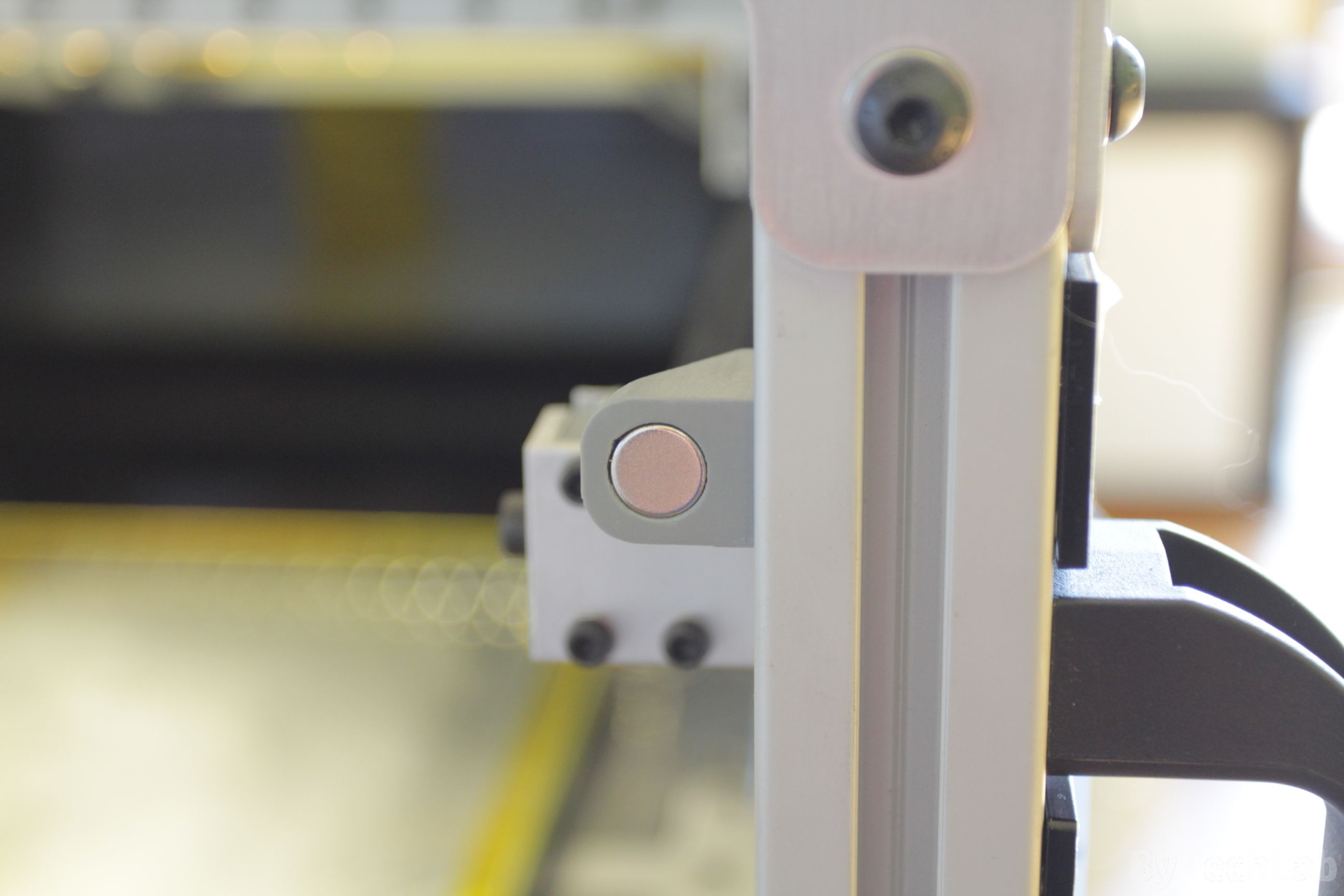
I’ve solved the problem of Z-axis platform mounting brackets that are sticking out from main frame by making windows in the side panels.These windows are closed with transparent plexi panels that have some plexi spacers under them. These windows look quite nice when I turn on the LED strips inside the chamber – they just look like portholes on the ships. The windows can also serve as an Z-axis level indicator almost like a water level indicator in a kettle 🙂 . All windows are bolted down using M3 screws that are screwed into the threaded holes in black plexi panels. In the picture above, you can see the air inlets from which warm air will be blown into the chamber. They have bolted down air deflectors printed from black ABS that will distribute air evenly over the whole chamber.
Chamber heaters will be located above the fans and under the bottom aluminium plate. The chamber heating system will be probably implemented on an additional custom PCB along with other subsystems. On the picture above, you can also see the Z-axis timing belt tensioning system.
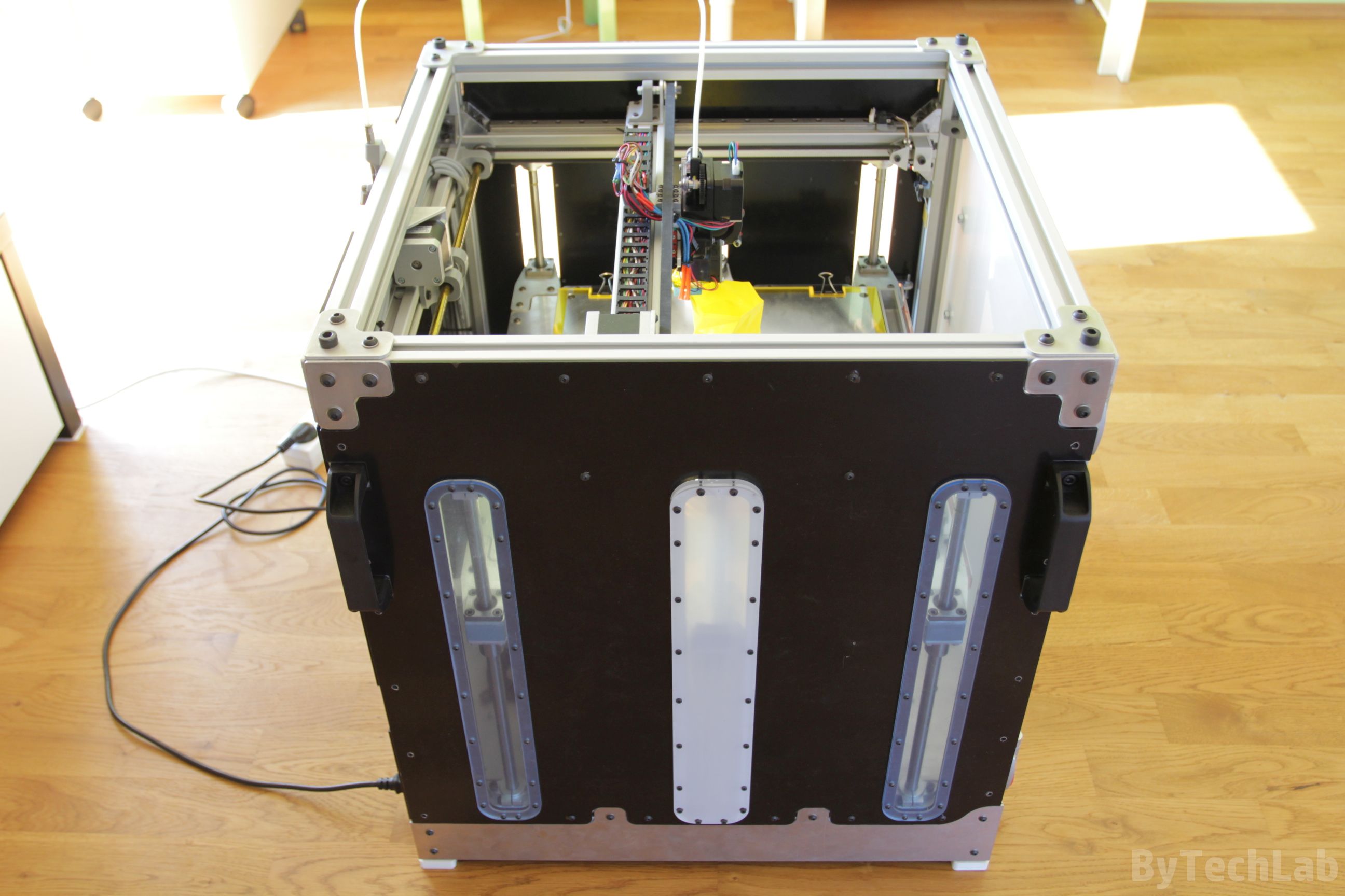
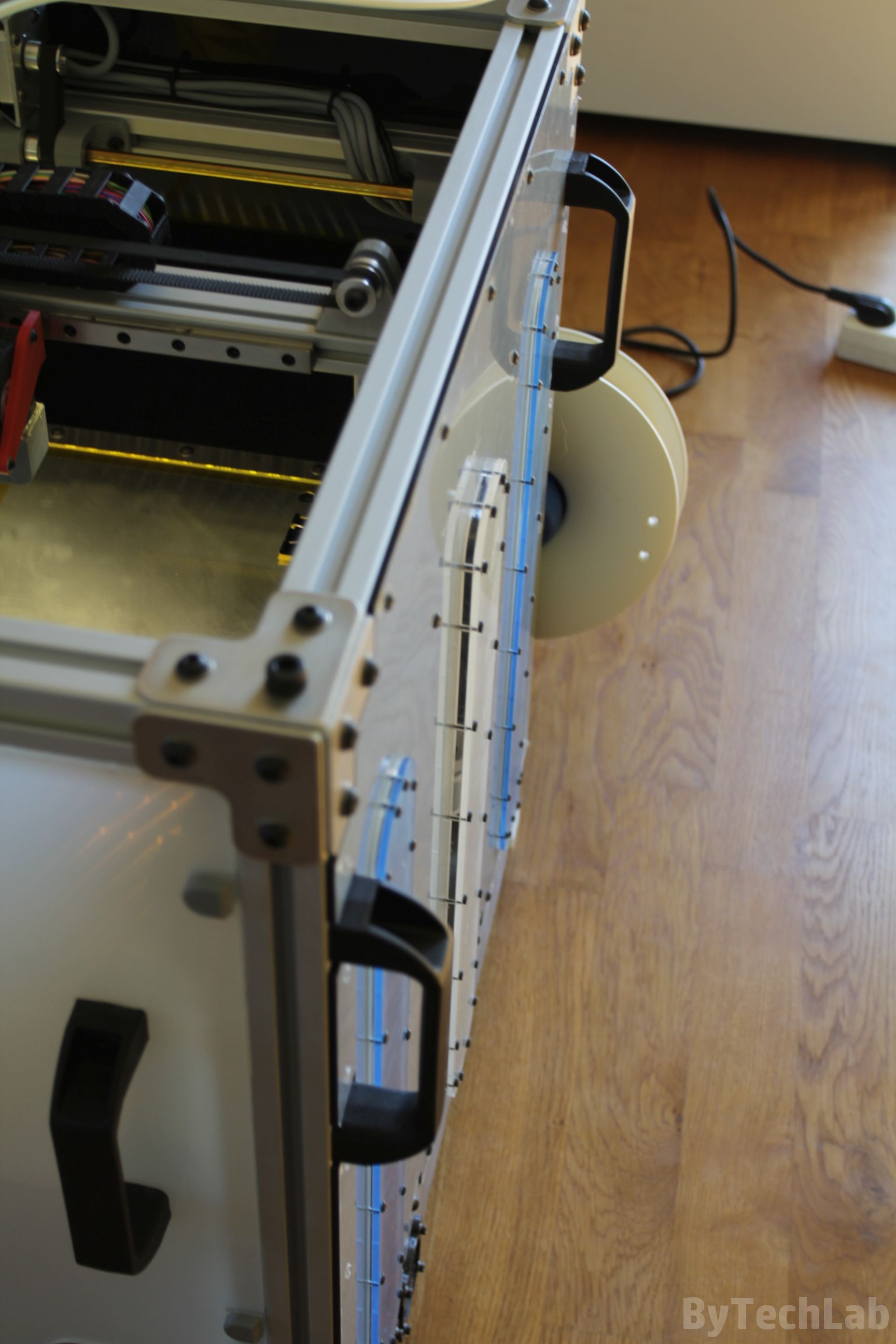
I have applied neodymium magnets to the front door and the frame. Because of that this door will be closing by itself every time you open it. The handles have been bolted down to the frame on each corner to allow me to move this heavy monster to anther place. I have also printed two filament holders which are bolted to the back of the printer. In addition, as you can see in the pictures below, I’ve printed rubber feets using white TPU filament to reduce the noise generated by the printer.

Extruder and hotend

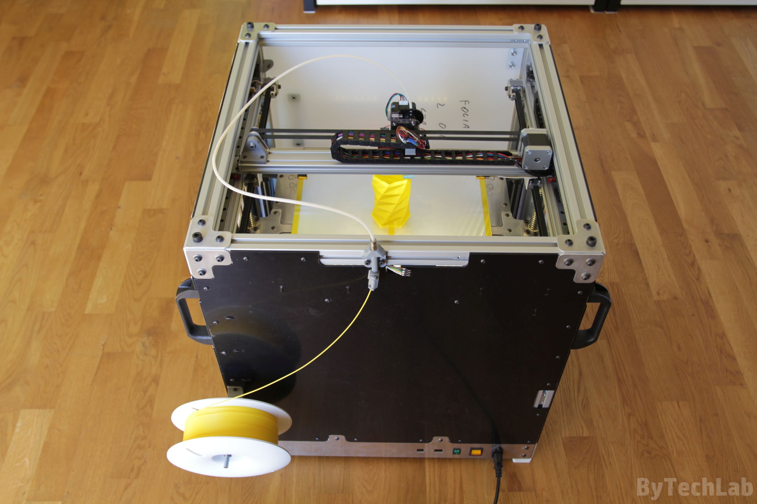
At the beginning, the printer was equipped with a bowden extruder with a 3:1 gear ratio that used a timing belt gearbox (you can see it on the pictures below). Unfortunately, as it turned out with such a long bowden tube (about 900 mm) and a 1.75 mm diameter filament, it is practically impossible to maintain constant pressure in hotend (filament is compressed and the PTFE tube is stretched). Only a hotend compatible with a 3 mm diameter filament could work in this situation.
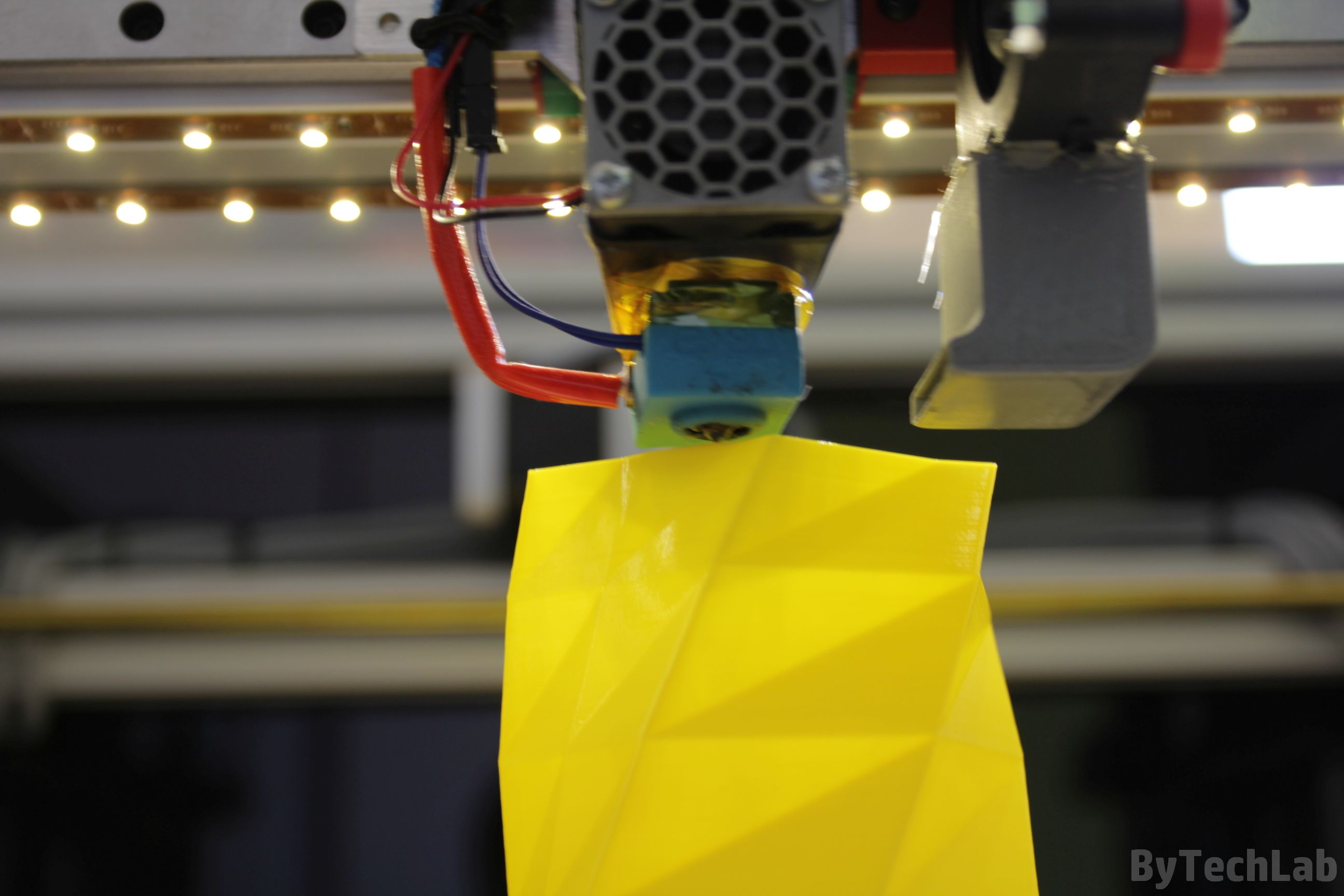
That’s why I’ve decided to redesign the whole extruder assembly and switch to direct one. As an extruder, I used new Titan from E3D together with V6 hotend also from E3D. On the heating block there is a silicone sock from E3D that isolates and protects it from melted filament. A pancake motor (Nema 17 ,400 steps per revolution) is installed on the extruder in order to eliminate the effect of uneven extrusion caused by loosing some of the microsteps.
Lighting and endstops

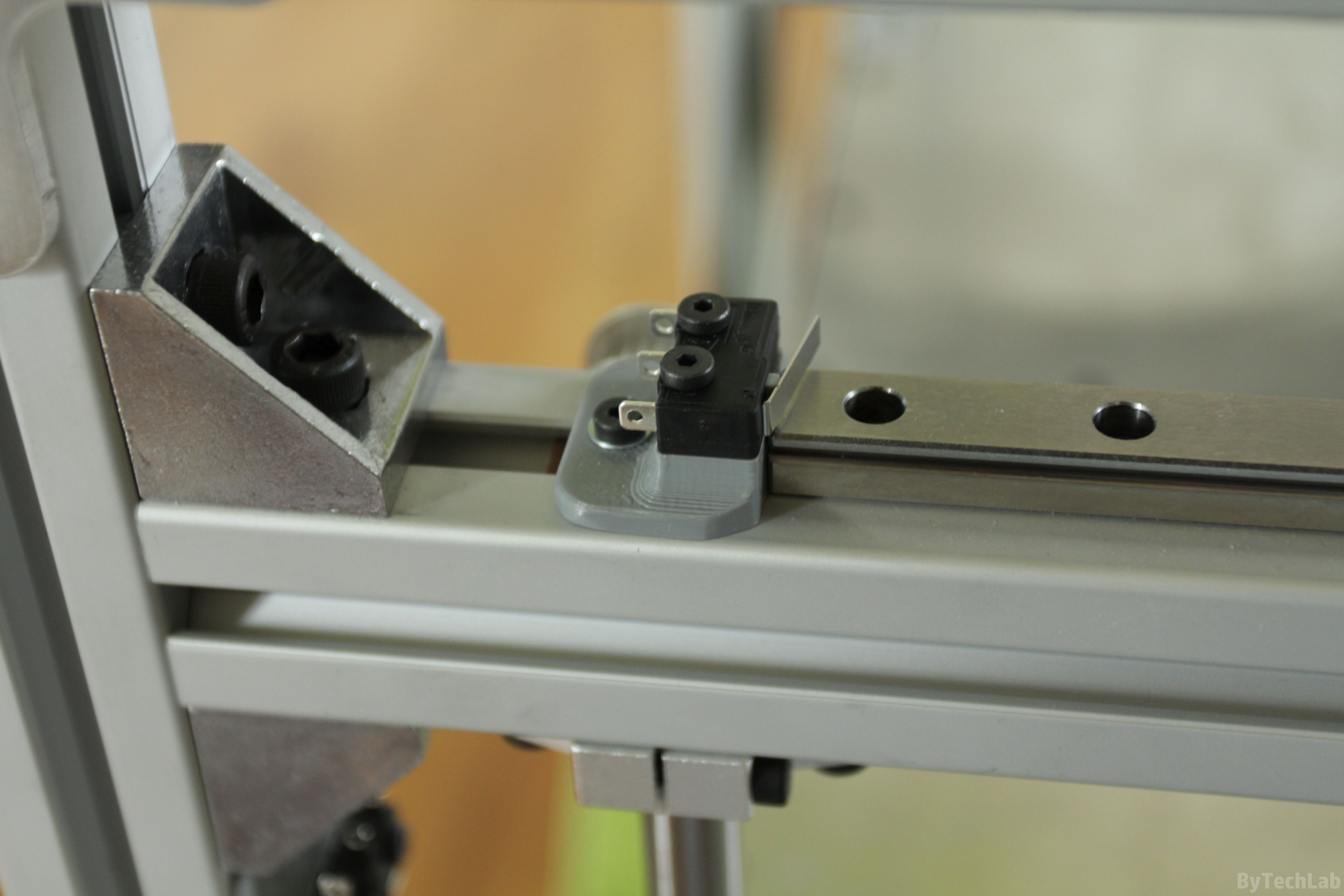
At the beginning I wanted to install LED lighting, also above the front top beam. However, after installing 2 LED strips under the X-axis beam, I found that I don’t need more LED strips to light everything up. In order to improve appearance of this printer I installed a neat laser cut aluminium panel with printer name embeded into it . Under this panel there is matted plexi that diffuses light from a red LED strip. Unfortunately, I forgot to make small tabs that would hold internal parts of letters in place. All endstops in this printer are quite standard – ordinary mechanical switches. Over Z axis endstop I have installed a bolt that is used to change homing offset in this axis.

Additional features
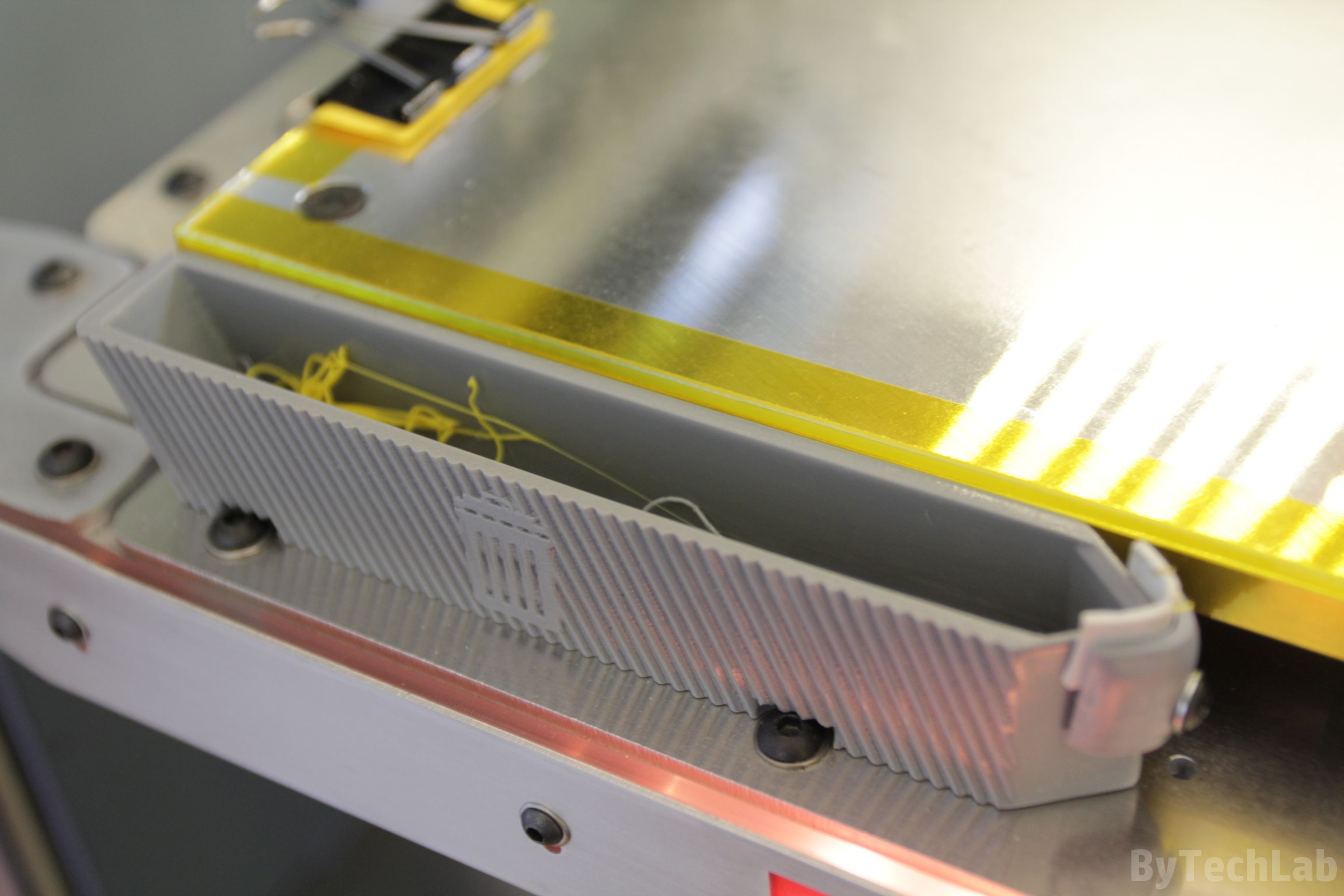
One of the additional features that are currently installed in the printer are small trash-bins.They allow to extrude out an old filament while warming up the hotend. The nozzle can be wiped out with a rubber band located at the end of the trash bin. Thanks to this, I don’t have to wait with tweezers until the printing process starts in order to remove any hanging filament residues from the nozzle.
As you know, these melted filament pieces can seriously damage first layer. In the middle there is also a carbon sponge that nicely cleans entire nozzle from melted filament. In commercial / professional printers, these trash bins have been used for a long time, but in “reprap” printers, this is a relatively rare element.
General printer parameters
- Build volume [XYZ]: 360 x 360 x 360 mm
- Printer weight ~ 40-50 Kg (I don’t really know how much it weighs ,because I can’t move it anymore because it is too heavy)
- External dimensions: ~ 58 x 58 x 63 cm
- Power consumption 800-900 W peak
- Two 1605 ball screws and four linear shafts Ø12 mm in the Z axis
- Printing server: Raspberry pi 2 + Repetier + WiFi + Camera
- “Electronics”: MKS Gen 1.4
- Hotend: genuine E3D V6
- Extruder: genuine E3D Titan
- Genuine HIWIN linear rails and bearing blocks in X / Y axis
- 400 step per revolution motors on all axes, including the extruder
- Power supply with a total power of 1.2 kW @ 24V
- Structural Z-axis platform with a maximum thickness of ~ 28 mm
- Heated chamber – in the near future 😉
- Fully closed chamber
- Frame made of 30 x 30 mm aluminium extrusion profiles, steel and aluminum
- GT2 timing that are belts 9 mm width
Features and parts that are not finished yet
- Actively heated chamber with air circulation
- Laser module for engraving
- Support material printing system
- Time lapse camera connected to print-server
- Turning the printer off and on remotely
- Voltage stabilizing module for stepper motor controllers with high internal capacitance
- A good two-sided fan duct for cooling prints connected with 2 blowers
- Filament sensor
Summary
I am very pleased with this printer, I wouldn’t exchange it for anything else 🙂 . I did everything exactly as it should be done. I think I can say that it is one of the largest and the most “bulletproof” 3D printer in the world 😉 . I hope that this article was interesting for you and as always I encourage you to post comments below. In the near future when this printer will be finished in 100% I will publish more articles/posts about it .
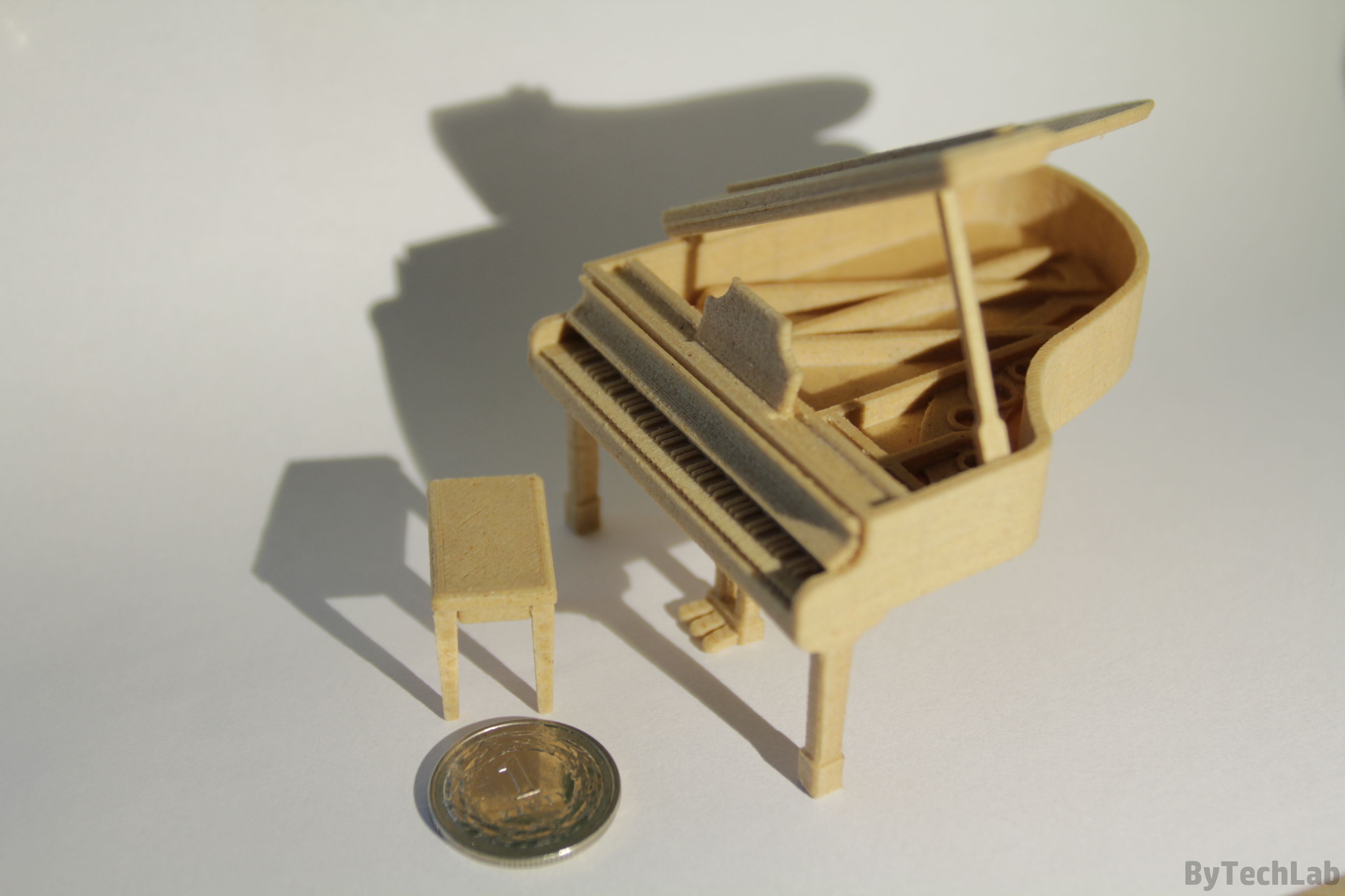
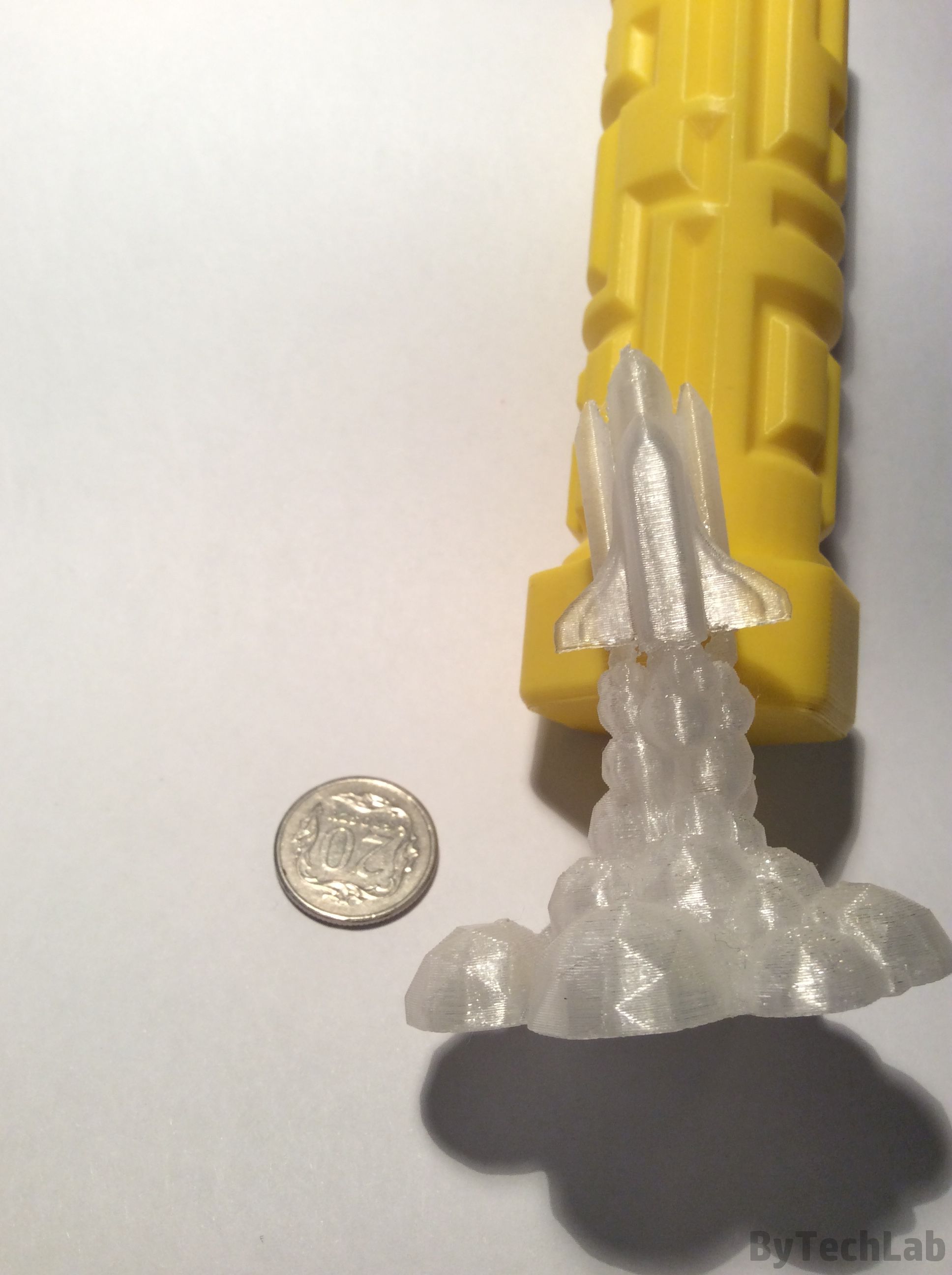
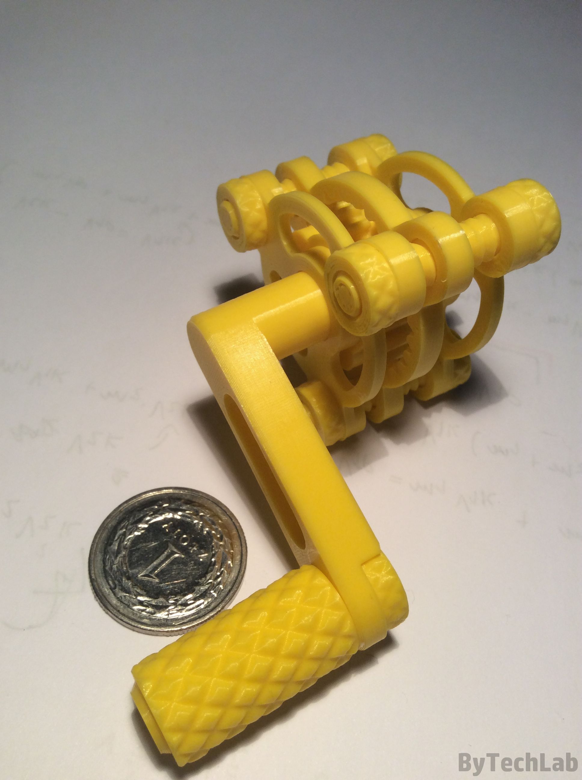
In addition, below I have uploaded additional photos of some of the 3D prints that came out from this “little” monster:
Additional photos
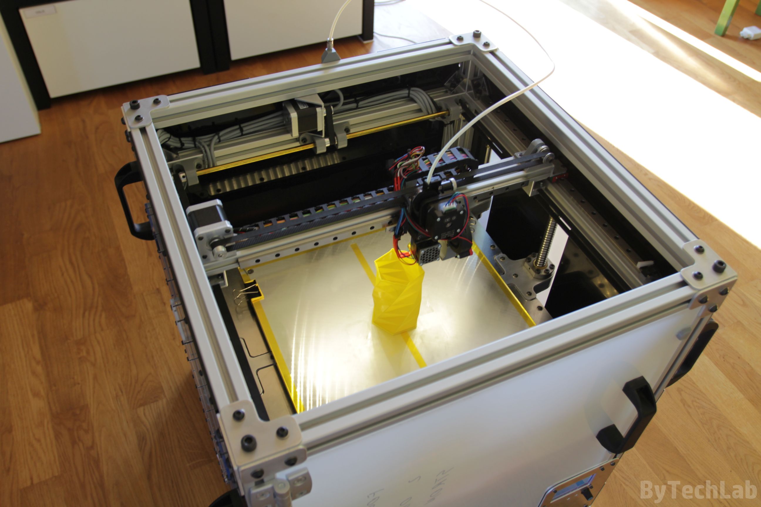
Sample 3D prints

As always, you can post comments down below↓↓ (If you have any questions feel free to ask):
Don’t forget to like, follow and subscribe ByTechLab on other websites: