Recently I have started a phased array FMCW radar project. I needed good antennas for this purpose but I haven’t decided which frequency to use yet. That’s why I have decided to choose a wideband antenna – I will be able to switch between different frequencies if needed. Also such a general purpose antenna can be used for other projects. I have chosen a 3D printed double ridged horn antenna mainly due to interesting construction ,great performance and low manufacturing cost (commercially available solutions are extremely expensive). The whole antenna was designed to have good performance between 2 – 6 GHz.
In this quite detailed post / article I will show you the whole Research / Design and Manufacturing process. Of course I will not dive into all of the details because the whole process is quite involved and the post would be simply too long to read.
1) Initial simulations – Research
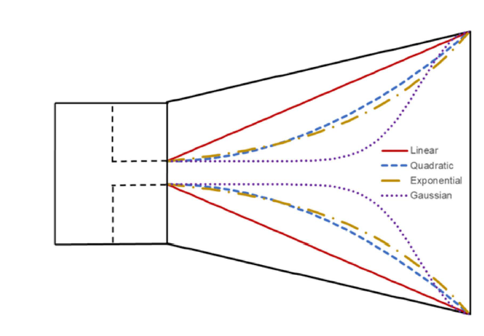
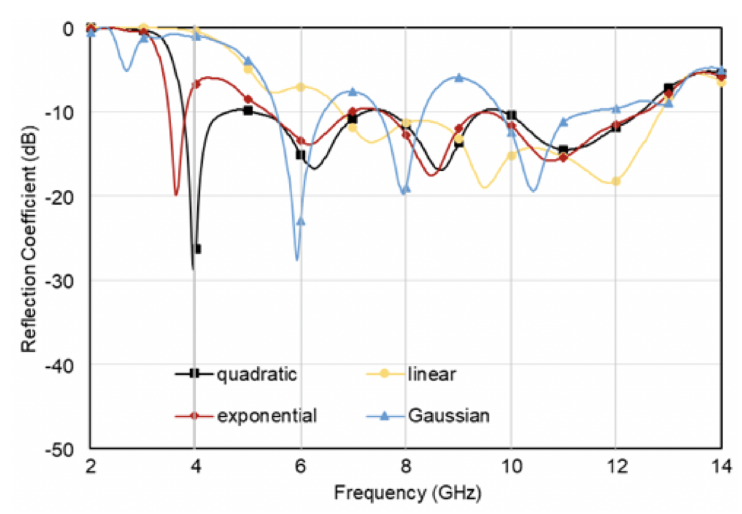
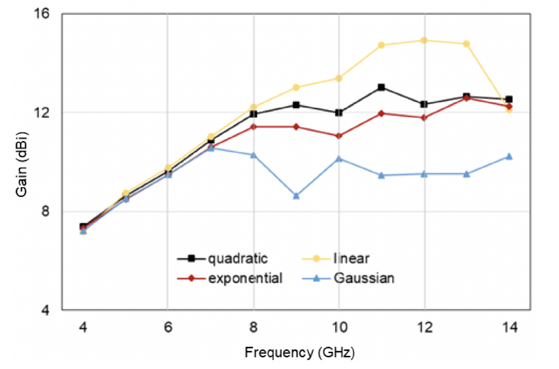
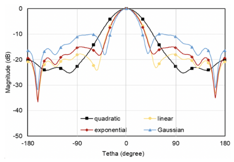
After I have chosen the antenna type I have started researching the topic. Of course the first places where I started looking were papers and books. I was able to find one particular paper that was very helpful in the whole design process of this 3D printed double ridged horn antenna: [1] “Wideband Dual-Polarized 3D Printed Quad-Ridged Horn Antenna” . The most important finding was that the ridges in these antennas can have different shapes (Linear, Quadratic, Exponential and Gaussian). Each of these ridge shapes has different properties which impacts the antenna characteristics in several places like: beam width, gain and impedance matching. For FMCW radar I need a antenna with stable beam with no or very little sidelobes, good gain, good impedance matching and as narrow beam as possible. The quadratic ridge profile satisfies all of my requirements (the only thing that could be better is the beam width).
You can find the equation for quadratic ridge shape that will be used to design a parametric 3D model below (2) :
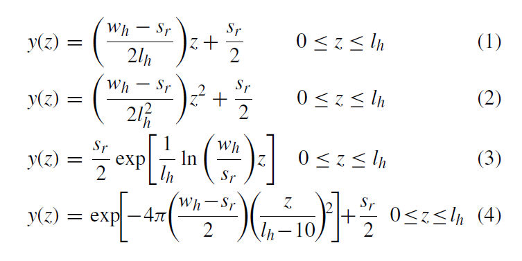
2) Initial simulations – Simplified parametric model
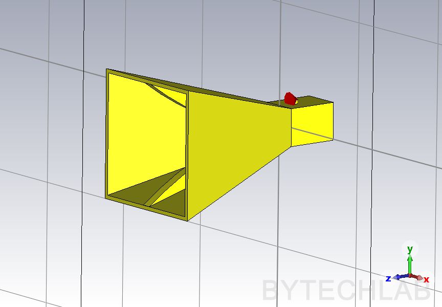
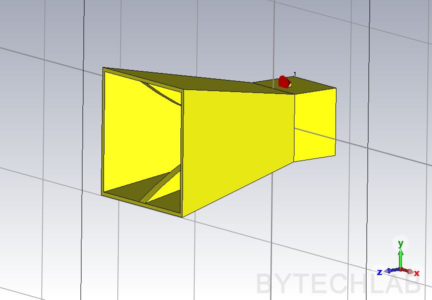
Based on the equations from paper above I have designed a parametric 3D model of the antenna in CST Studio. Every single dimension of this antenna is parametric to make parametric analysis possible ( sweep through different parameter combinations). As you can see on the screens above and below with single mouse click I can completely change the shape of the antenna ( width, length, ridge shape etc.)
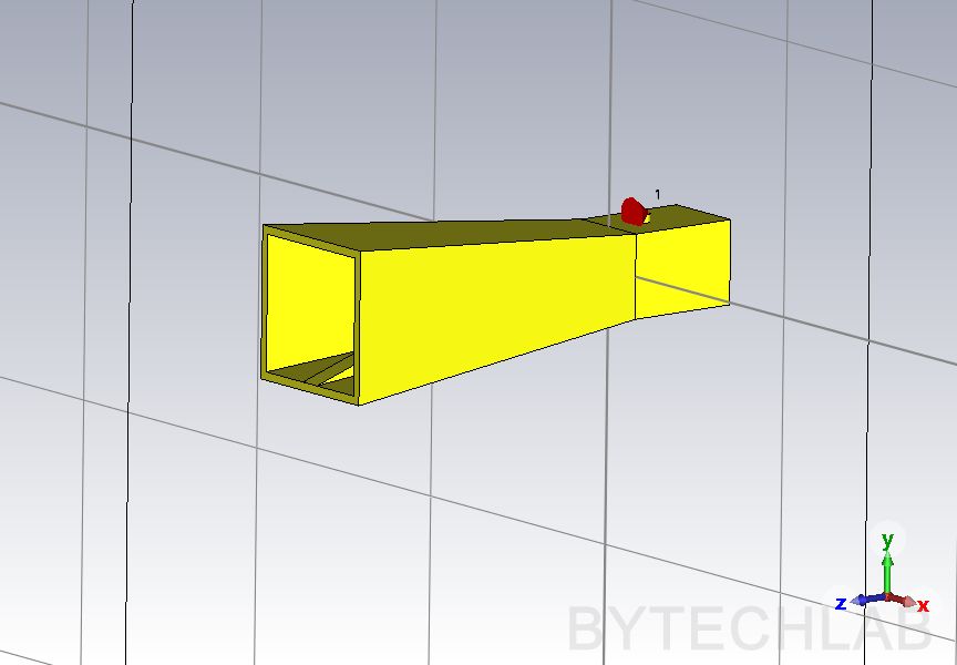
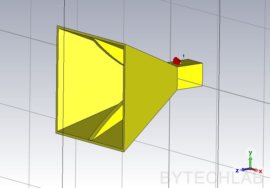
Because of using the parametric approach I was able to quite quickly iterate with the design and optimize every single dimension of the antenna to get as good performance as possible quite quickly. The tricky part is that all of knobs are connected to each other. When you fix one thing ( for example impedance matching) the other breaks ( for example beam shape). Because of this you need to know which dimension of the antenna (which parameter or knob) influences which characteristics of the 3D printed double ridged horn antenna. Of course you could do a brute force approach and simulate all possible combinations and then choose the best one but this would simply take too much time ( each simulation takes approx. 2-3 hours).
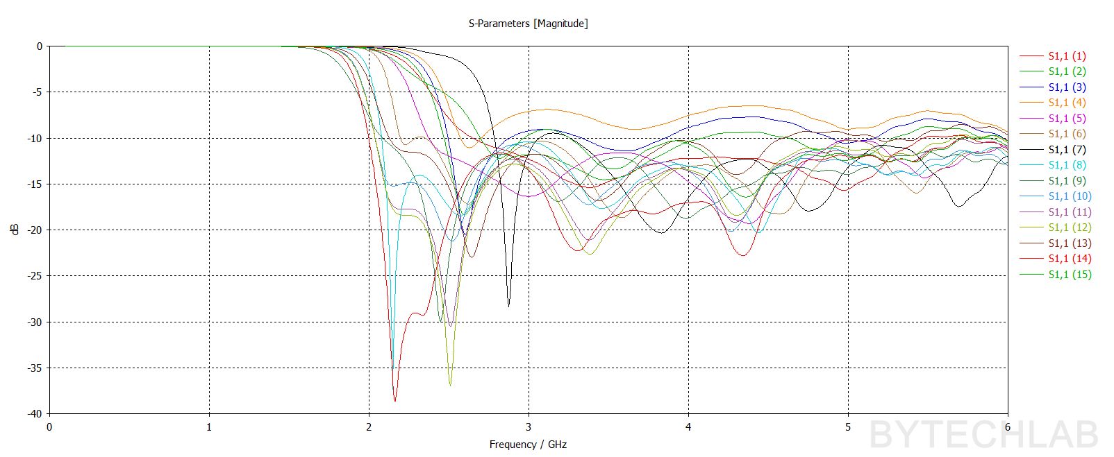
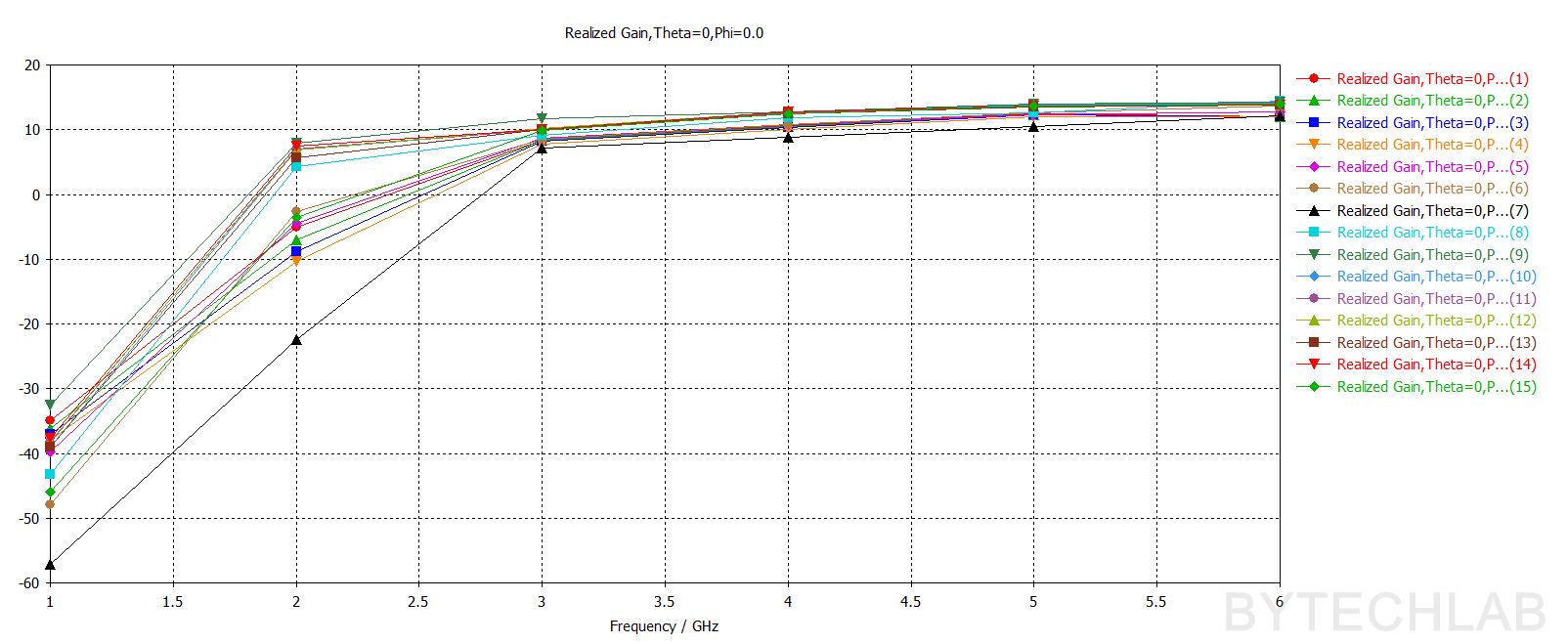
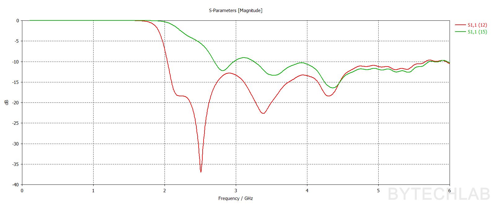
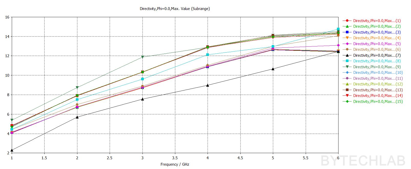
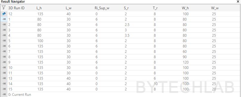
Above you can see some of the results from parametric simulations. It’s easy to see that changing one dimension just a little can change everything. That’s why these antennas usually need very precise manufacturing methods to get good performance and correlation with the simulations. Based on these simulations I have picked one parameter combination that suits my needs the most (3D Run ID: 12). You can see all parameter values for this 3D Run ID in the table below.
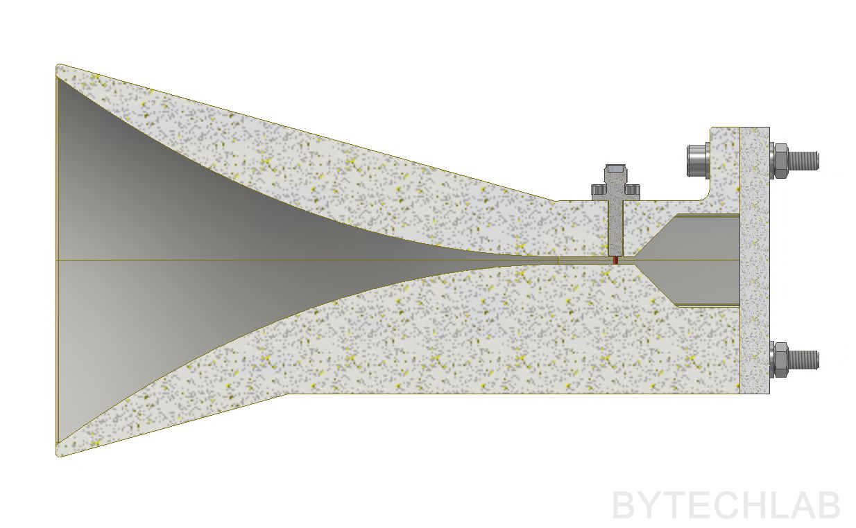
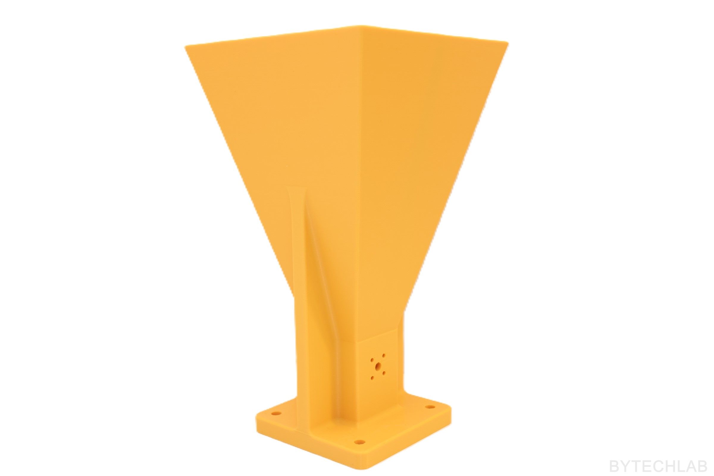
3) Final MCAD design based on simplified model (V2)
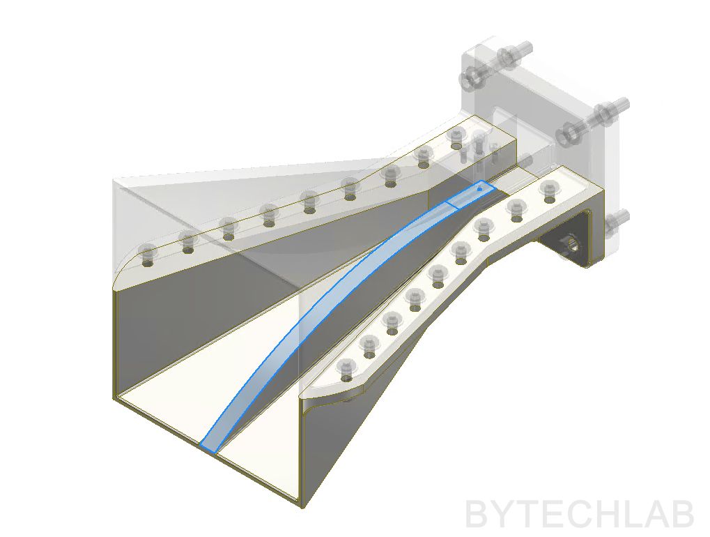
The parametric model from CST Studio is simplified and does not take the manufacturing constraints into account. That’s why I have imported the simplified .STEP model into Autodesk Inventor to change the design and add important features / details. I will describe some of them below:
- I have added ribs on the horn side walls for reinforcement,
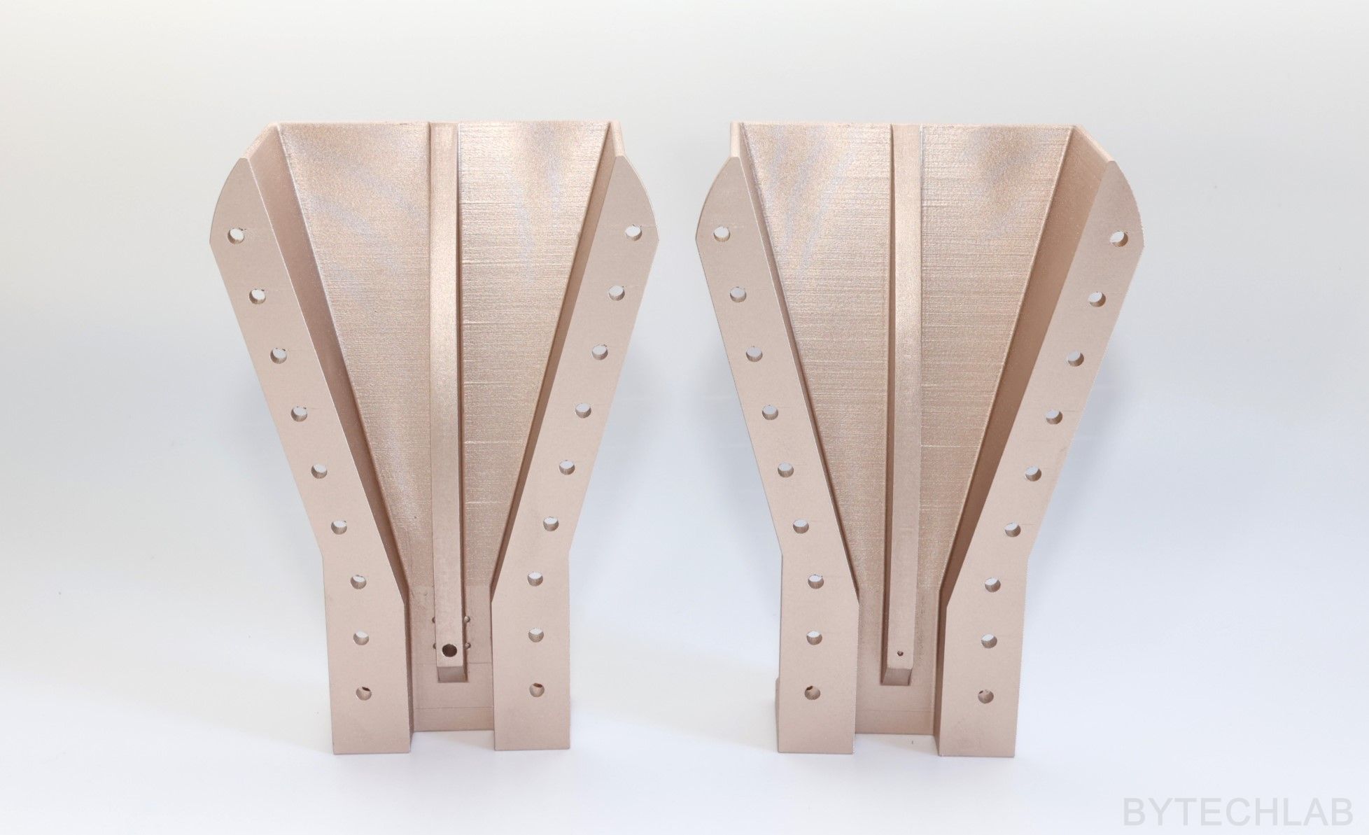
- The model was split into two halves that are mounted together with use of screws to make both 3D printing and metal plating easier (more on that later),
- Antenna was optimized to be printed vertically without supports (chamfers under the ridges were added),
- SMA connector and feed point was added,
- CNC milled aluminium backplate was added,
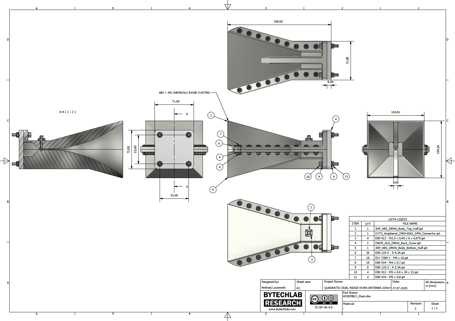
In the GitHub repository (MCAD folder) you can find the following files:
- Autodesk Inventor project of 3D printed double ridged horn antenna,
- Exported STL files for 3D printing,
- Exported STEP file of the whole assembly,
- Exported PDF file with assembly drawing, BOM and assembly instructions,
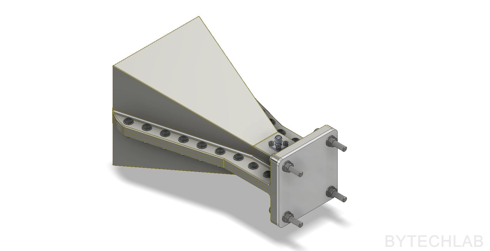
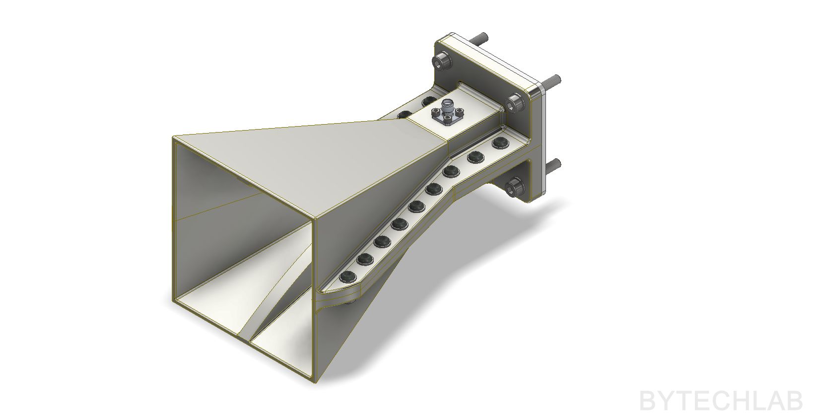
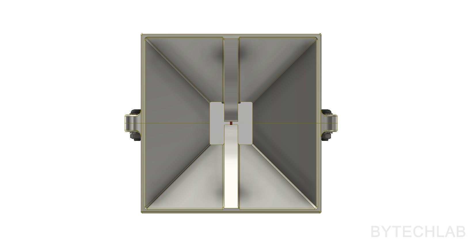
- Exported assembly renders,
4) Final MCAD design simulation
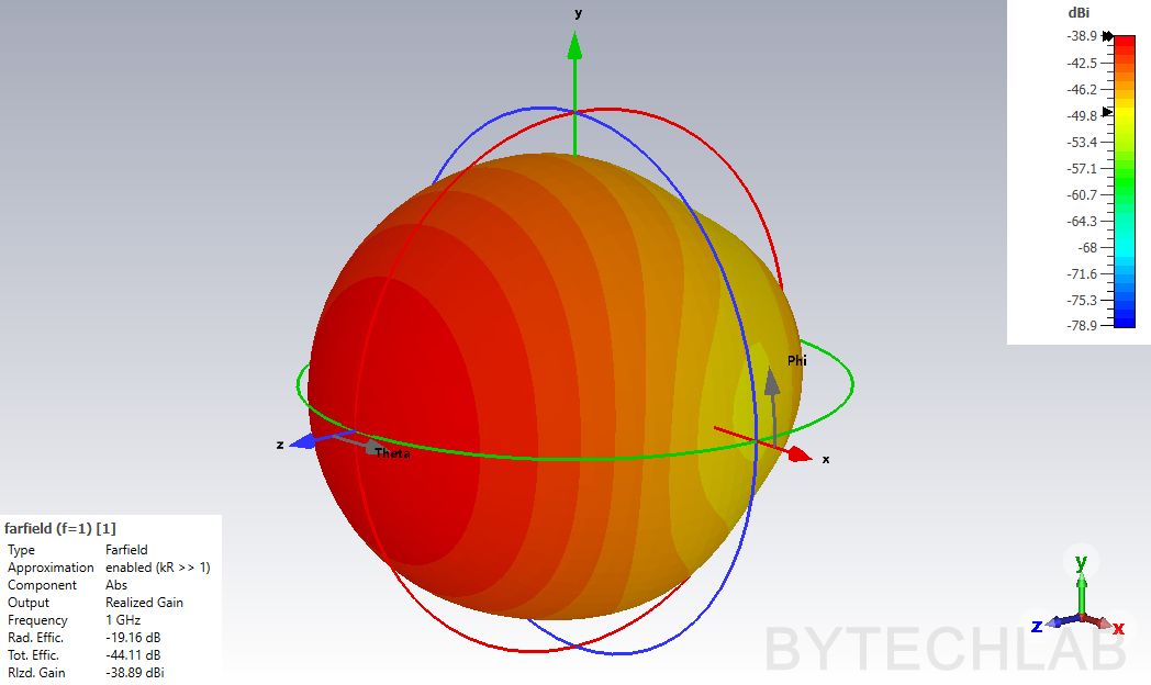
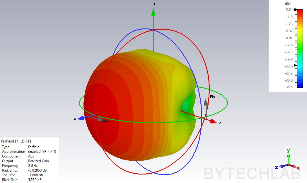
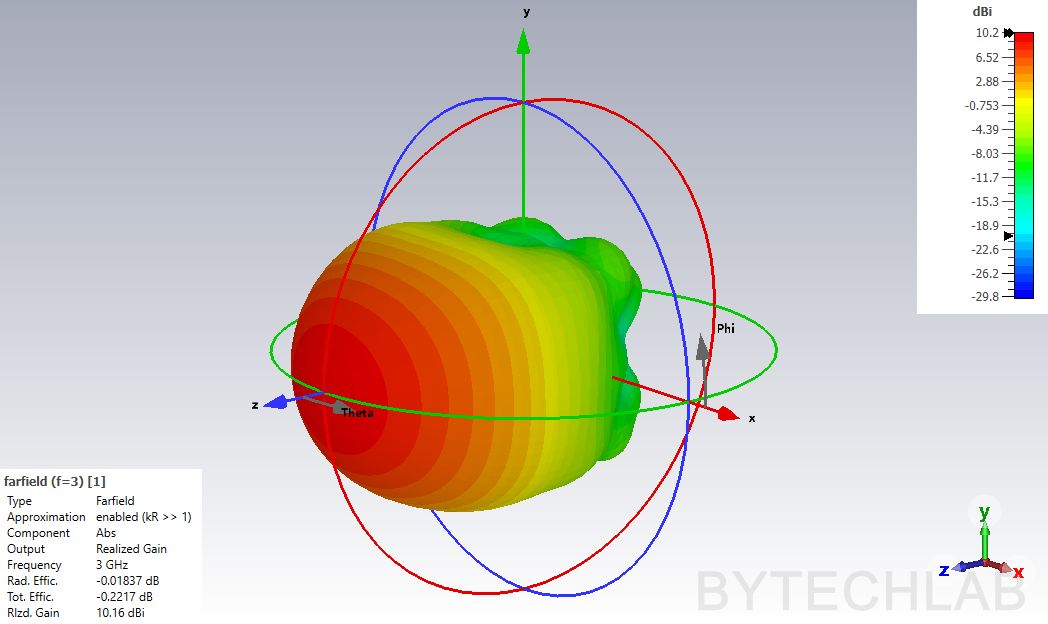
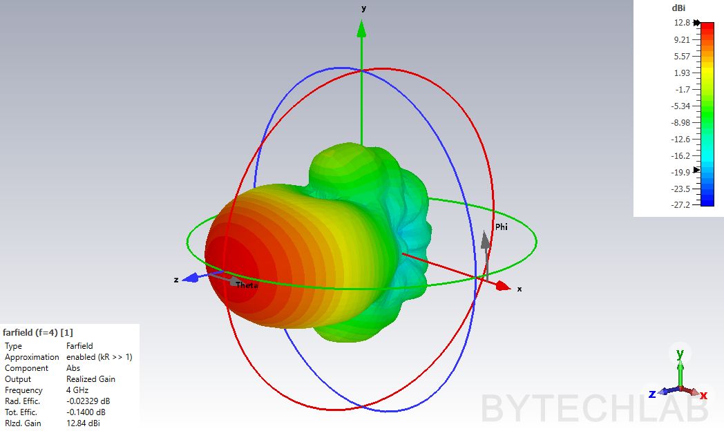
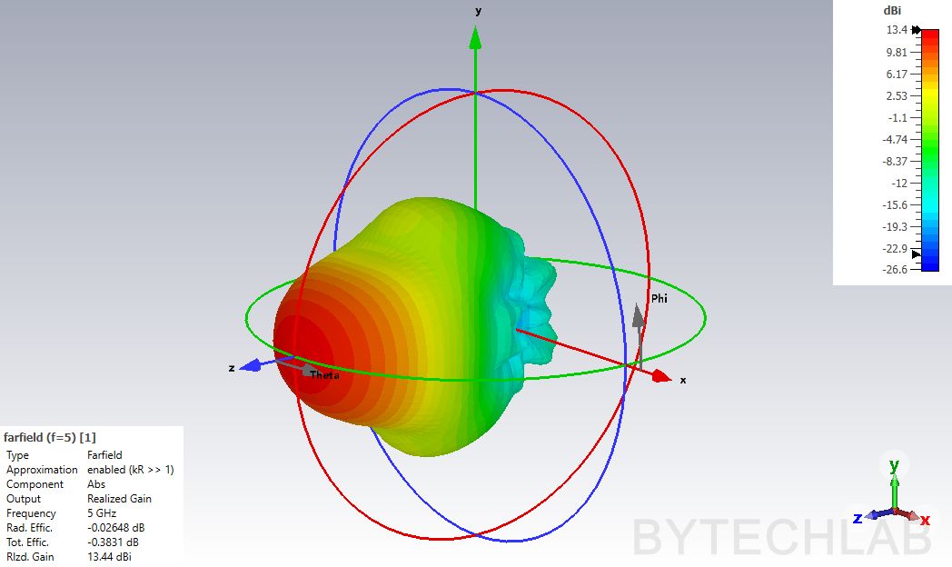
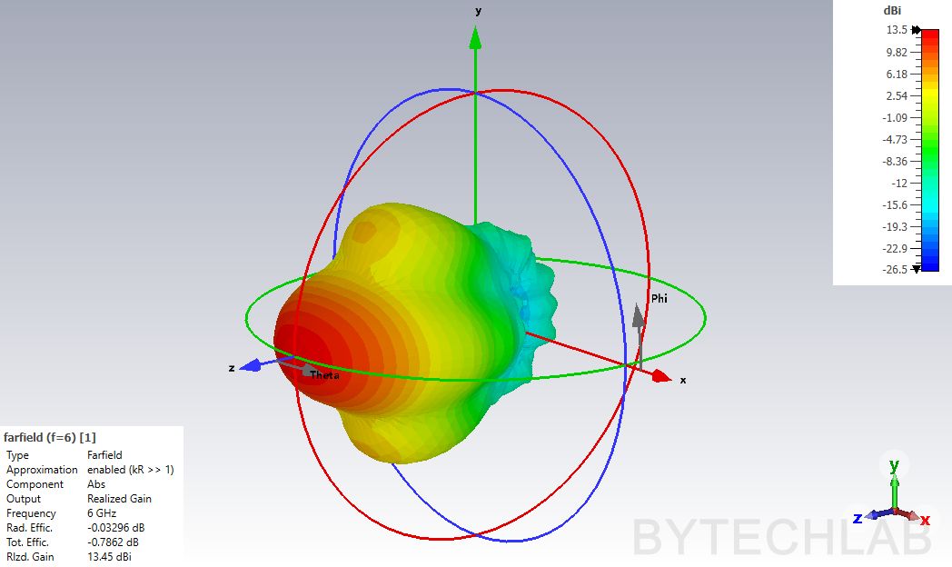
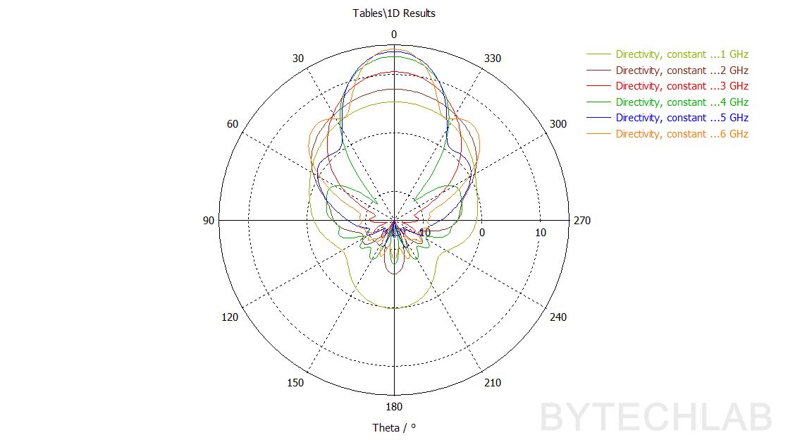
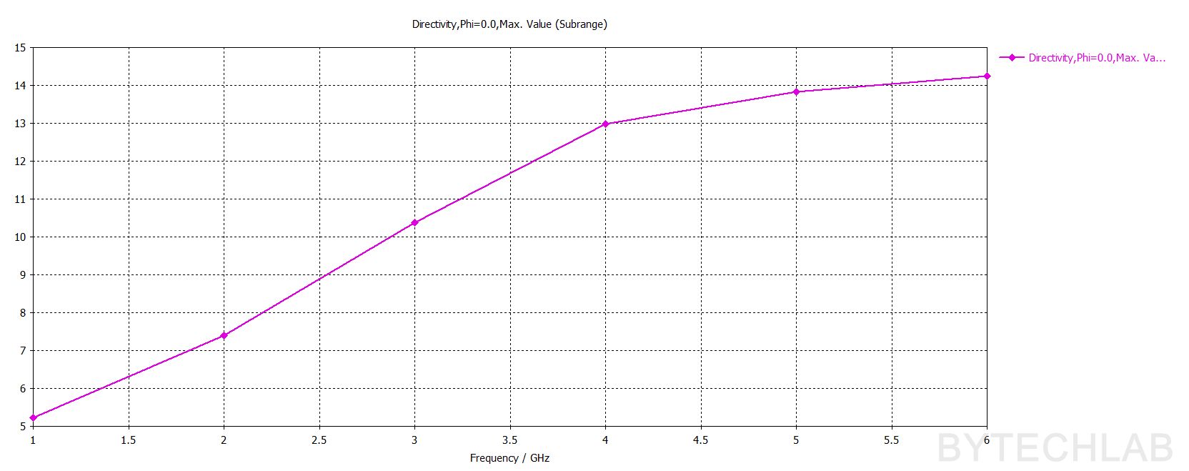
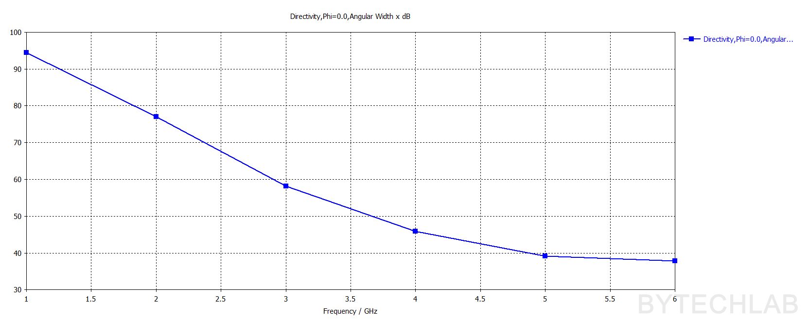
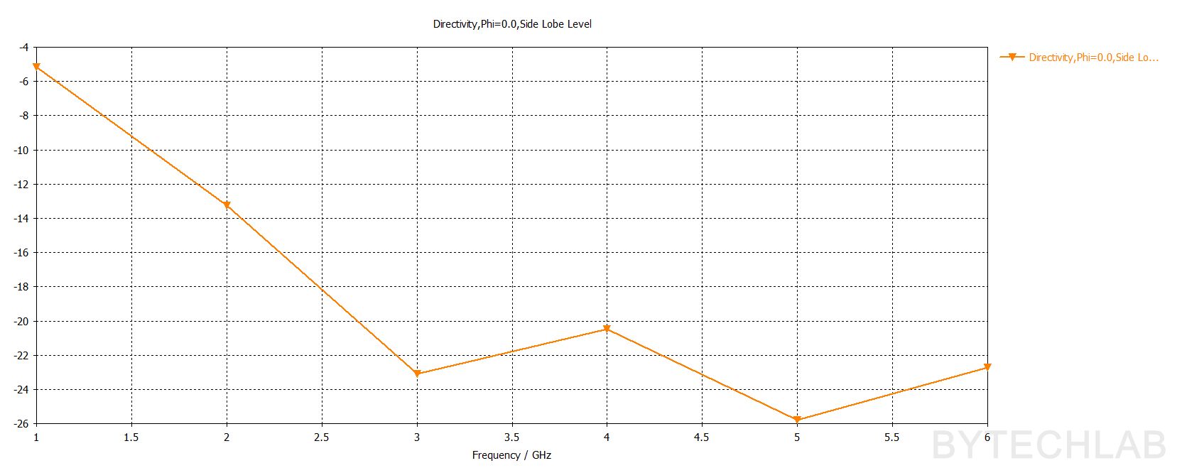
To verify the final MCAD design I have exported it from Autodesk Inventor and imported it back to to the CST Studio. To be 100% sure that this design will work well I have ran full set of simulations. On the above animation you can see the E filed propagating through the antenna at 2.5 GHz and 5 GHz. Below you can see the 3D Farfield renders of the antenna (Realized Gain). When the frequency goes up the beam gets narrower and narrower. For the upper frequency limit (5- 6 GHz) you can observe some sidelobes forming.
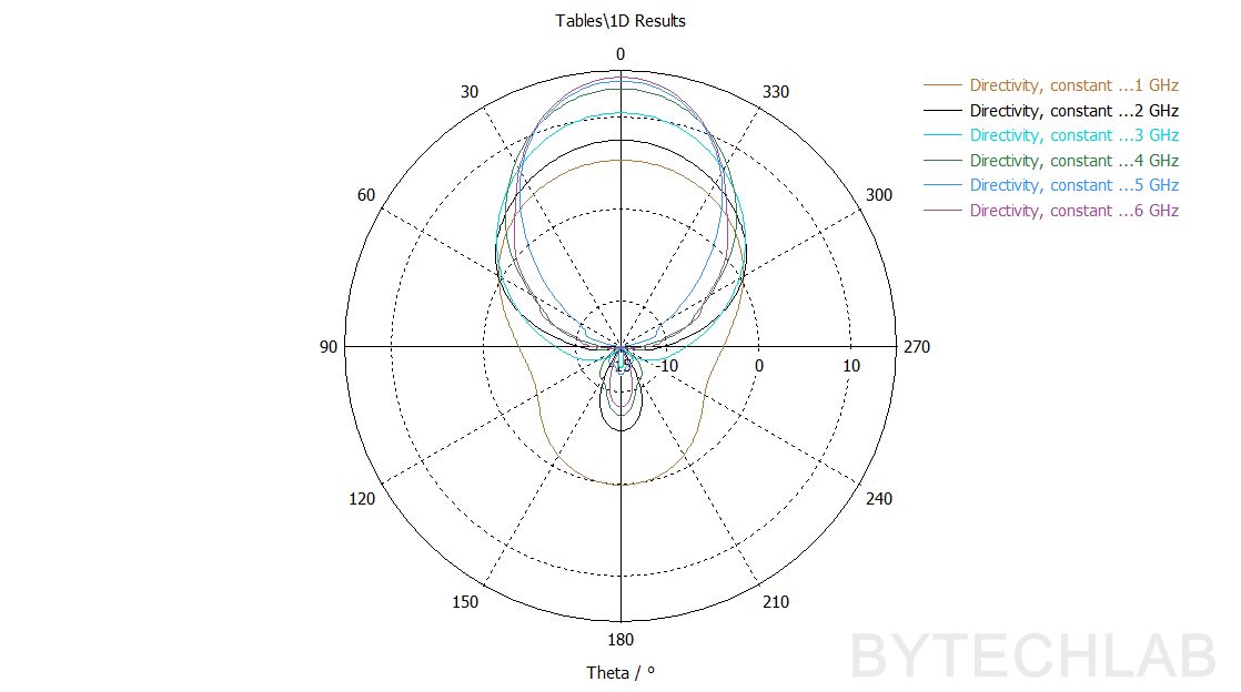
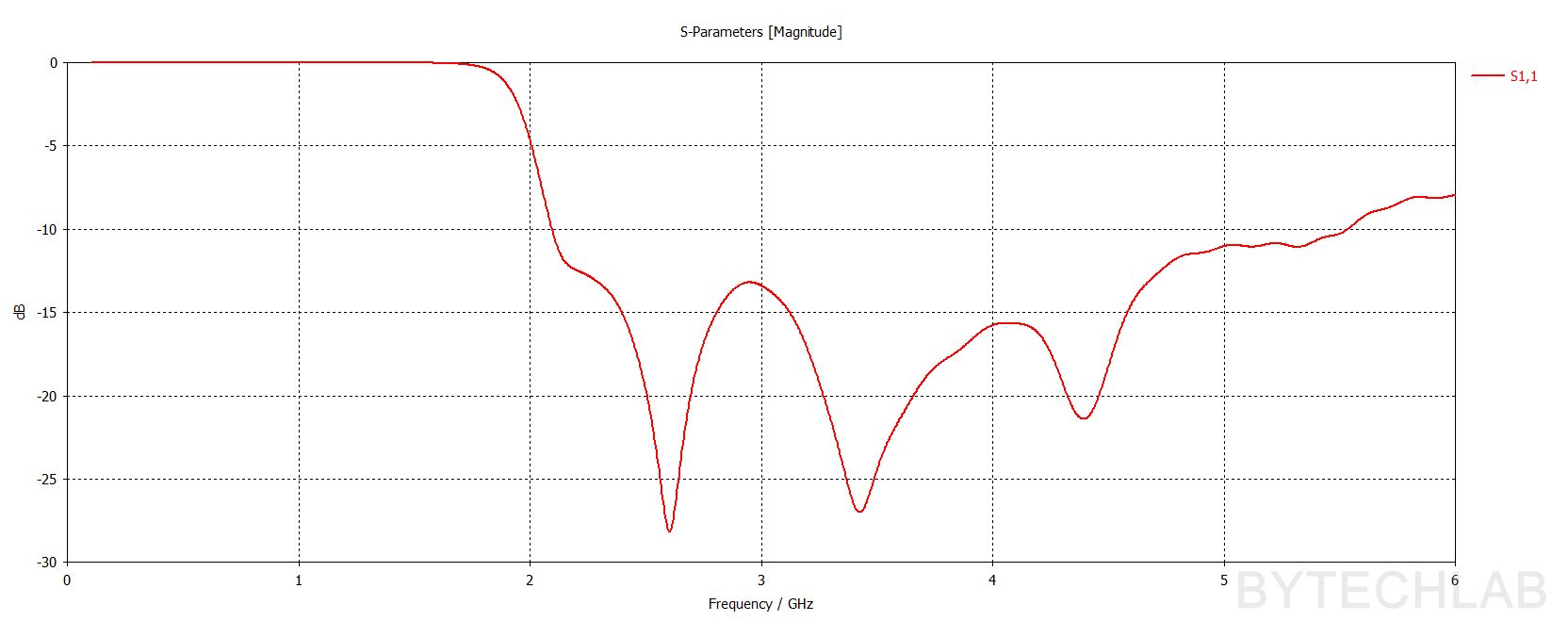
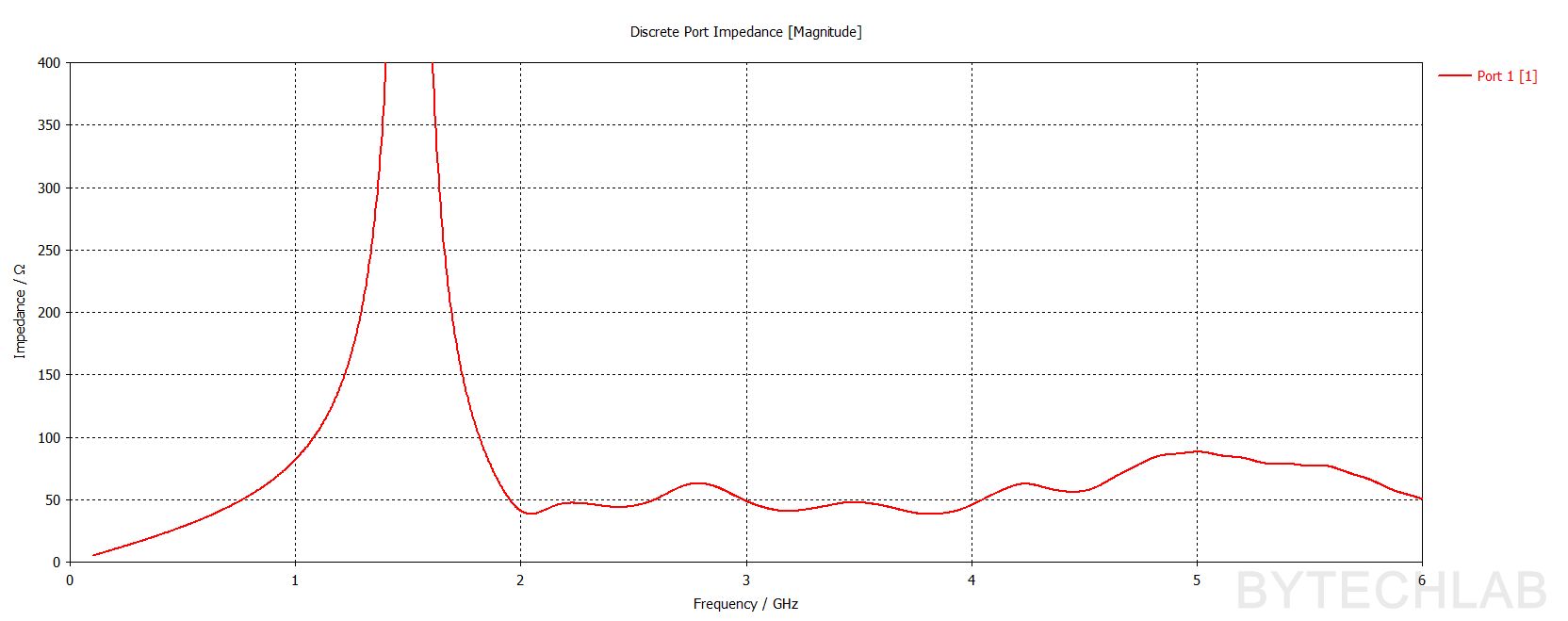
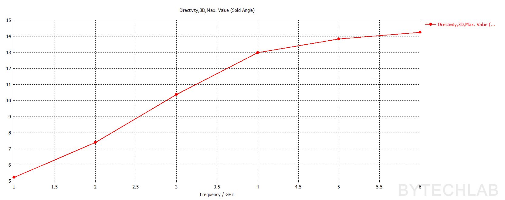
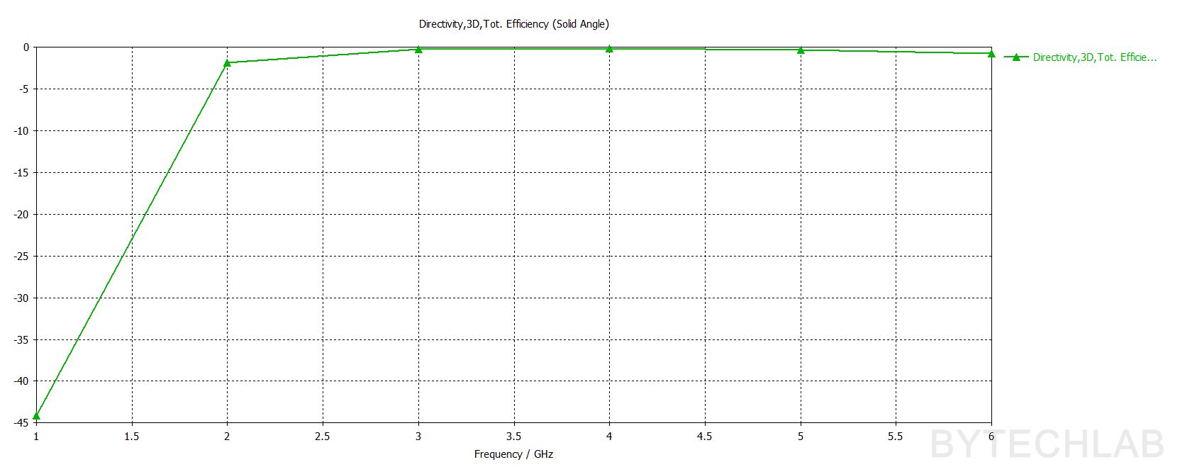
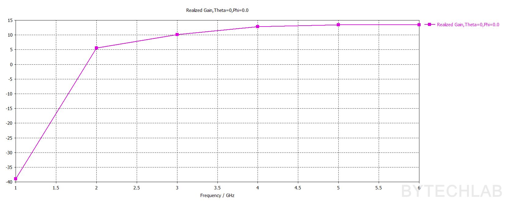
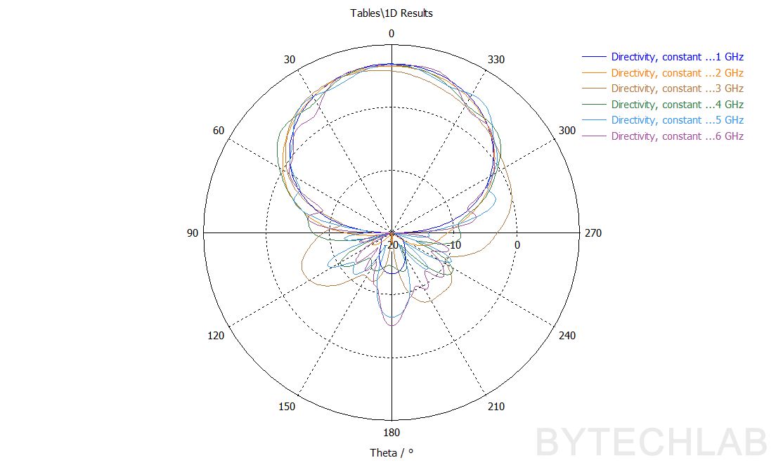
Below you can see also other antenna characteristics such as: Directivity -2D farfield cuts (phi=0,phi=90), |S11|, Port impedance, Directivity Max., Angular width (phi=0), Side lobe level (Phi =0), Total Efficiency, Realized Gain (phi =0, theta=0).
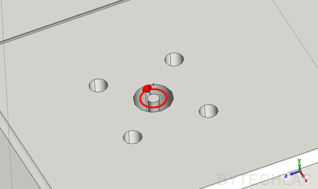
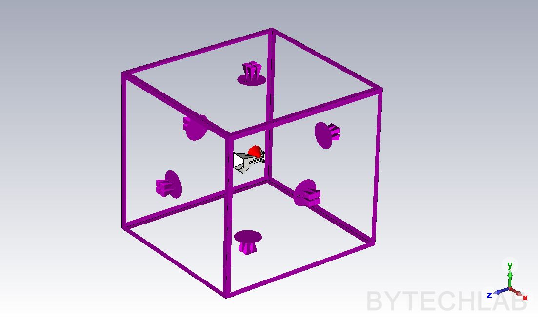
Also on the screens below you can see the port placement and the open boundary box around the antenna:
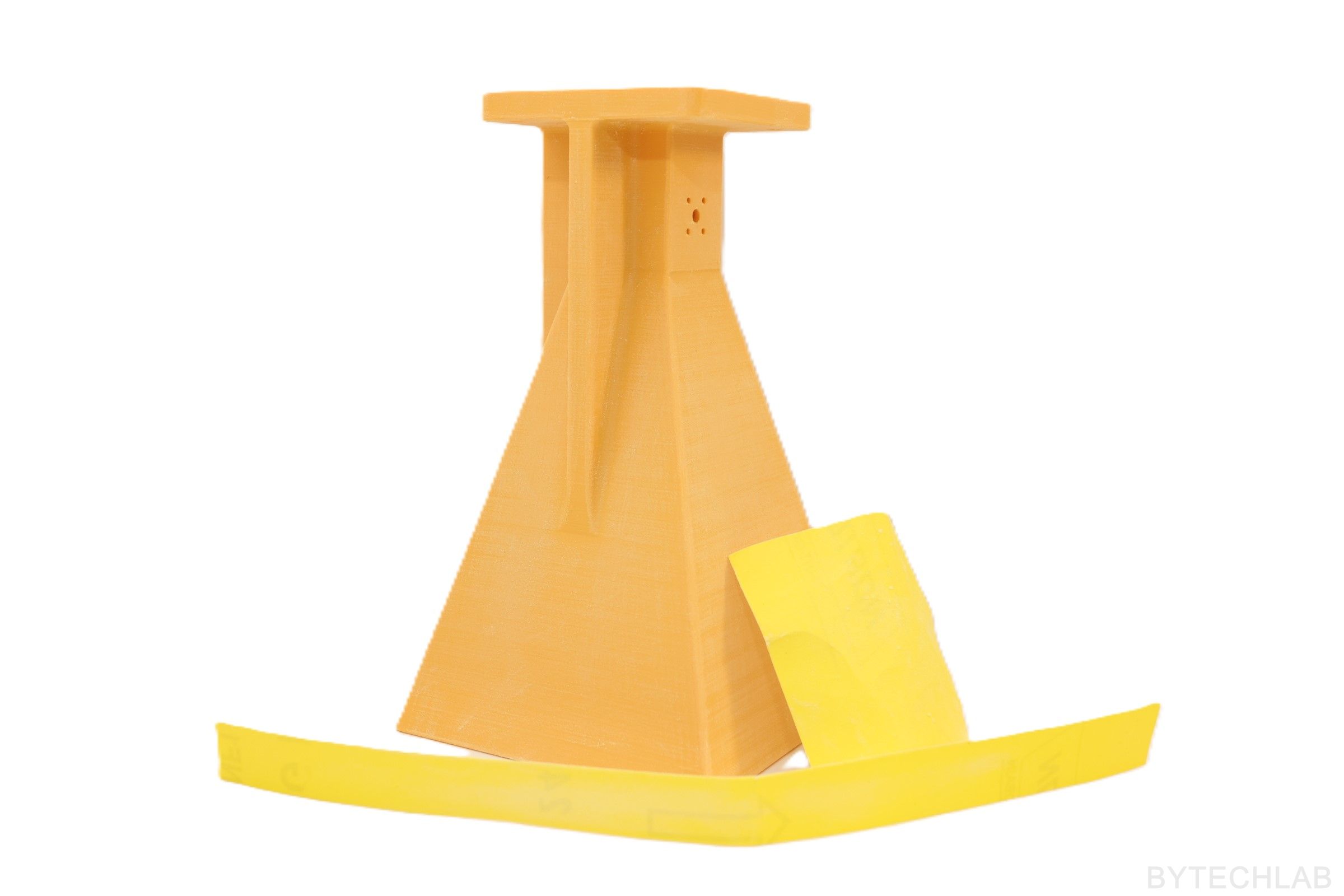
5) Manufacturing – 3D printing
Antennas were printed on BambuLab X1C with ABS filament. I have chosen ABS instead of PLA because it is easier to sand it, it has better heat resistance and it can be smoothed with acetone. On the video above you can see the printing process of one of the antenna halves.
Recommended printing settings:
- 0.12 mm layer height,
- ABS filament,
- 90 % rectilinear infill,
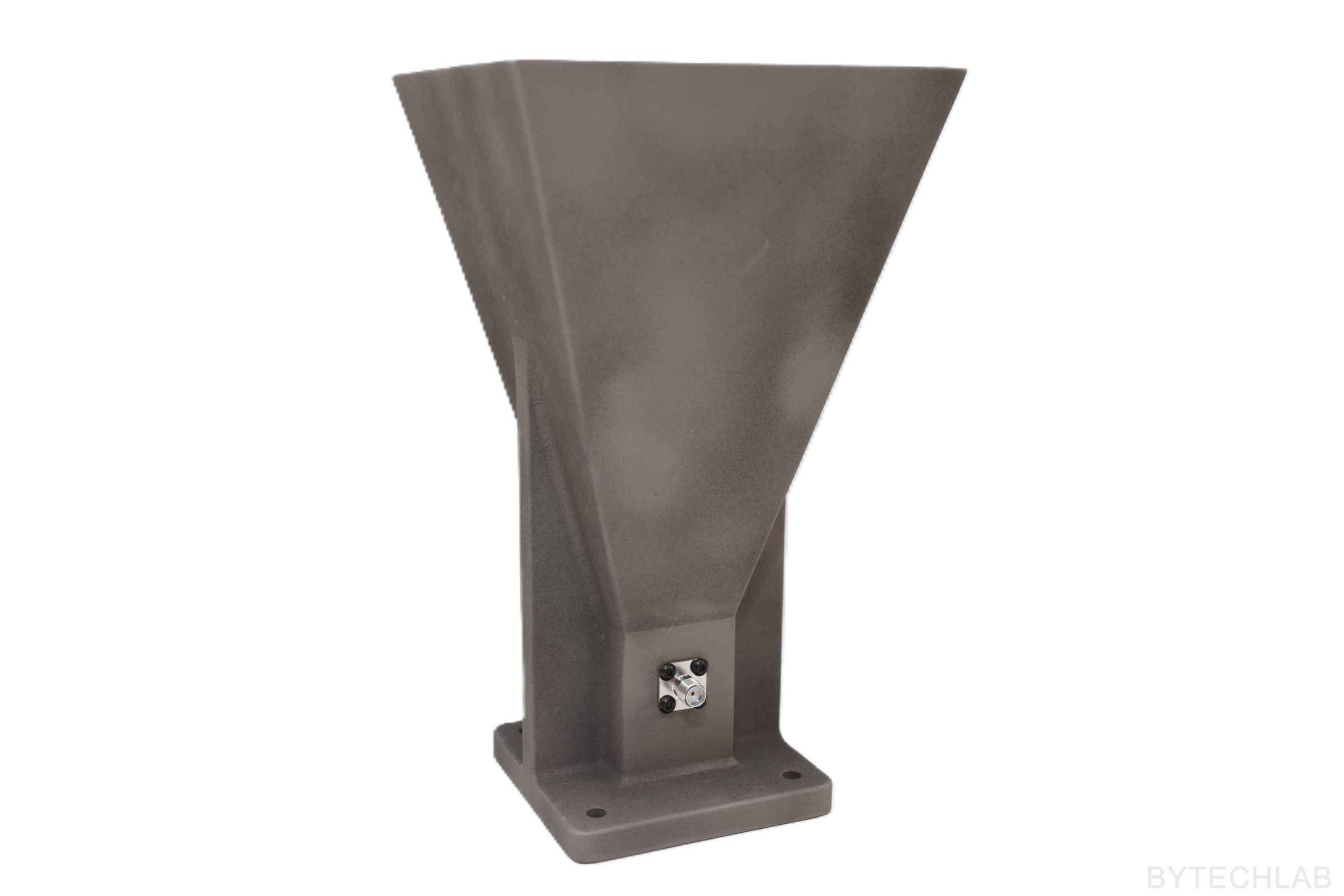
6) Coating with conductive paint
After sanding the antenna halves and cleaning all of the surfaces I have applied two coats of MG CHEMICALS 843AR silver coated copper conductive paint. It has very good resistivity of 2.2 * 10-4 Ohm * cm. Unfortunately this paint is quite expensive ( about 80 USD per can). But is worth the money because you don’t have to do anything else with this coating – copper plating is not needed.
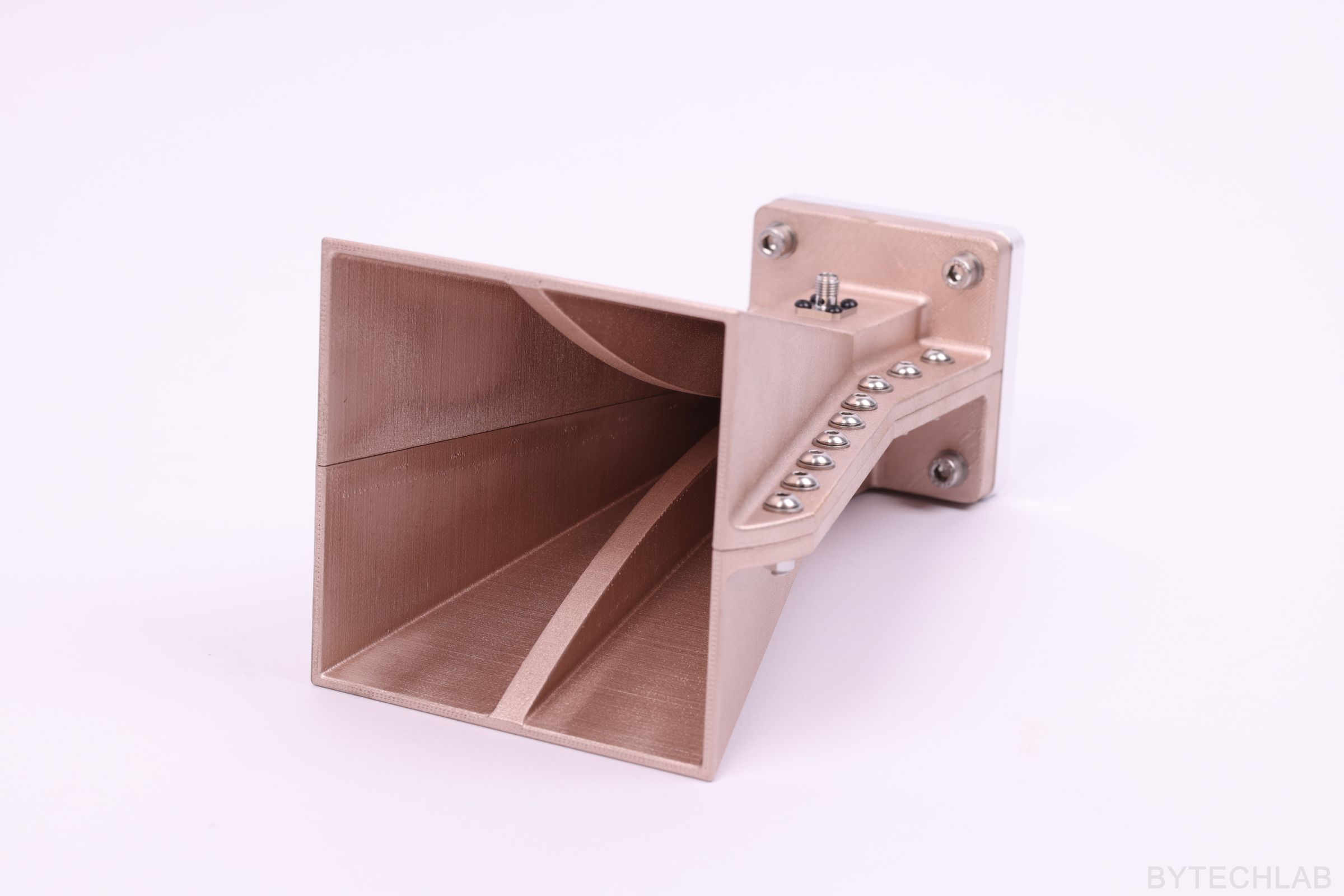
7) Assembly
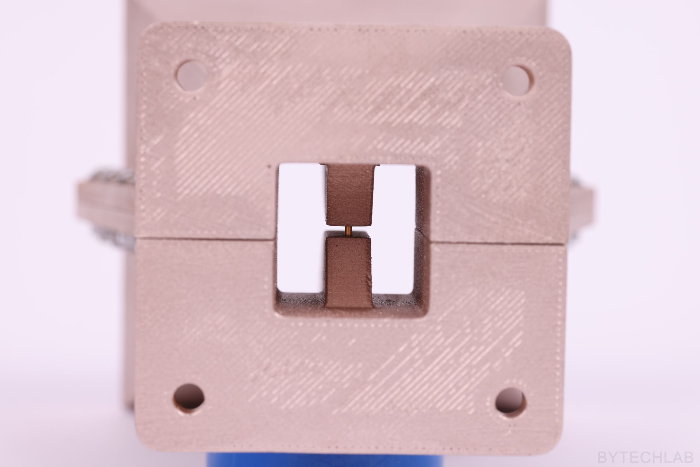
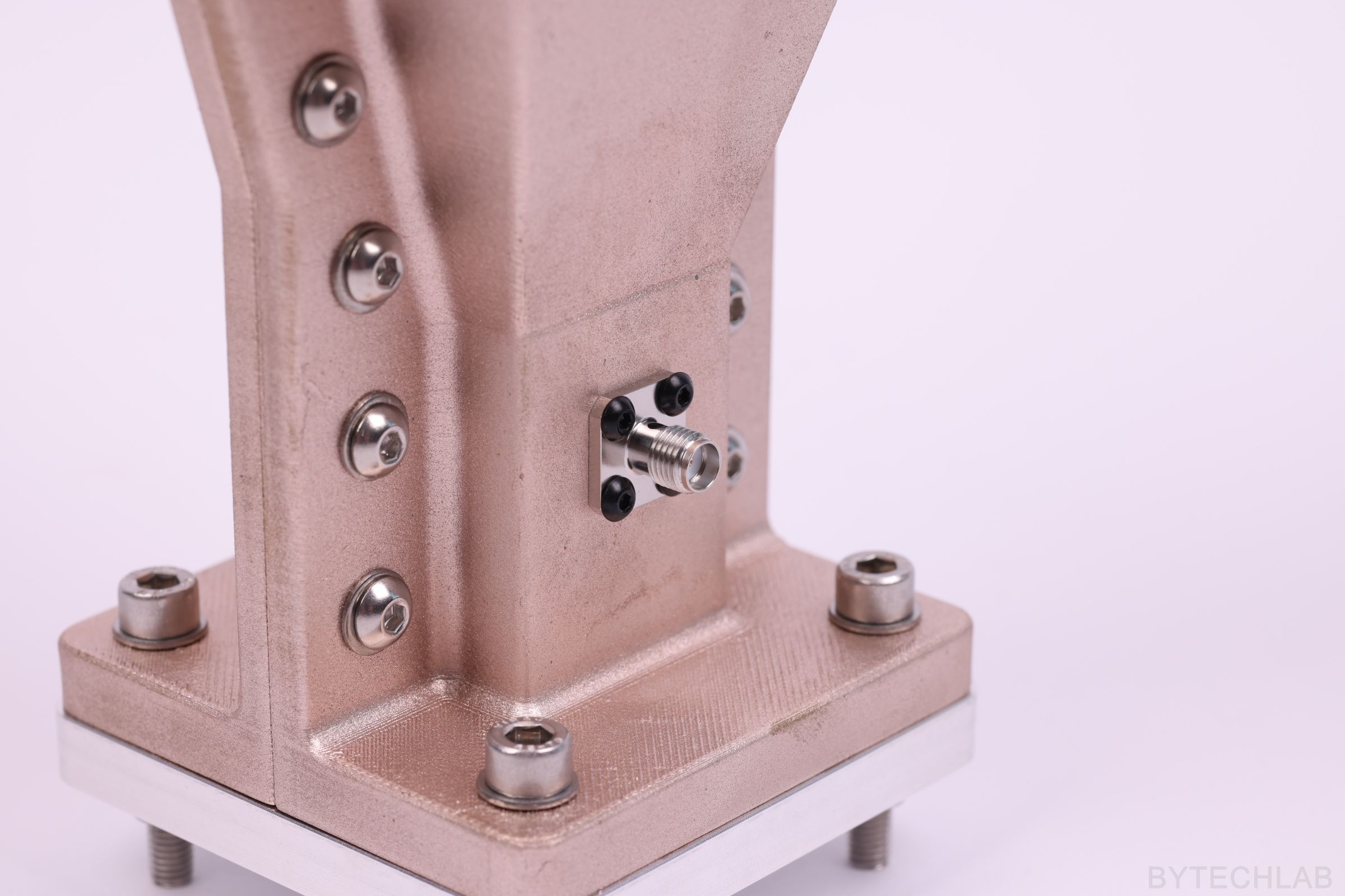
After painting I have mounted the Amphenol 2950-6061 SMA connector to one of the halves with use of M2.5 self tapping screws. To connect electrically the feed pin to the second halve I have added a drop of conductive paint on top of it. After assembling both halves together I have quickly added the screws on both sides to ensure that the feed pin won’t move when the paint is curing.
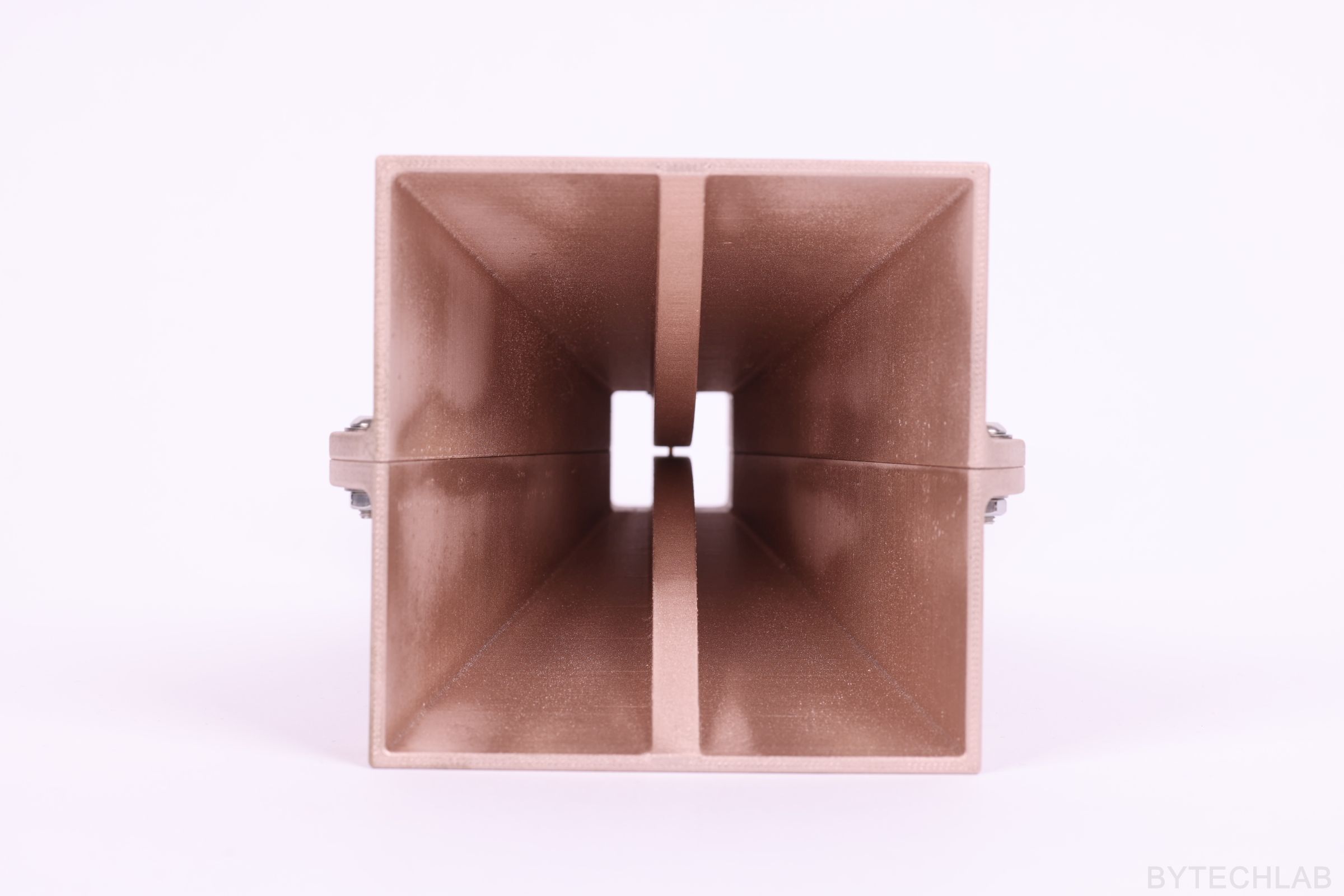
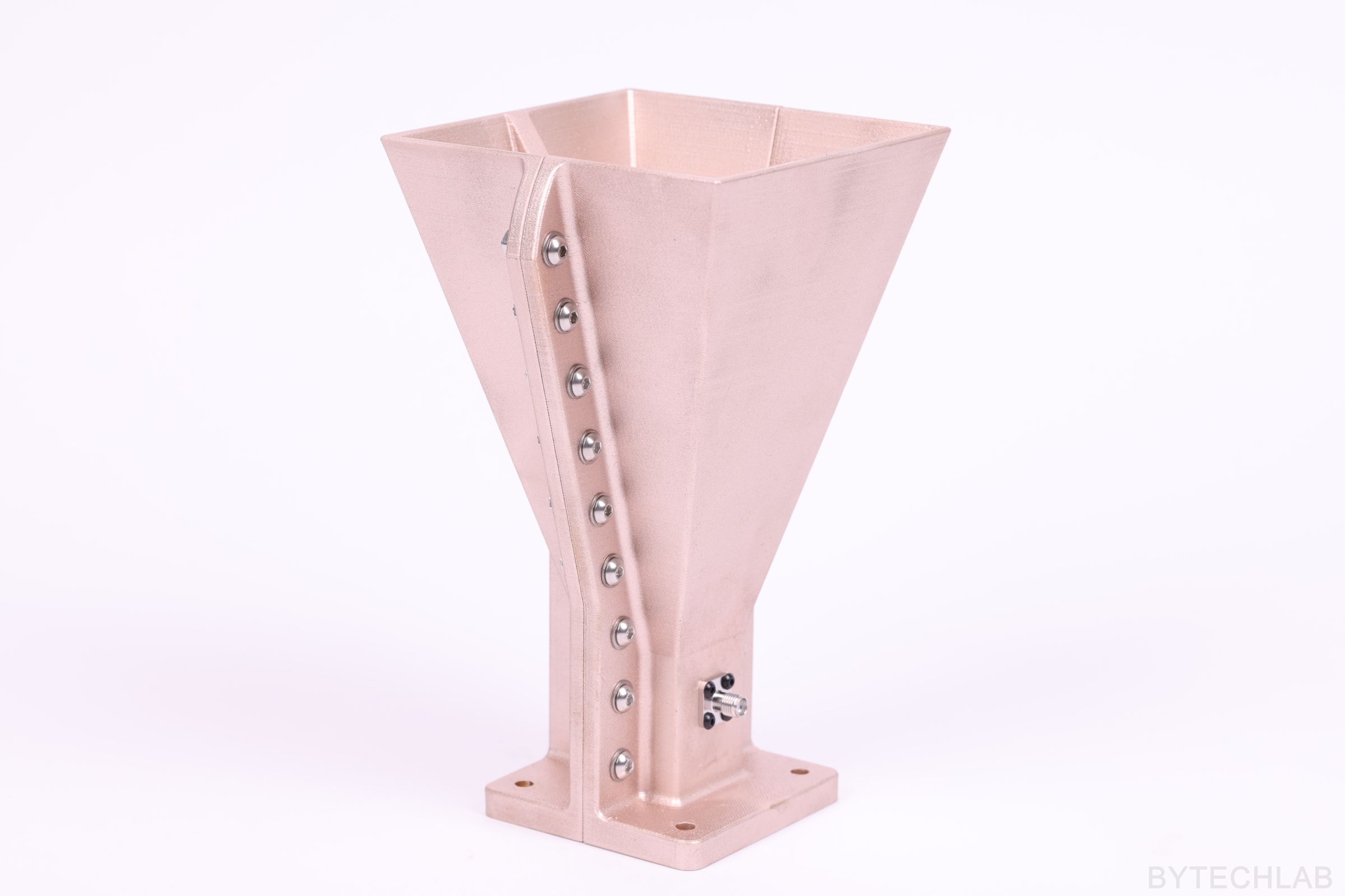
As a last step I have mounted the Aluminium CNC milled backplate to both close the waveguide and stiffen the whole antenna.
8) Testing
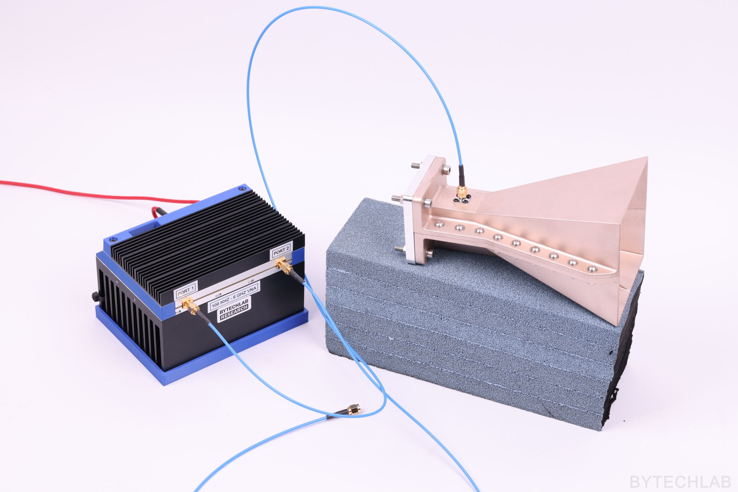
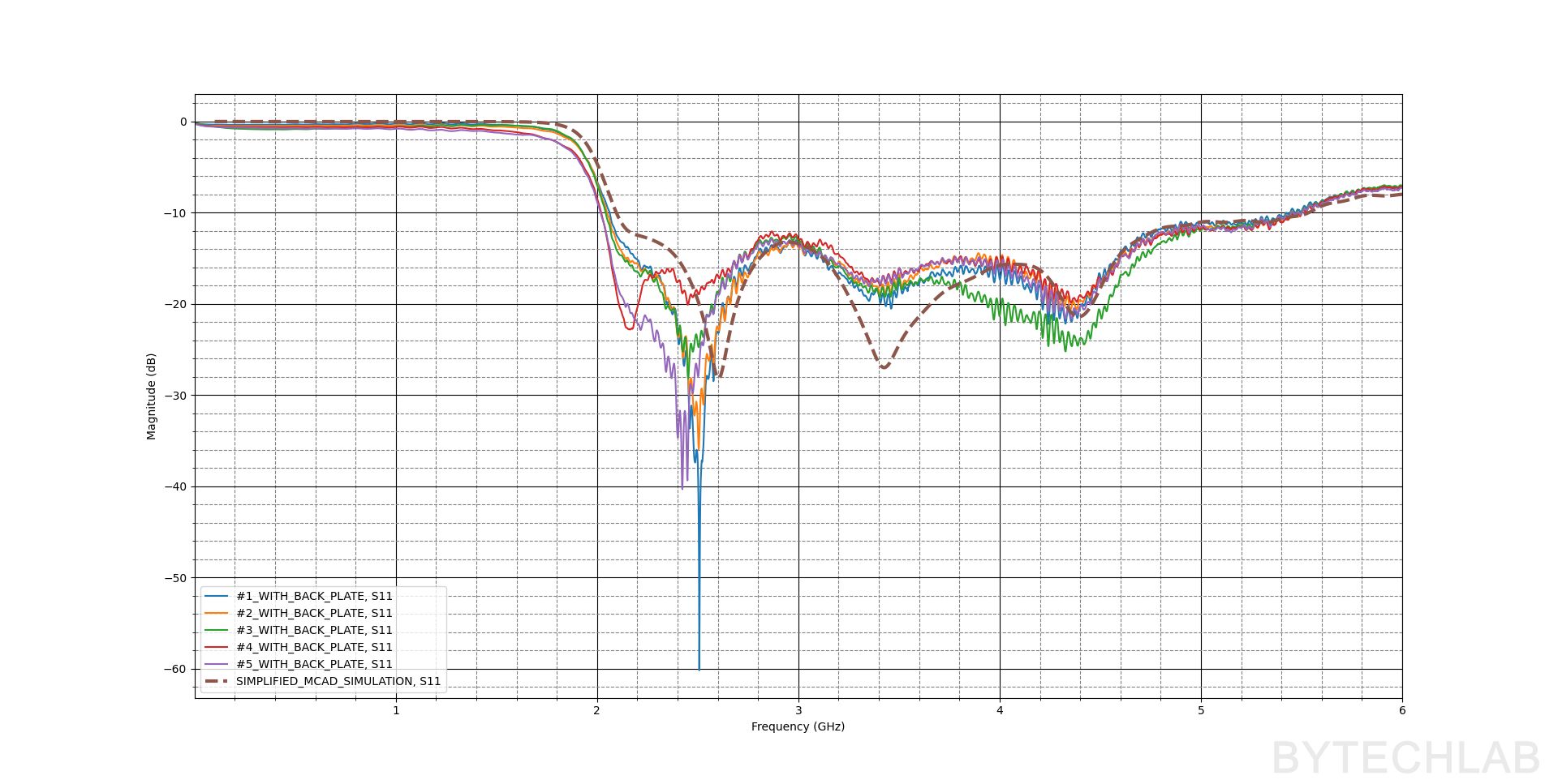
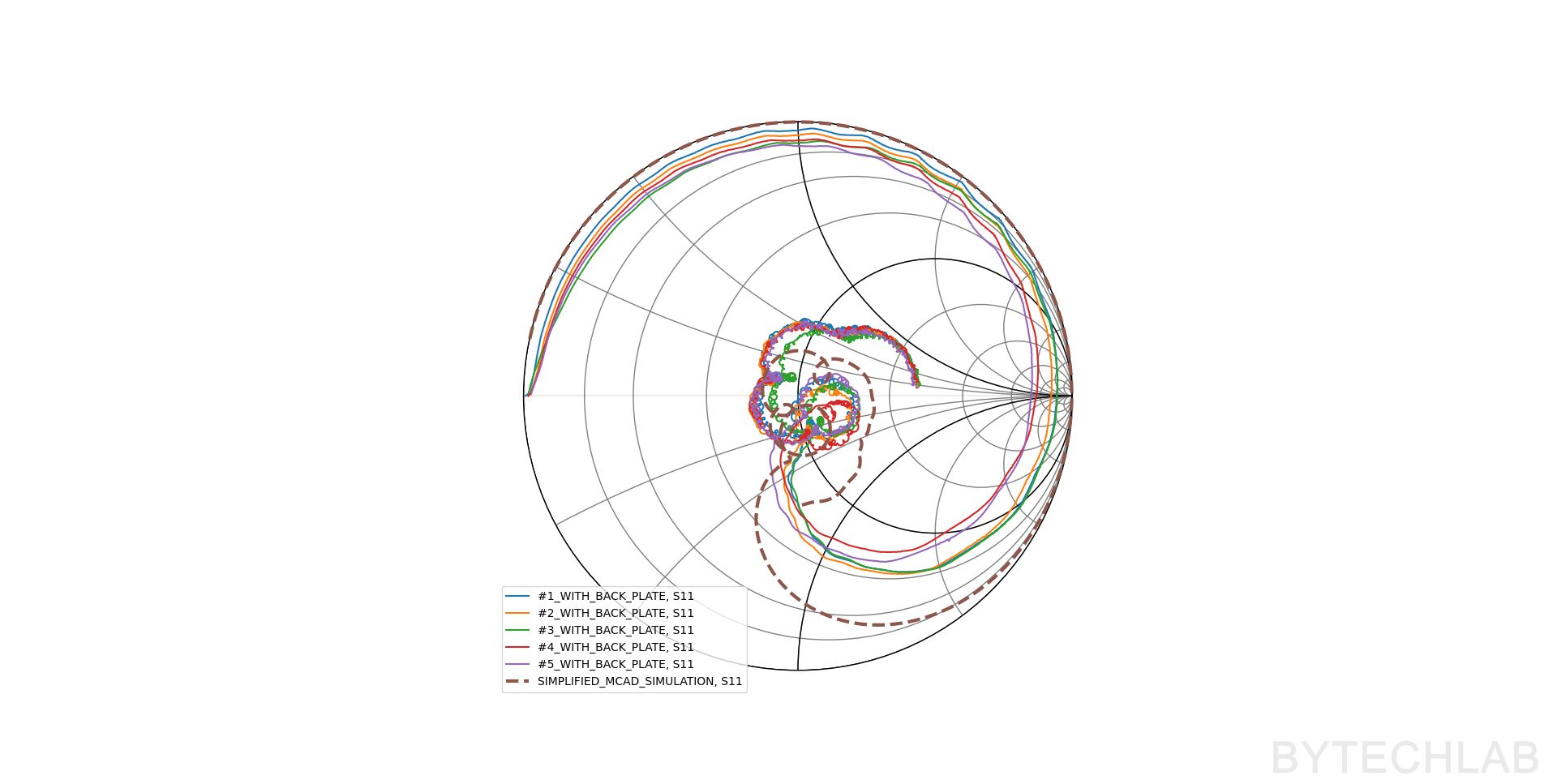
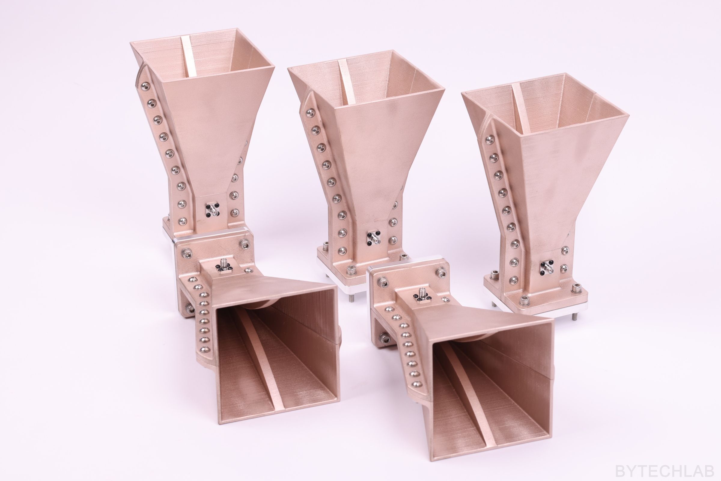
As a final step I have measured 5 antennas that I have made to check if they are all working as intended. For this purpose I have used my 6 GHz VNA. Please note that this measurement was not performed in anechoic chamber or free space – there might be some measurement artifacts due to this.
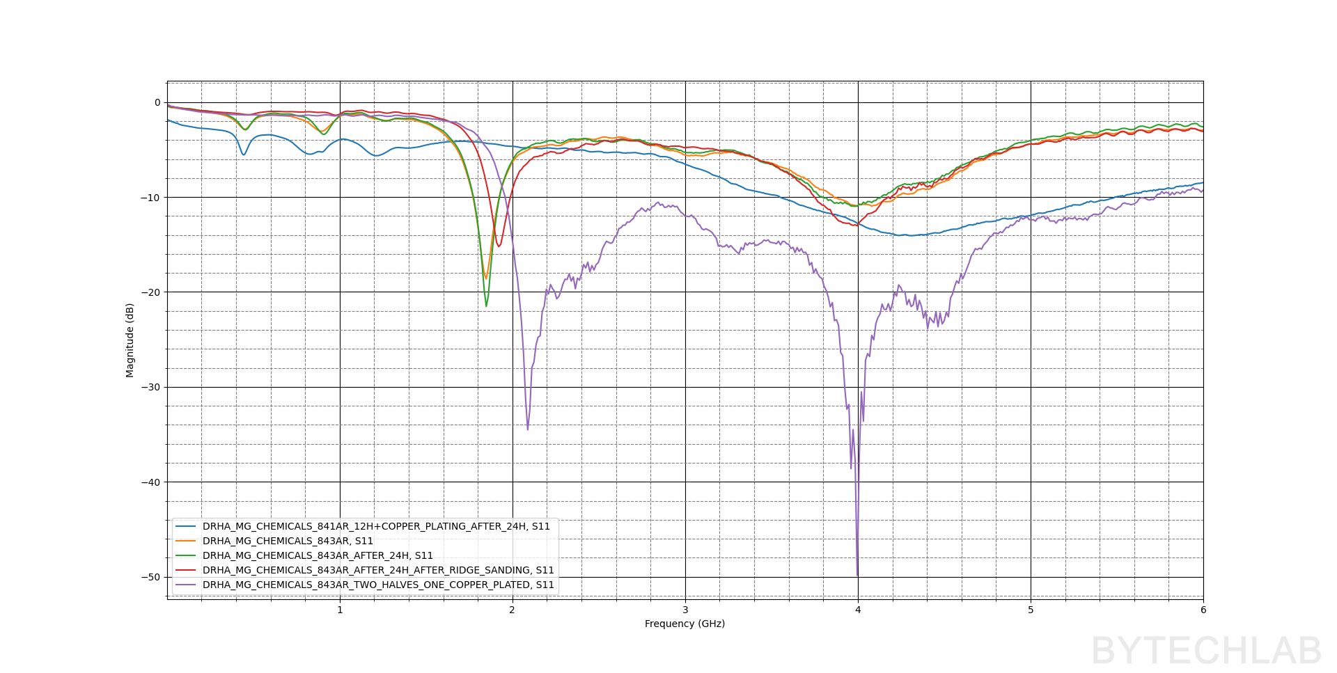
On the chart below I have plotted both simulated and measured |S11|. The measurement quite closely correlates with the simulation. There is some variation between antennas due to manufacturing tolerances – It’s quite hard to get accurate enough dimensions from FDM 3D printer, It’s also hard to get accurate coating thickness when hand painting.
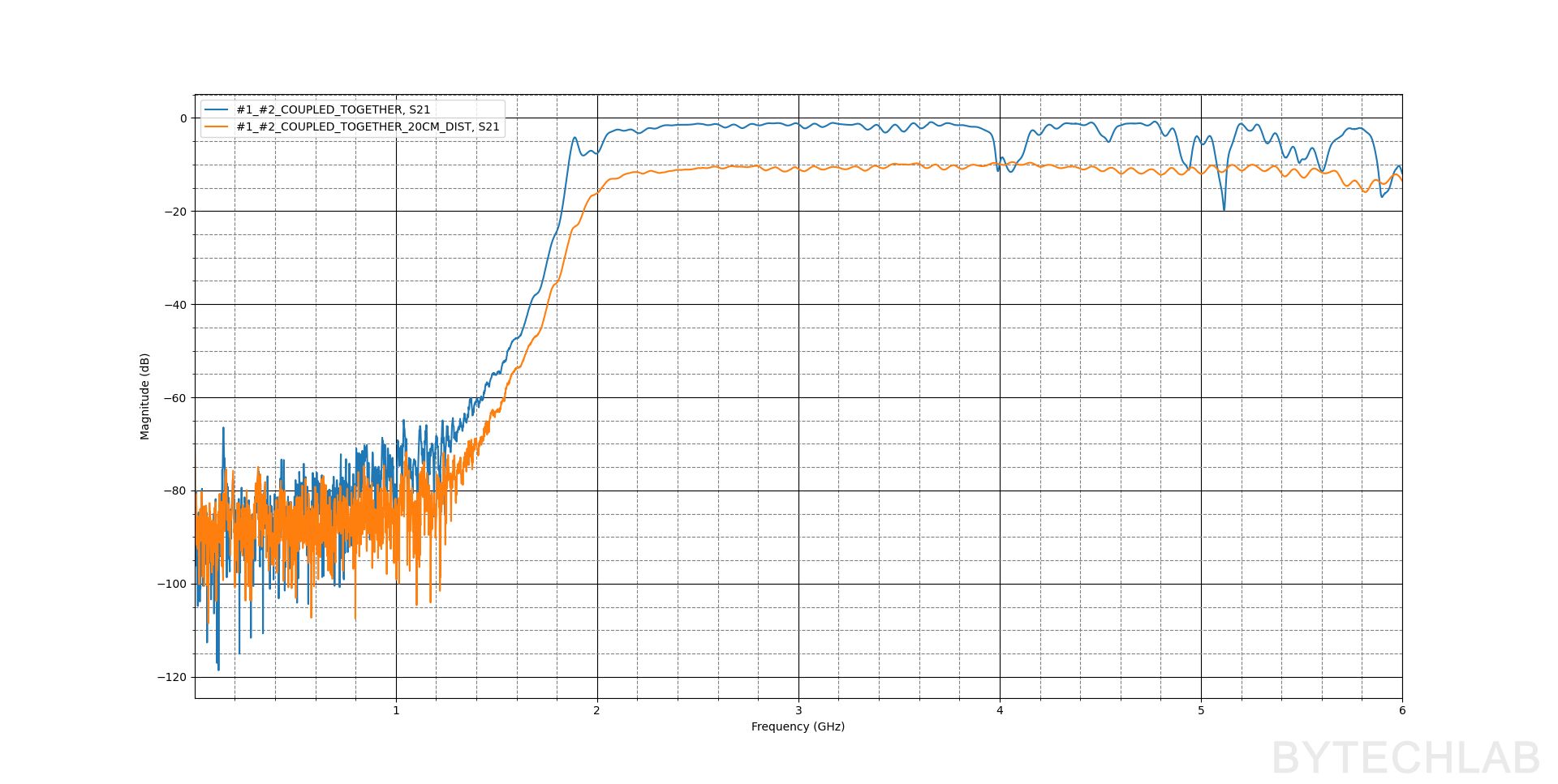
To test the antennas even more I have measured |S21| of two antennas that are pointing to each other at two distances (d=0cm and d=20cm).
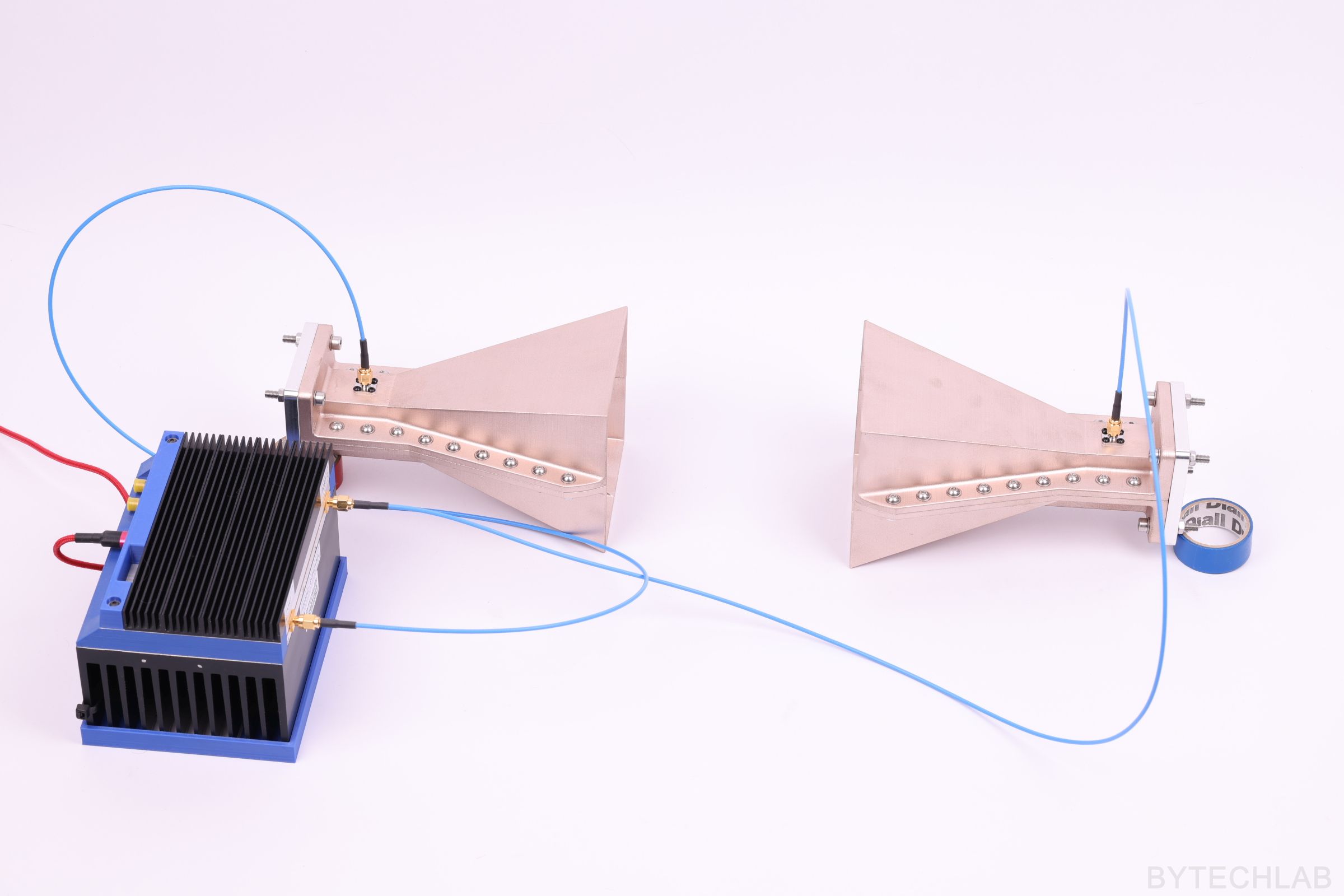
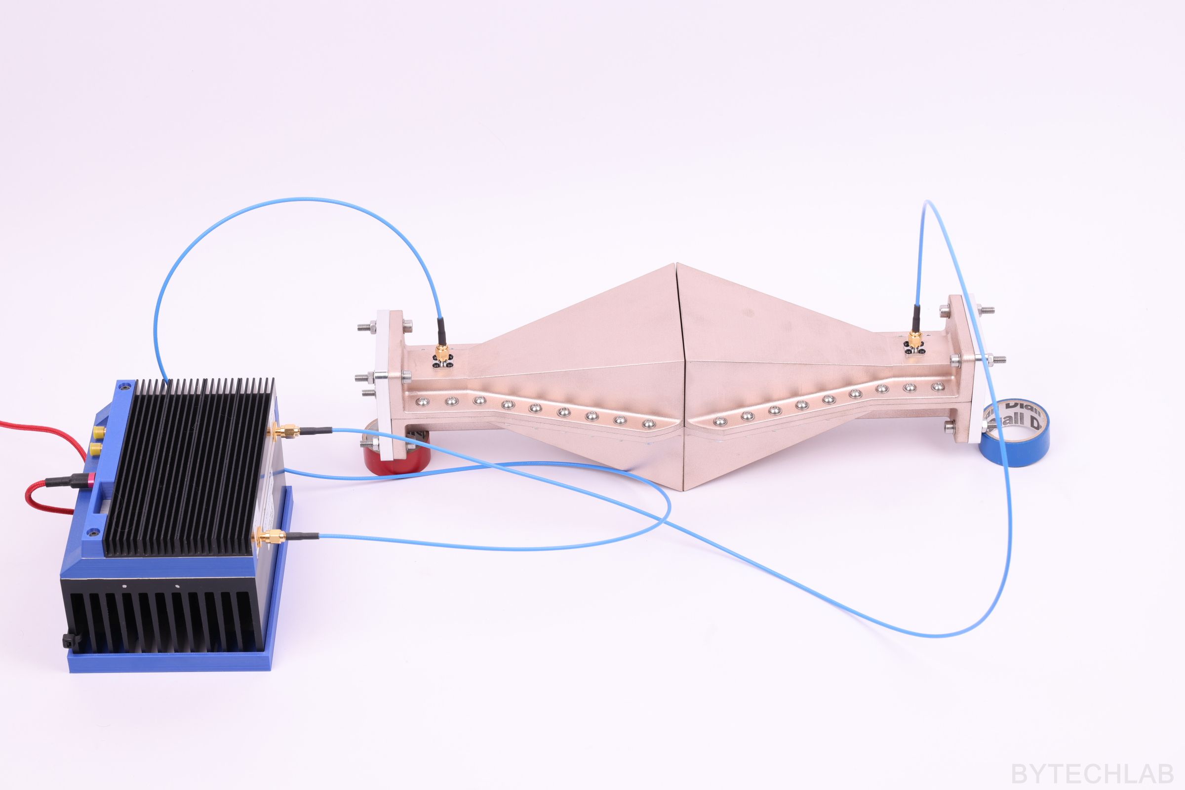
At d=0cm there are some notches probably due to some kind of resonances. But from this measurement I can estimate that the antenna efficiency is very high. |S21| = -1.5 dB for both antennas, so there’s about -0.75 dB of loss per each antenna. Perhaps in reality this is even better because some waves/fields are leaking out through the sides that are not 100% sealed.
At d=20 cm the response in the whole operating band is very flat which is perfect!
As a last test / experiment I have made a video where I move my hand in front of the antenna while measuring the |S11|. You can see that the reflection vs. frequency is changing when I move my hand.
Antenna radiation patterns measurements coming soon!
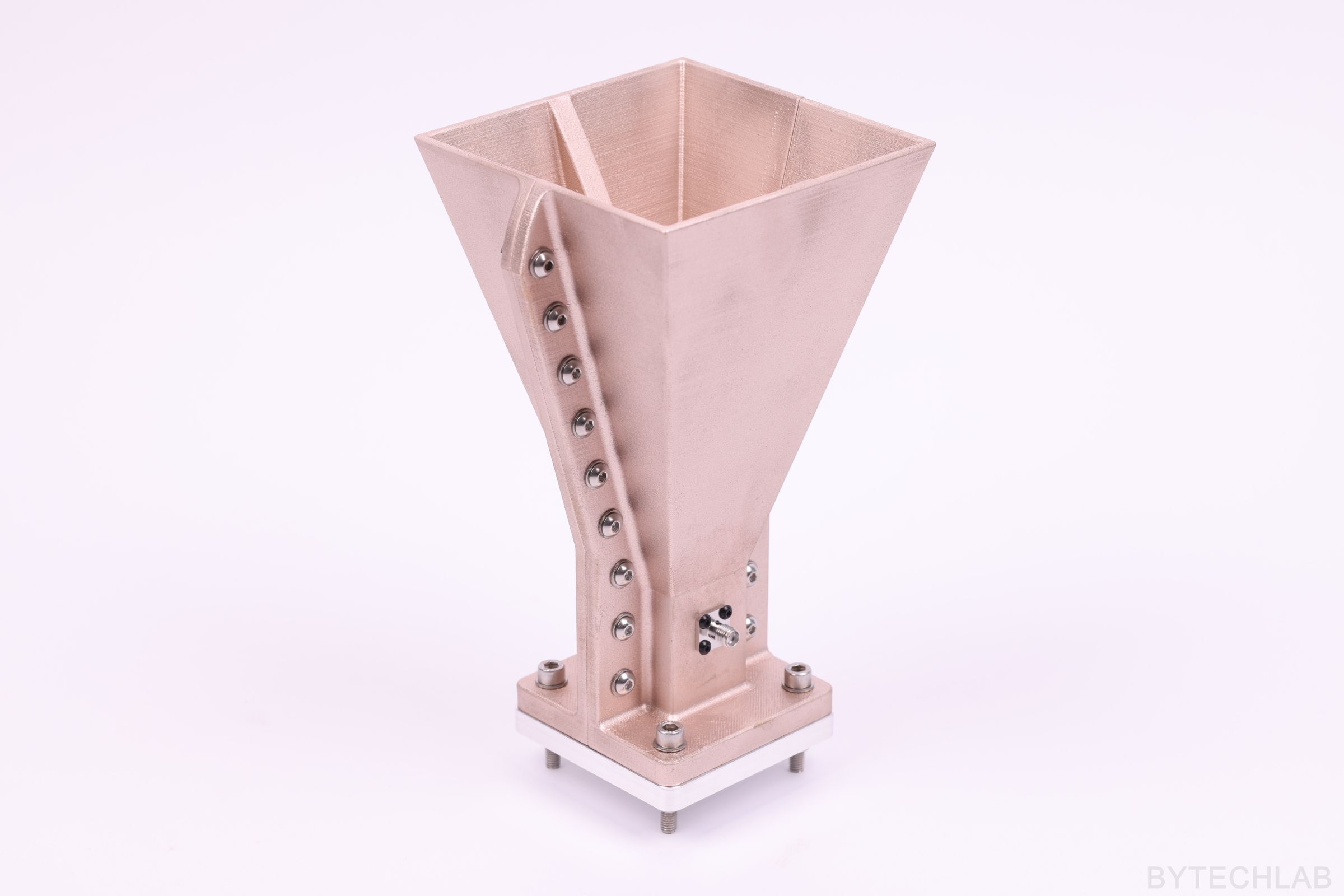
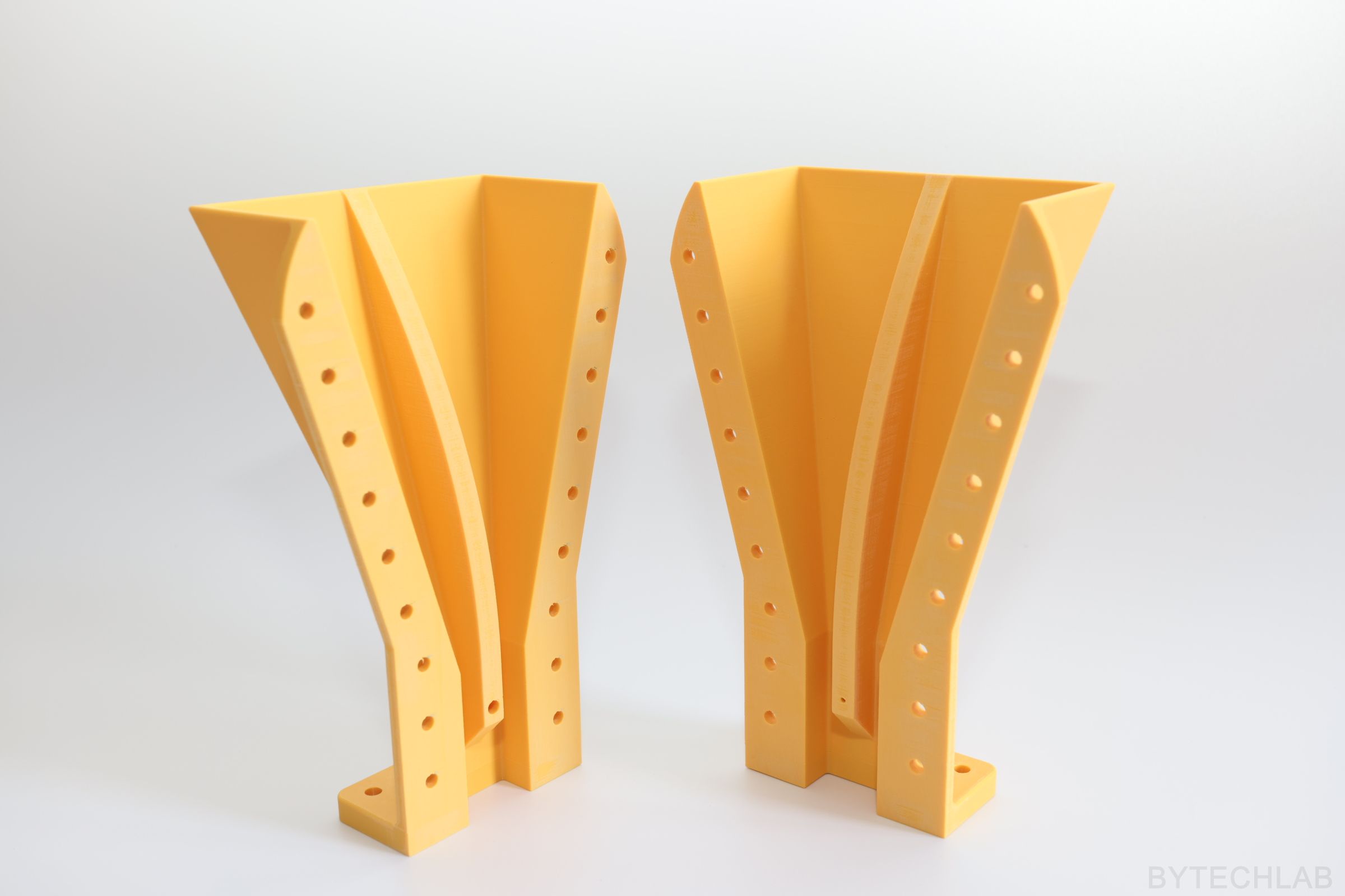
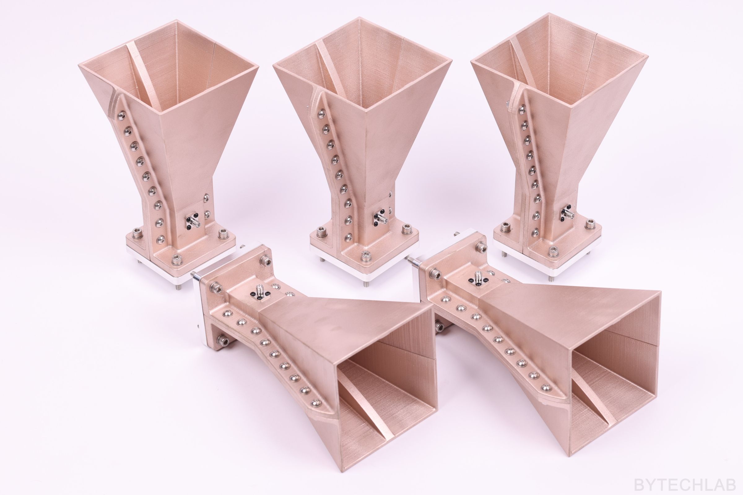
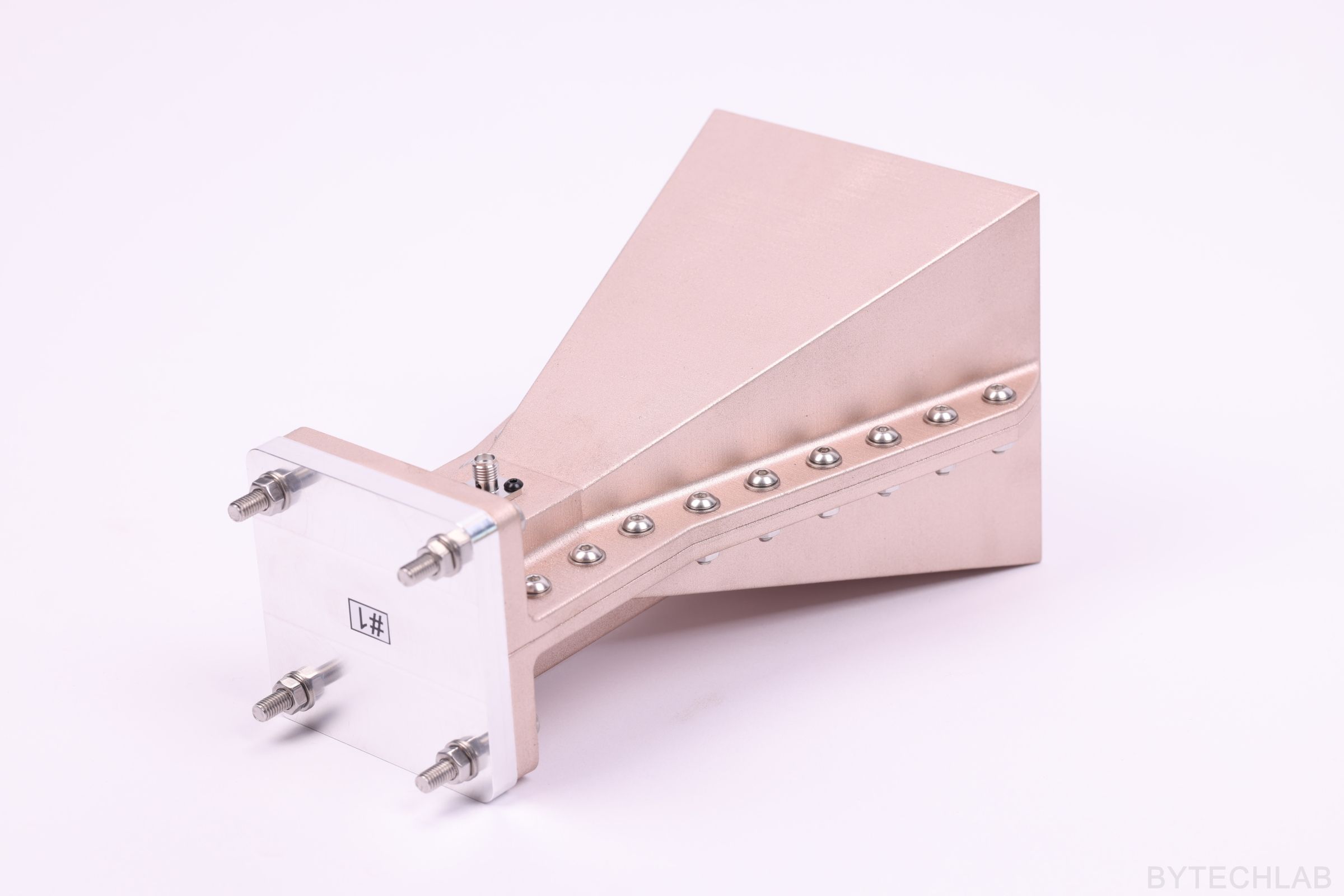
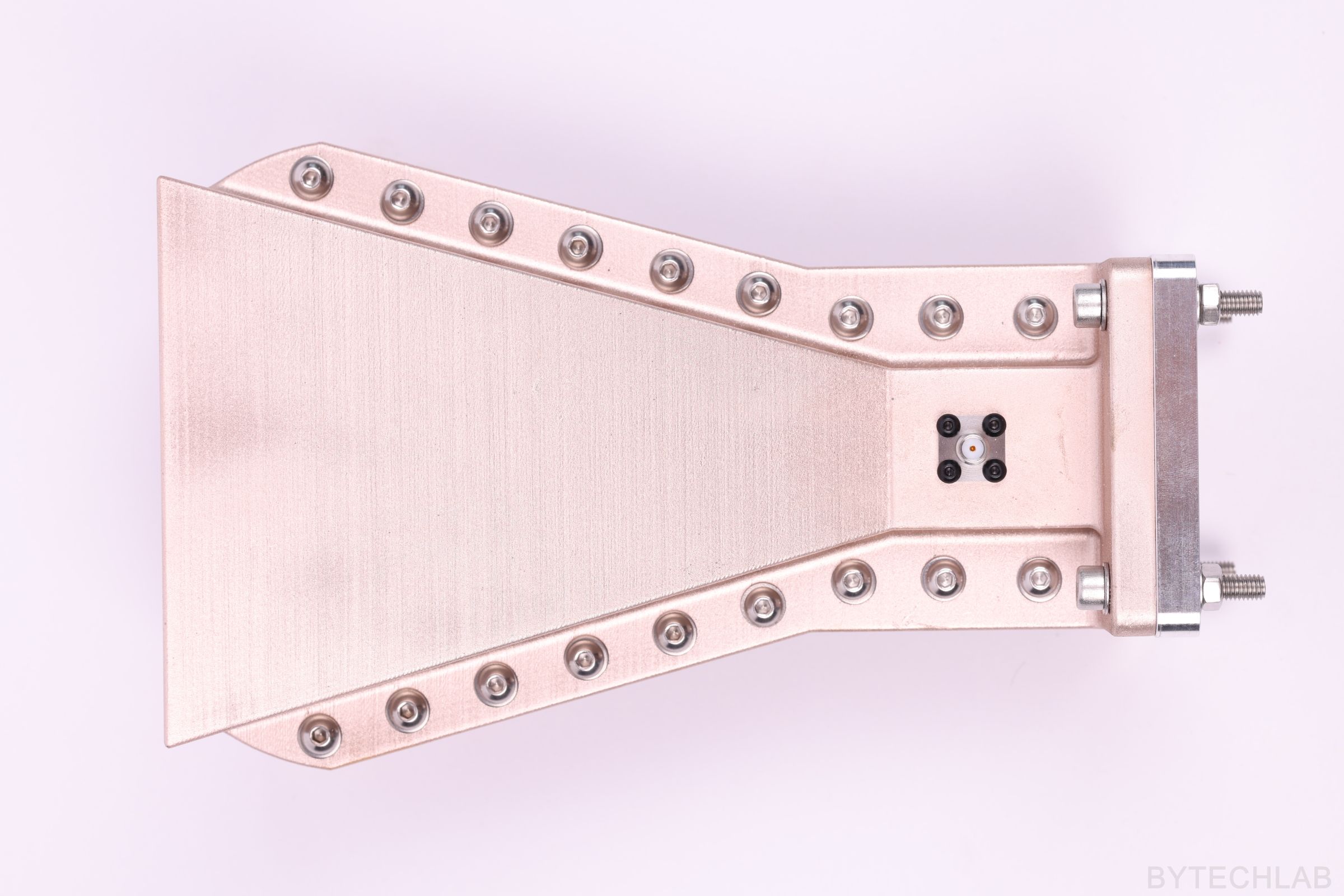
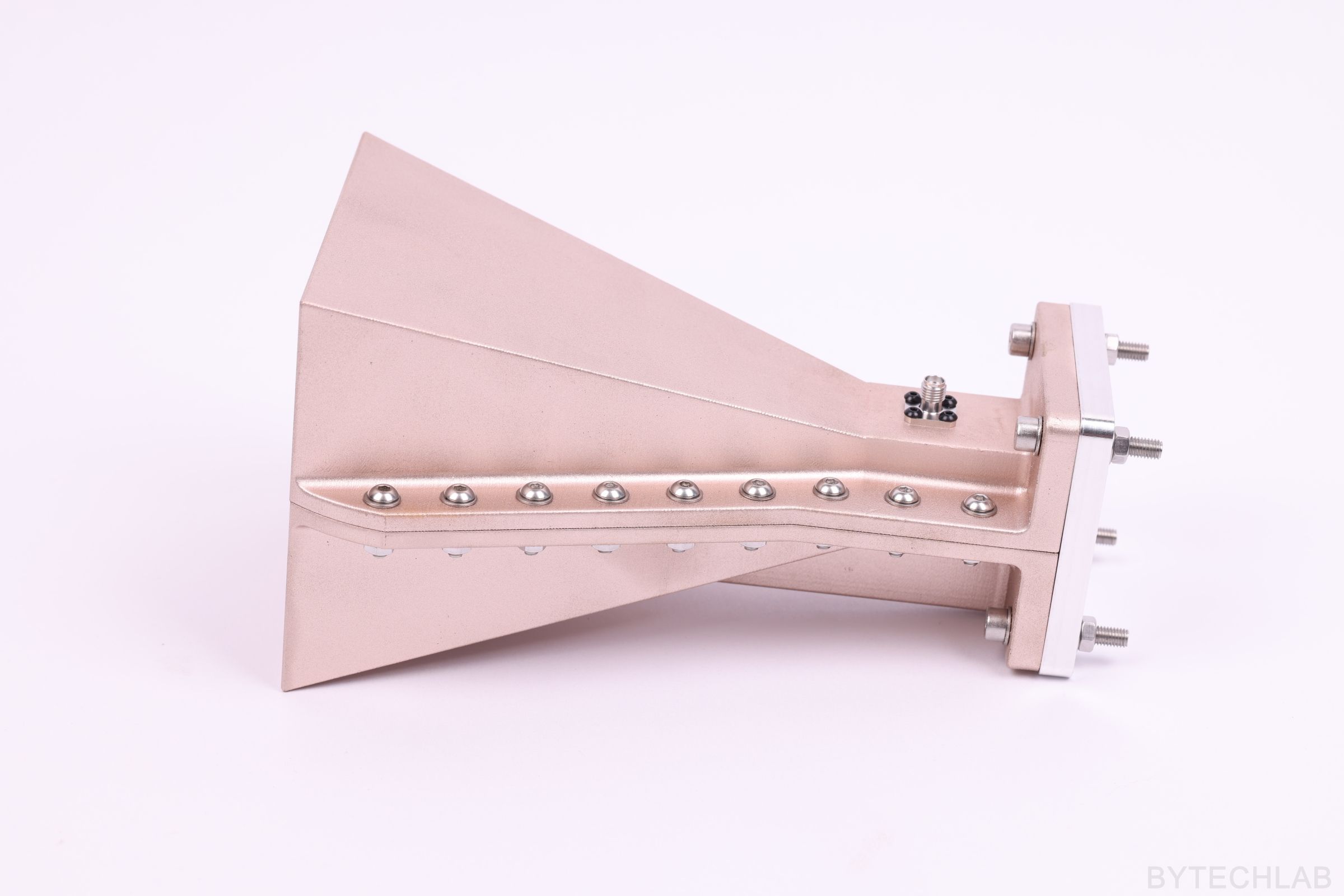
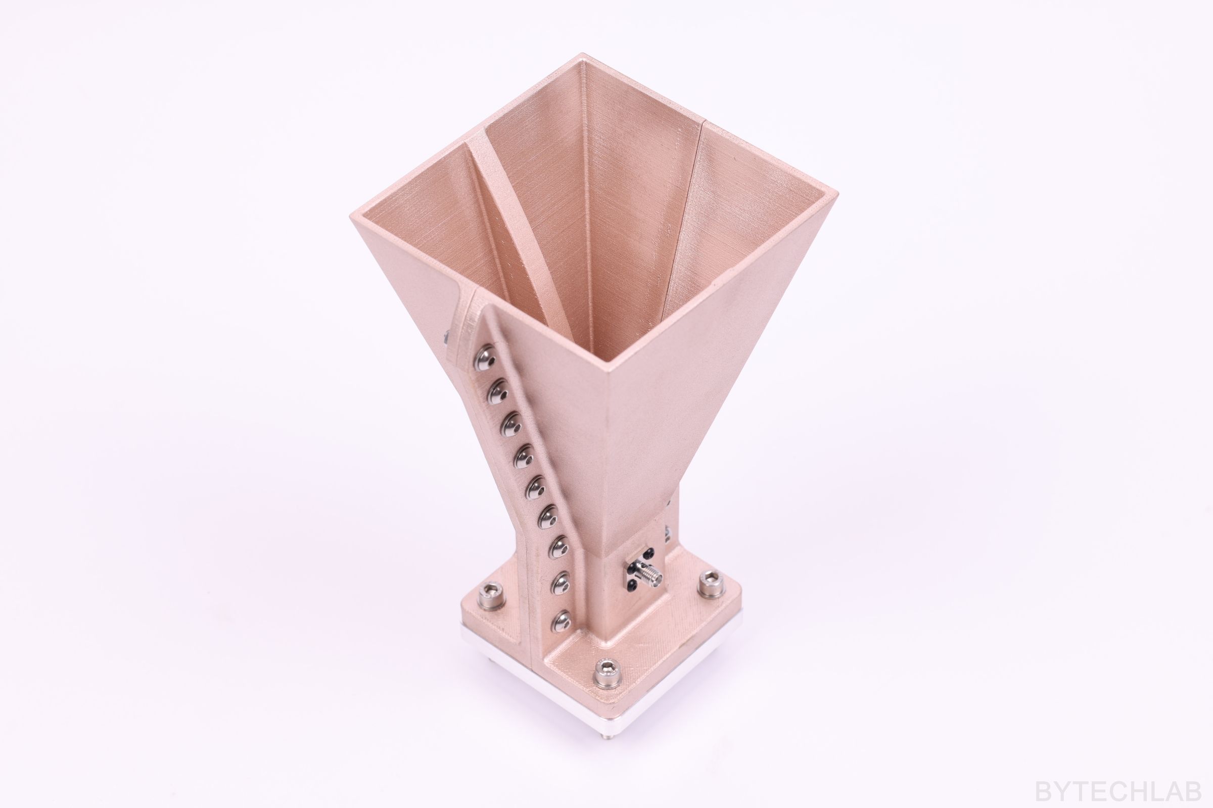
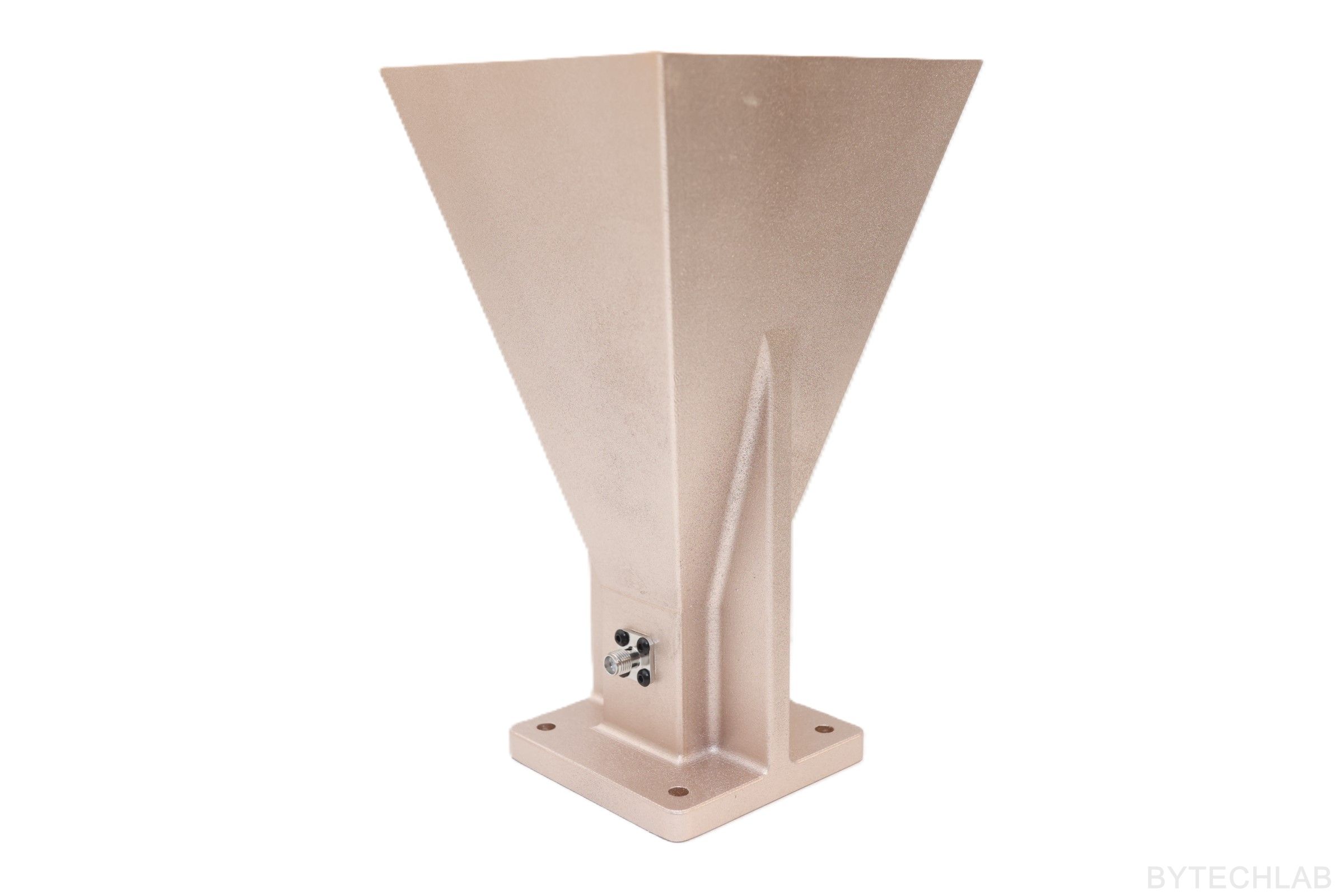
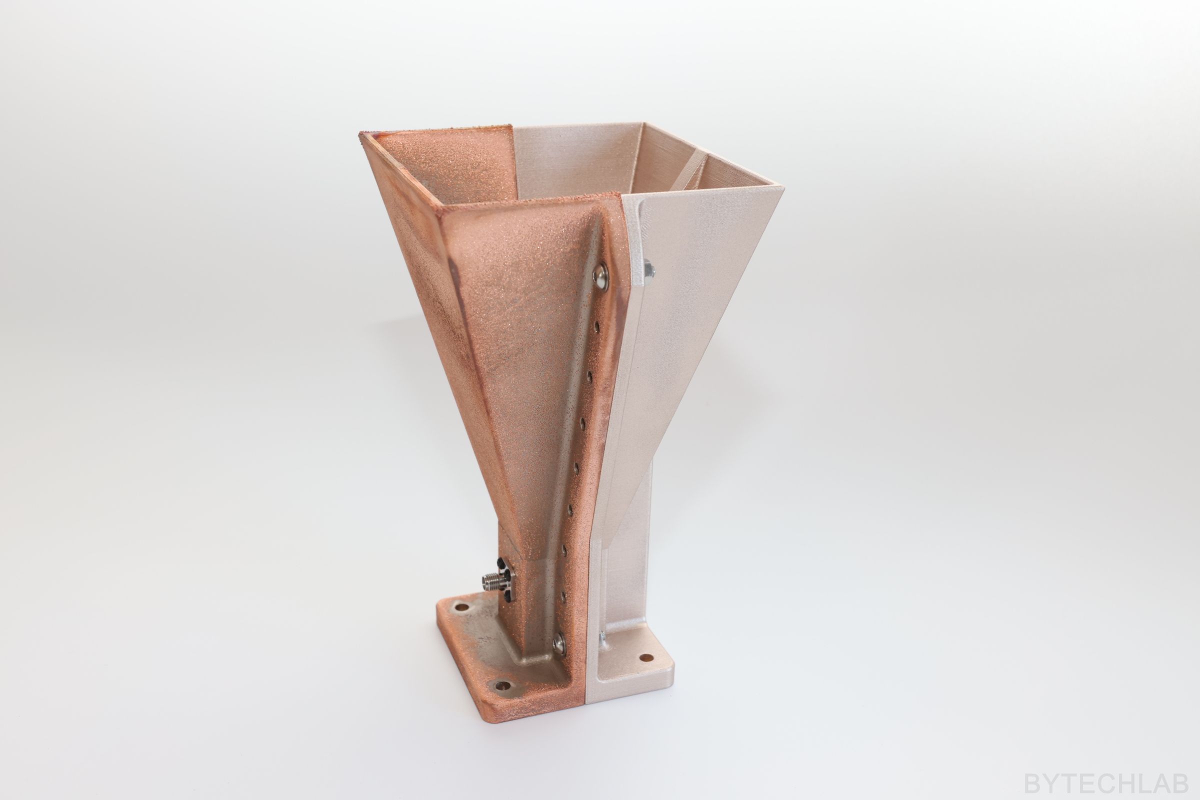
9) Final version – more photos
10) What went wrong during the prototyping process ?
Getting to this point wasn’t easy, I had to make 3 prototypes before it actually started working correctly. Below I will try to describe all of the mistakes that I have made.
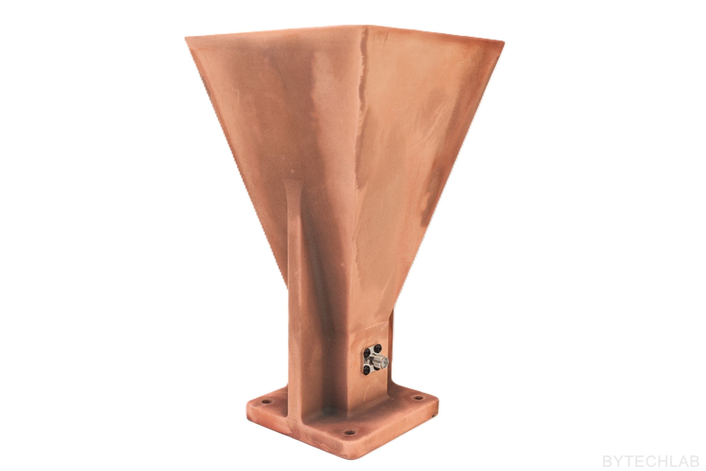
10.1) Coating with MG CHEMICALS 841AR & Copper plating
Coating with a MG CHEMICALS 841AR nickel conductive paint was a huge mistake. This paint has way too high resistance. The antenna wasn’t working at all. It behaved more like a attenuator or 50 Ohm load. I tried to copper plate it to fix it but I wasn’t able to get good enough copper plating quality to fix it.
10.2) Surface finish ( Sanding & Acetone )
At these frequency the surface finish plays important role – the smoother the antenna and the conductive paint coating is the better it will work.
10.3) Ridge surface quality & metal plating on the ridges
As it turned out the most important part of the antenna is the ridge surface. It has to be very smooth and coated with conductive paint very evenly. It was impossible to accomplish this with the V1 of MCAD design (antenna printed in one piece). Because of this I have splitted the antenna into two halves that are later assembled together with use of screws (MCAD V2). Old one piece design even with better paint (MG CHEMICALS 843AR) didn’t work well.
10.4) Path between inner surface and outer surface
Splitting the antenna into two halves has another benefit – the outer and inner antenna surface connect to each other from 4 sides instead from only two in one piece design. This is very important because the two halve design reduces the impedance from the inner surface to the SMA connector shield placed on the outer surface of the antenna (the paint is not as conductive as solid metal)
Above you can see the third prototype that actually worked quite well – you can see this on the |S11| chart above (DRHA_MG_CHEMICALS_843AR_TWO_HALVES_ONE_COPPER_PLATED).
11) Does it work above 6 GHz?
Recently I have received lots of questions about the performance of this antenna above 6 GHz. This antenna wasn’t initially simulated or designed for these frequencies, so I dont expect much from it. I have performed additional simualtions up 12 GHz to answer these questions.
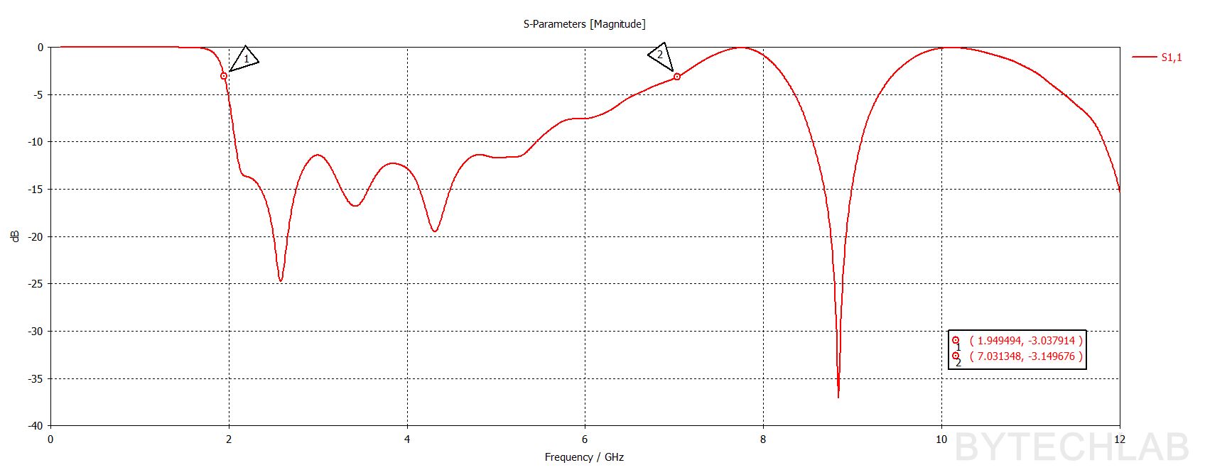
From |S11| perpective it looks like the operating bandwidth of this antenna is actually a little bit higher than 6 GHz (1.95 – 7 GHz [-3dB] ). Unfortunately as expected the impedance matching breaks above 7 GHz, so the antenna is not usable above 7 GHz. Let’s assume that the |S11| is not that bad above 7 GHz and let’s take a look at other antenna characteristics.
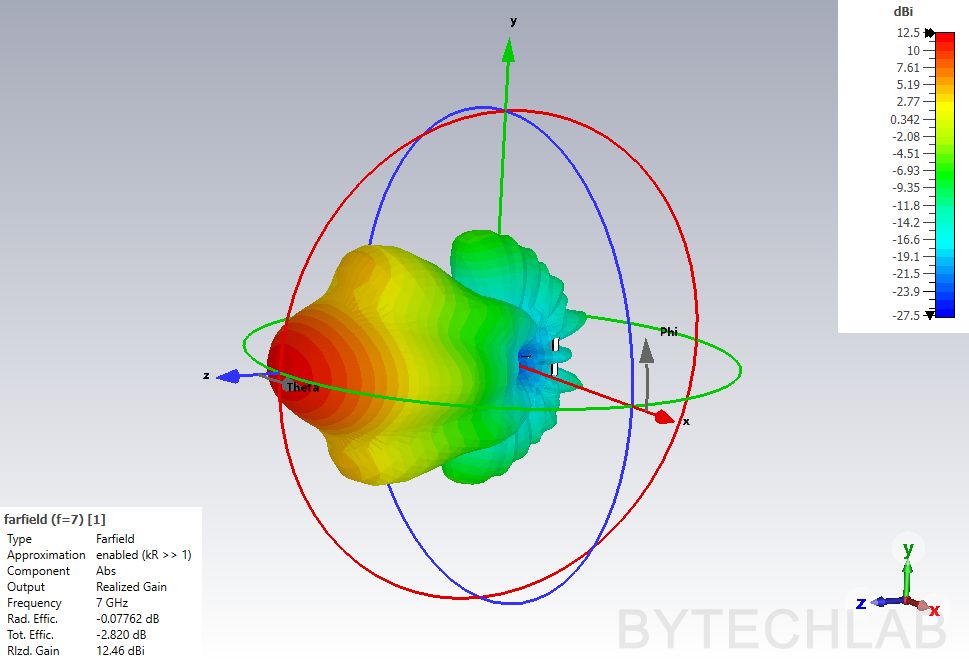
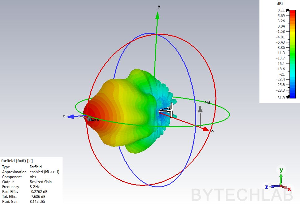
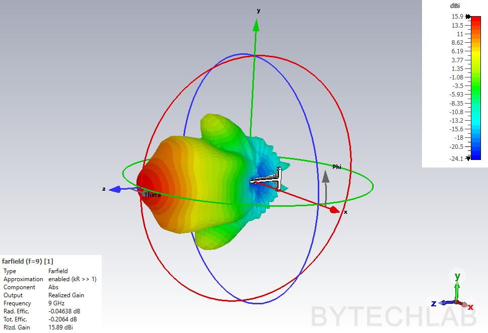
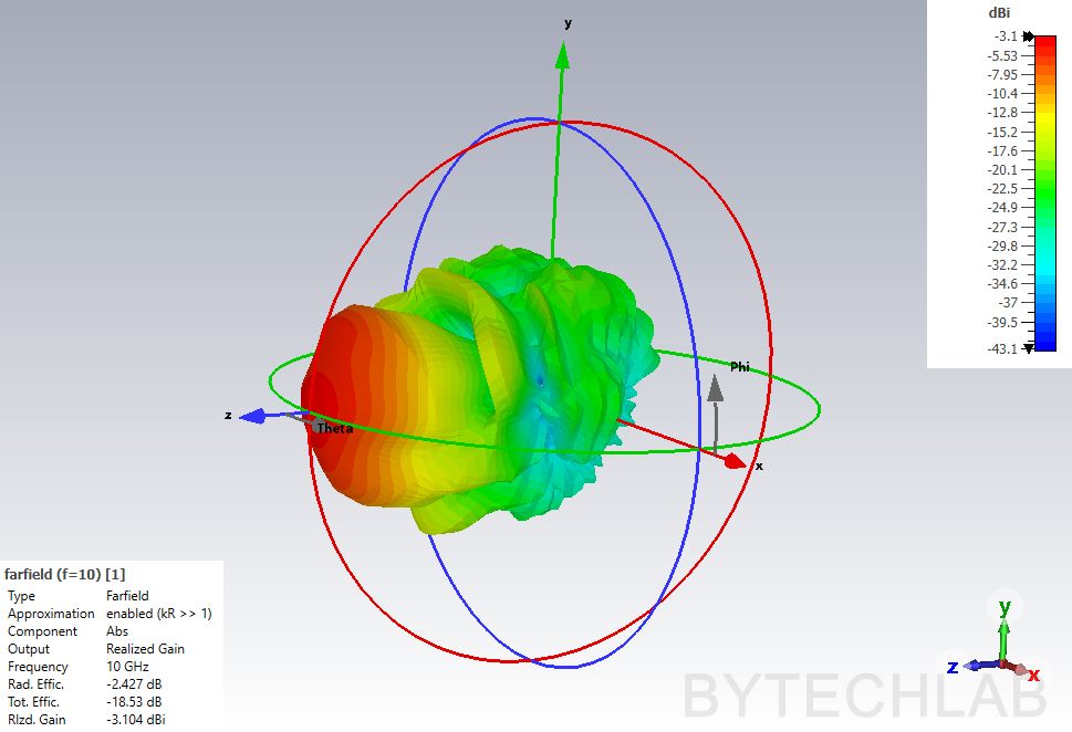
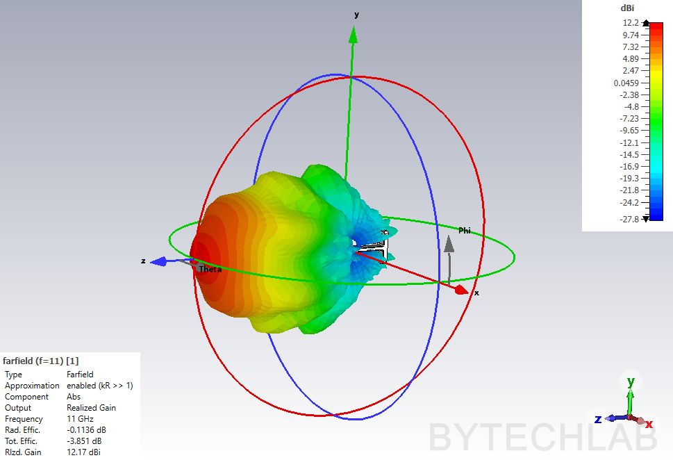
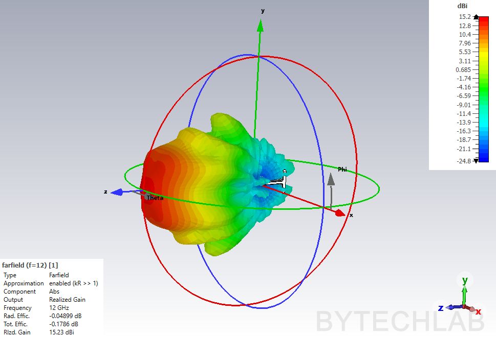
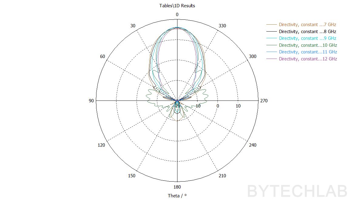
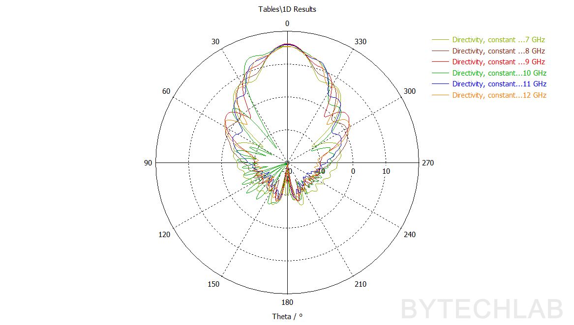
It looks like the main beam is stable and does not split up to 12 GHz, so the only thing that need major improvements to make this antenna usable above 7 GHz is the impedance matching. In the near future I will make new version of this antenna to cover wider range of frequencies (probably 2-18 GHz).
12) Conclusions
I’m very satisfied with this 3D printed double ridged horn antenna, It works extremely well. I’m sure that I will use this antenna in my RF related projects in the future. I’m surprised with high efficiency of this antenna – I’d expect higher loss due to using conductive paint. The cost to manufacture one antenna is about 30-40 USD which is also great when comparing to the commercially available products.
13) References
- [1] F. Oktafiani, E. Y. Hamid and A. Munir, “Wideband Dual-Polarized 3D Printed Quad-Ridged Horn Antenna,” in IEEE Access, vol. 10, pp. 8036-8048, 2022, doi: 10.1109/ACCESS.2022.3143164. LINK: https://ieeexplore.ieee.org/document/9681877,