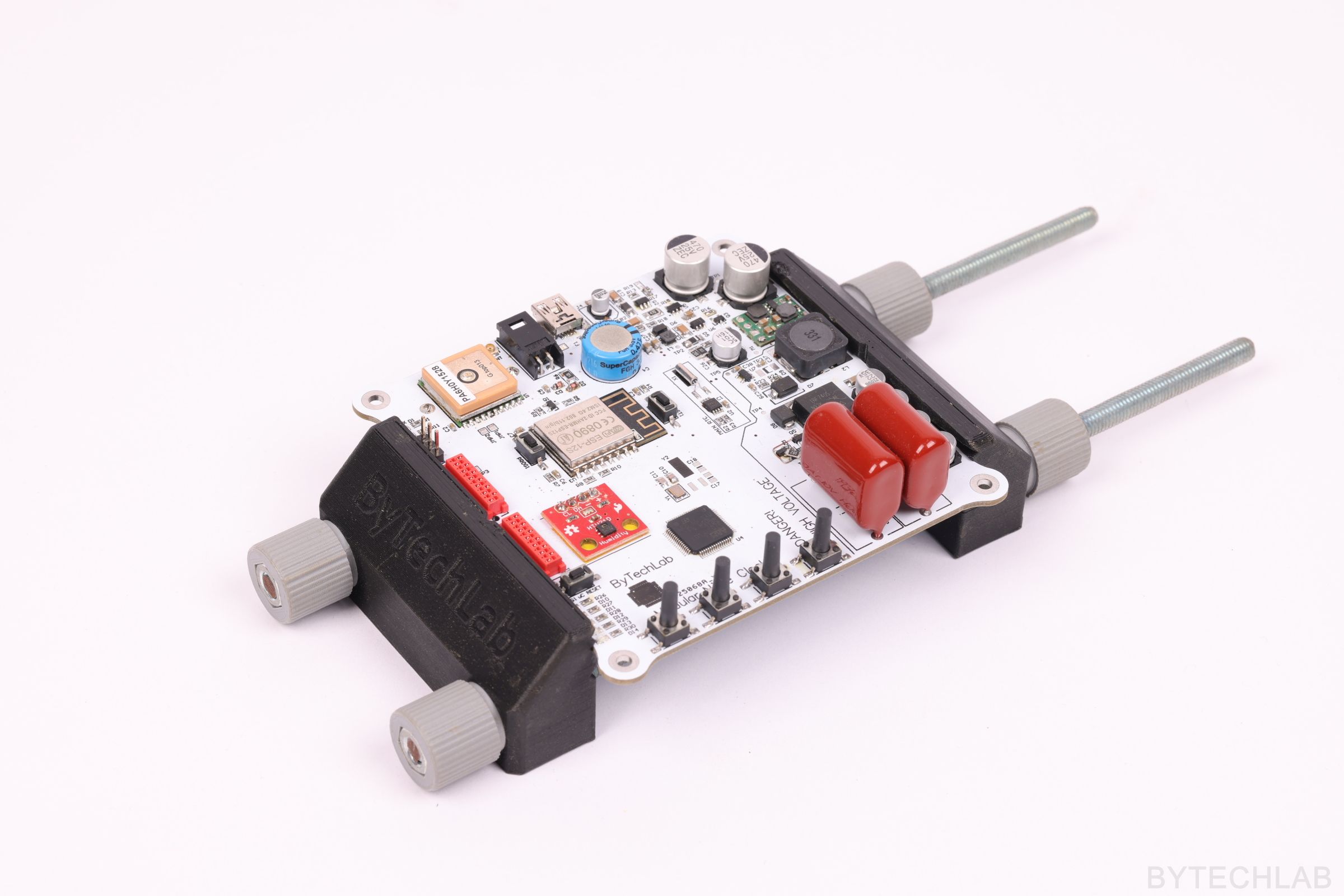
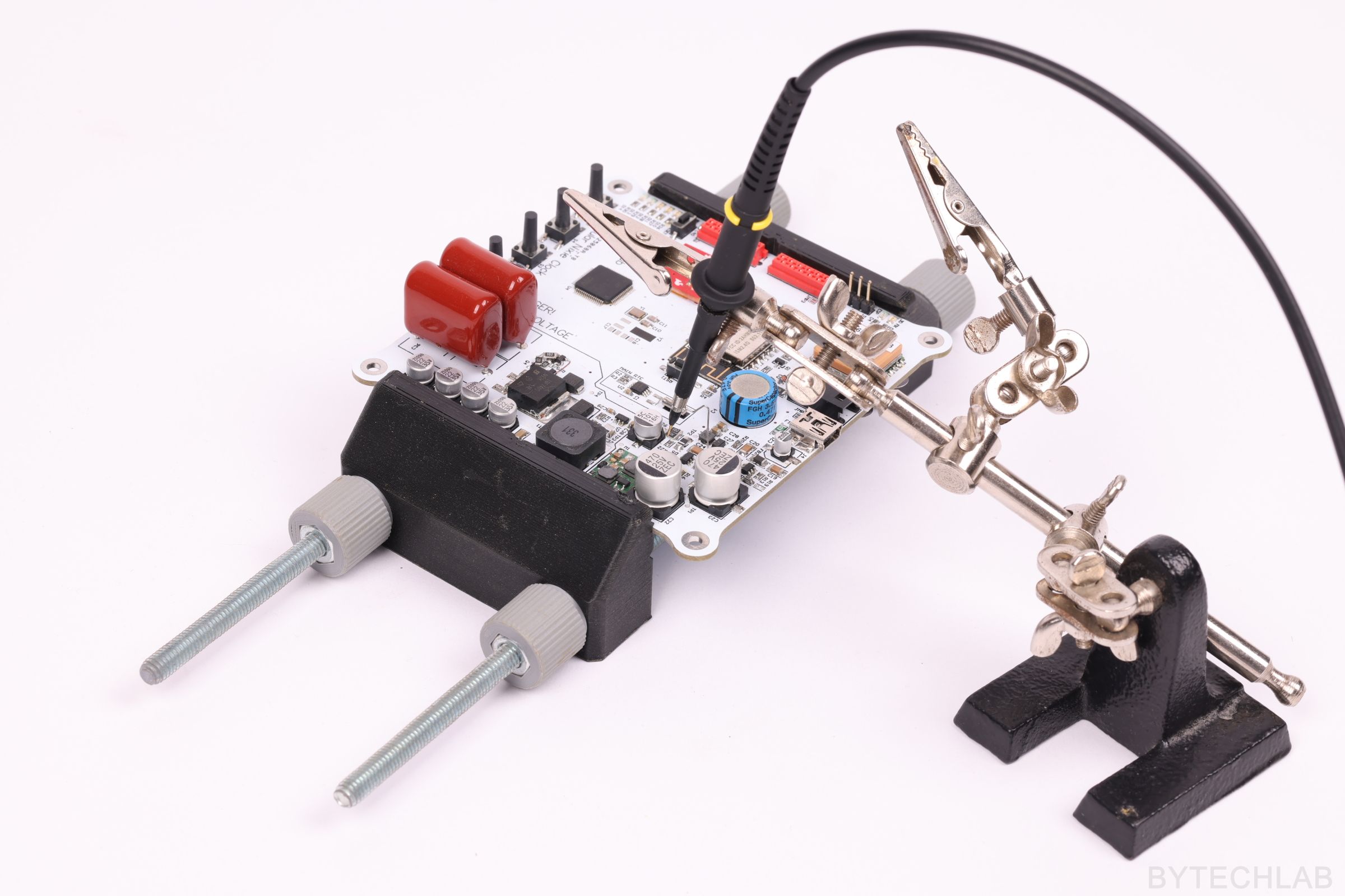
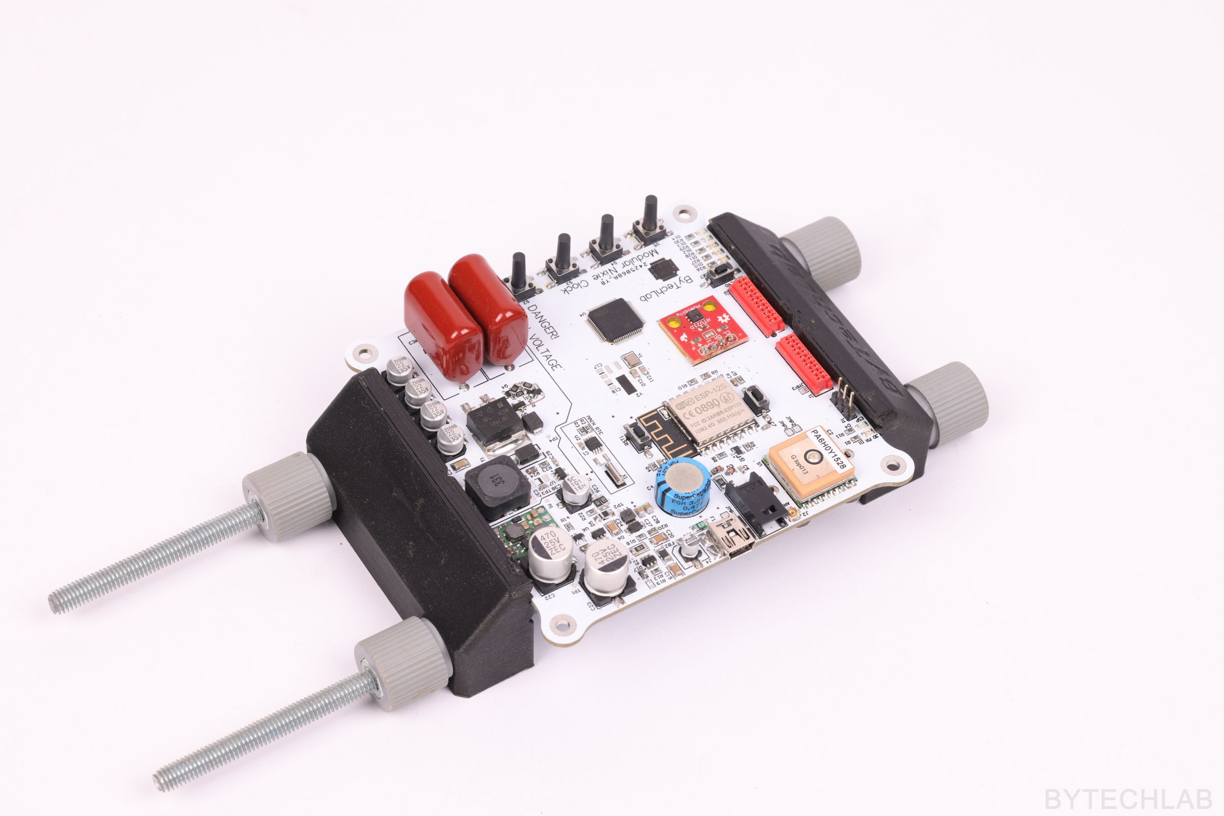
Below I will present a very useful tool in every electronics lab – a 3D Printed PCB Vise. Often you will need to hold the printed circuit board during soldering or testing.
When you have soldered big components that are sticking out from the PCB all operations that you have to make on the PCB are getting very difficult. It is almost impossible to make it lay flat for further soldering or testing.
I’m not the first person who is trying to make an PCB holding tool – there are a lot of vises and other holders on Thingiverse. However, I haven’t found any project that is suitable for me. That’s why I’ve decided to design it on my own.
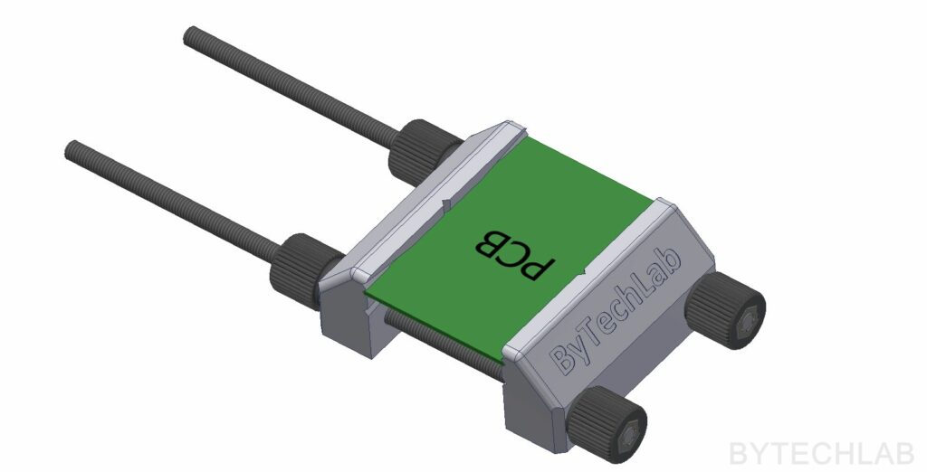
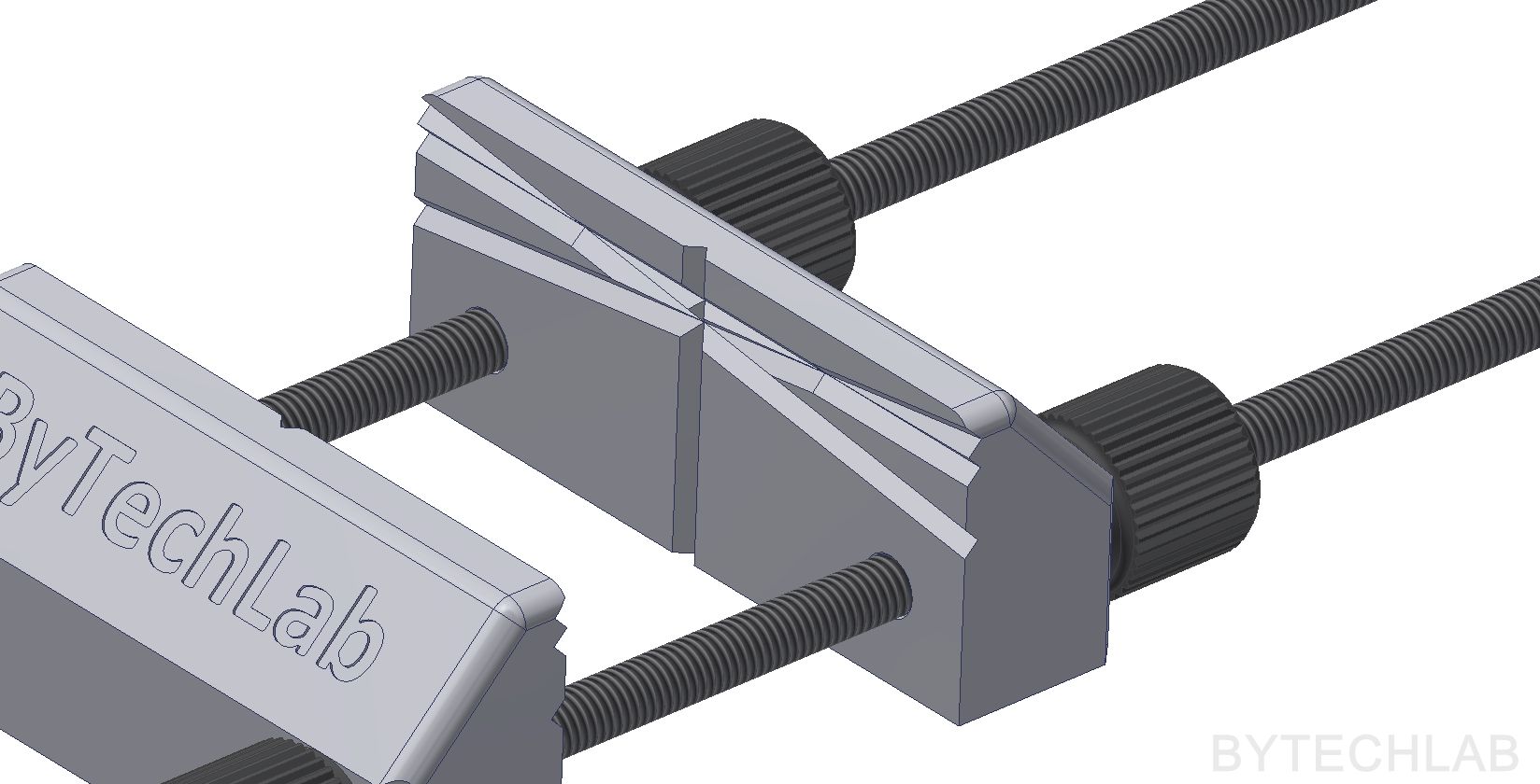
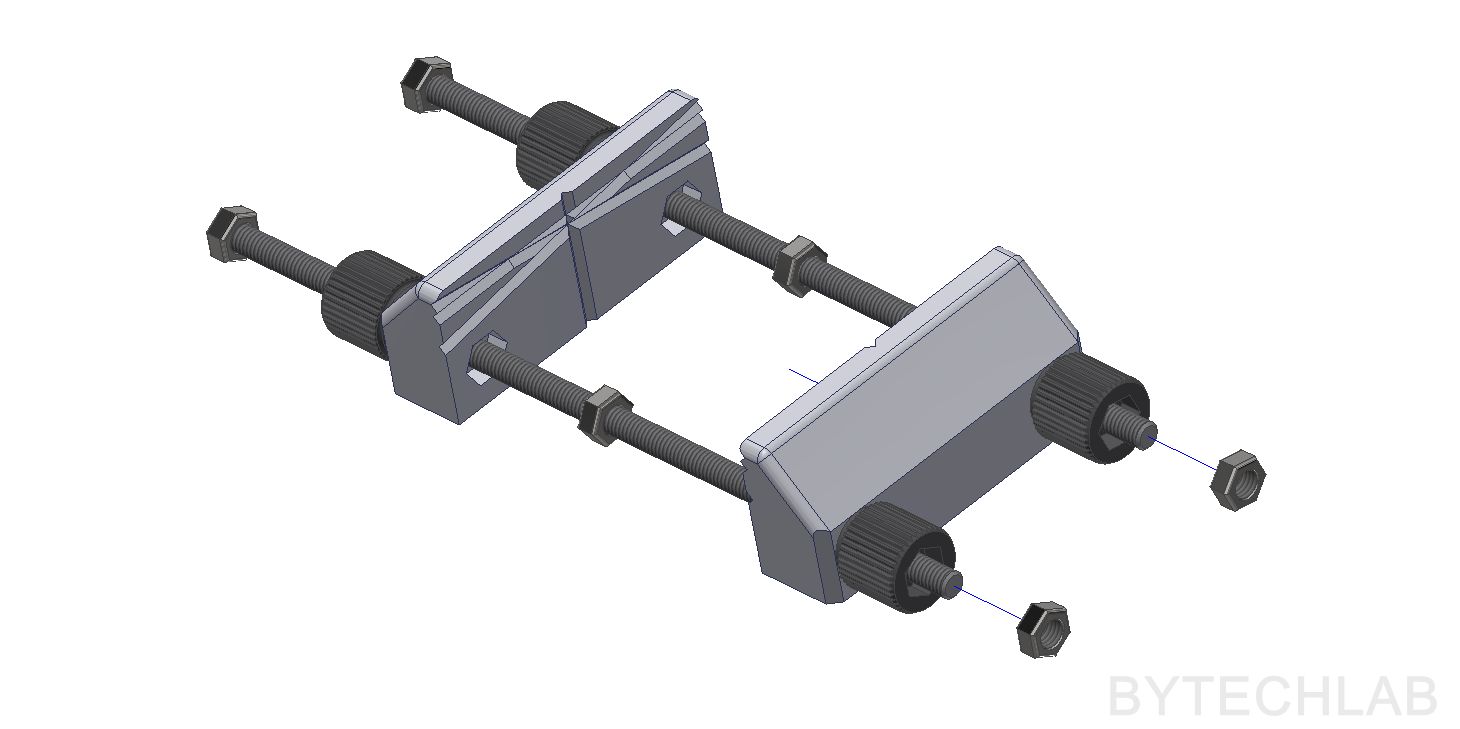
It took about 2.5 hours to complete the whole project (including printing). The vise consists only from 3 different 3D printed parts and 2 M6 threaded rods with 6 nuts – it is very easy to make one. Four of six nuts have additionally printed knobs that tightly fit on them. The vise has V-shaped grooves compatible with PCB,s up to 2.5 mm thick. The PCB can be mounted in 4 planes (tilted, vertical, horizontal).
In addition, there are holes for cylindrical neodymium magnets 10 x 4 mm at the bottom (press-fit). This vise was designed in that way to be relatively easy to print on a FDM 3D printer. It is quite small – only 75 mm in width and 32 mm in height so it doesn’t take much valuable space in your LAB.
I want to use it for hot-air soldering in the future, but I will probably need to slightly redesign it and print it from a temperature-resistant material (eg. poly carbonate).
MCAD DESIGN & 3D PRINTING
The 3D Printed PCB Vise mechanical parts were designed in Autodesk Inventor. All parts were optimized for FDM 3D printing.
In the GitHub repository (MCAD folder) you can find the following files:
- Autodesk Inventor project,
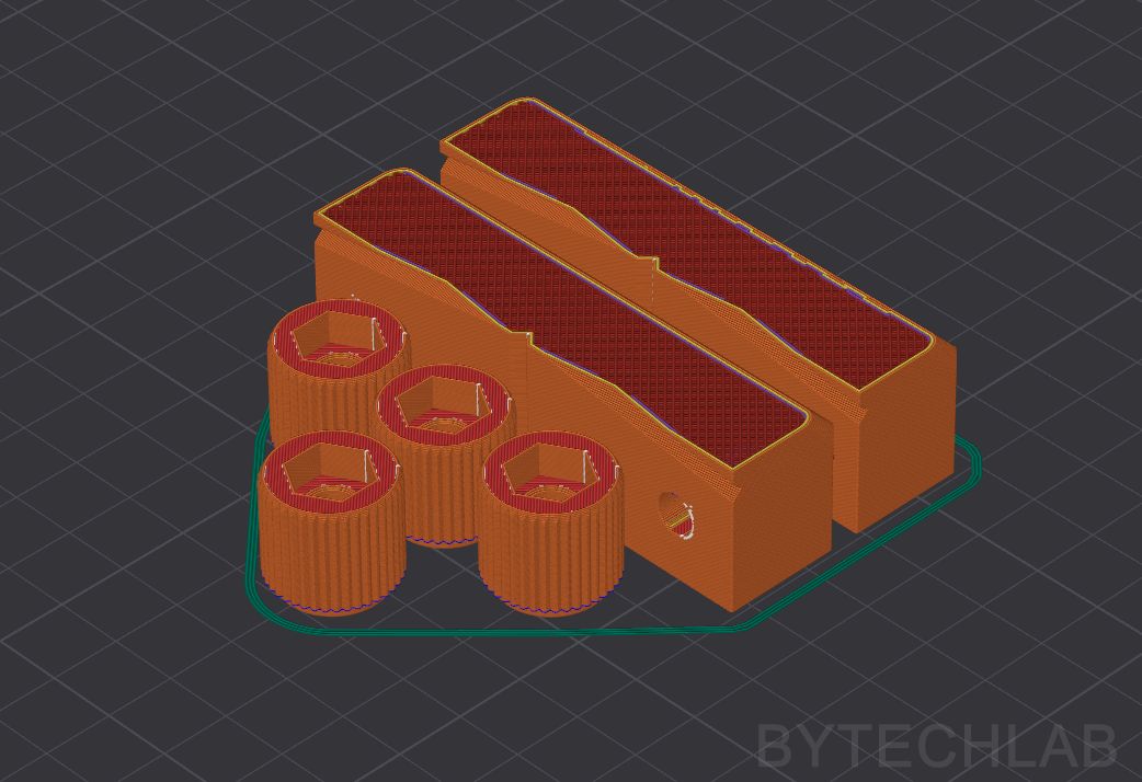
- Exported STL files for 3D printing,
- Exported STEP file of the whole assembly,
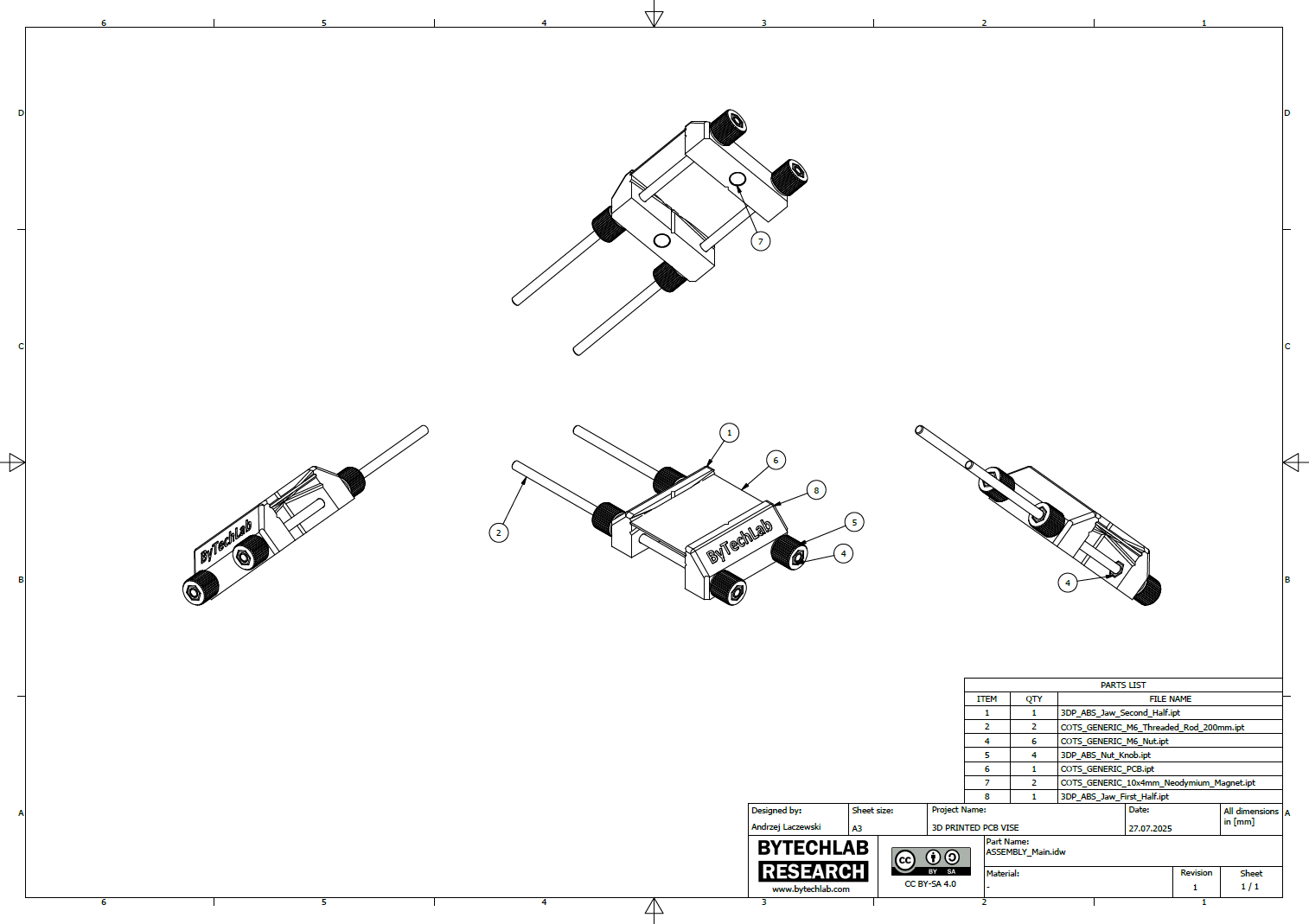
- Exported PDF file with assembly drawing, BOM and assembly instructions,
- Exported assembly renders,
- Layer height: 0.2 mm
- Printing speed: 40-60 mm/s
- Filament: ABS/ASA
- Infill: Honeycomb 30% or more
- Outlines: 2 or more
- Top/Bottom 100% layers: 3 or more
- Support: Yes – Inside the nut pockets
- Nozzle diameter: 0.4 mm
ADDITIONAL PHOTOS & RENDERS
LINK TO .STL FILES (THINGIVERSE)
https://www.thingiverse.com/thing:2797593

