
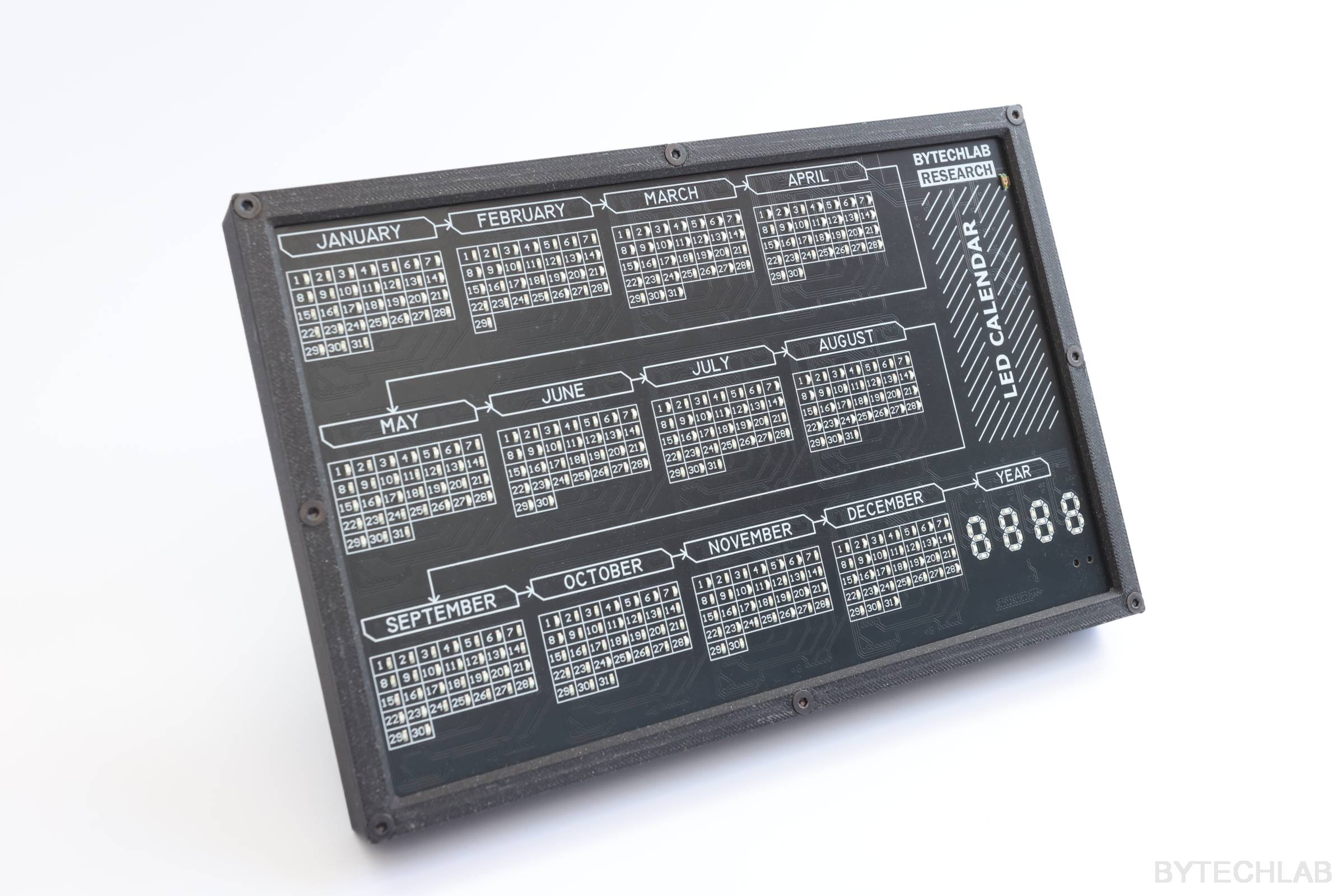
Recently I’ve noticed that the time seems to be running away from me very quickly. Nowadays we live in such a hurry that it’s hard to keep up how much time is gone and how much time we have left. It’s easier for me to keep track of the time left when I have a clear visual representation of it & I’m looking at it every day. To solve this problem I’ve designed a ESP8266 based LED Calendar.
This calendar is motivating me to do more stuff that I’ve planned to do for a given year ( you look at this calendar and say “Ohhh, I wanted to do this this and this during this year and I have only 3 months left – I need to speed up” 🙂 .
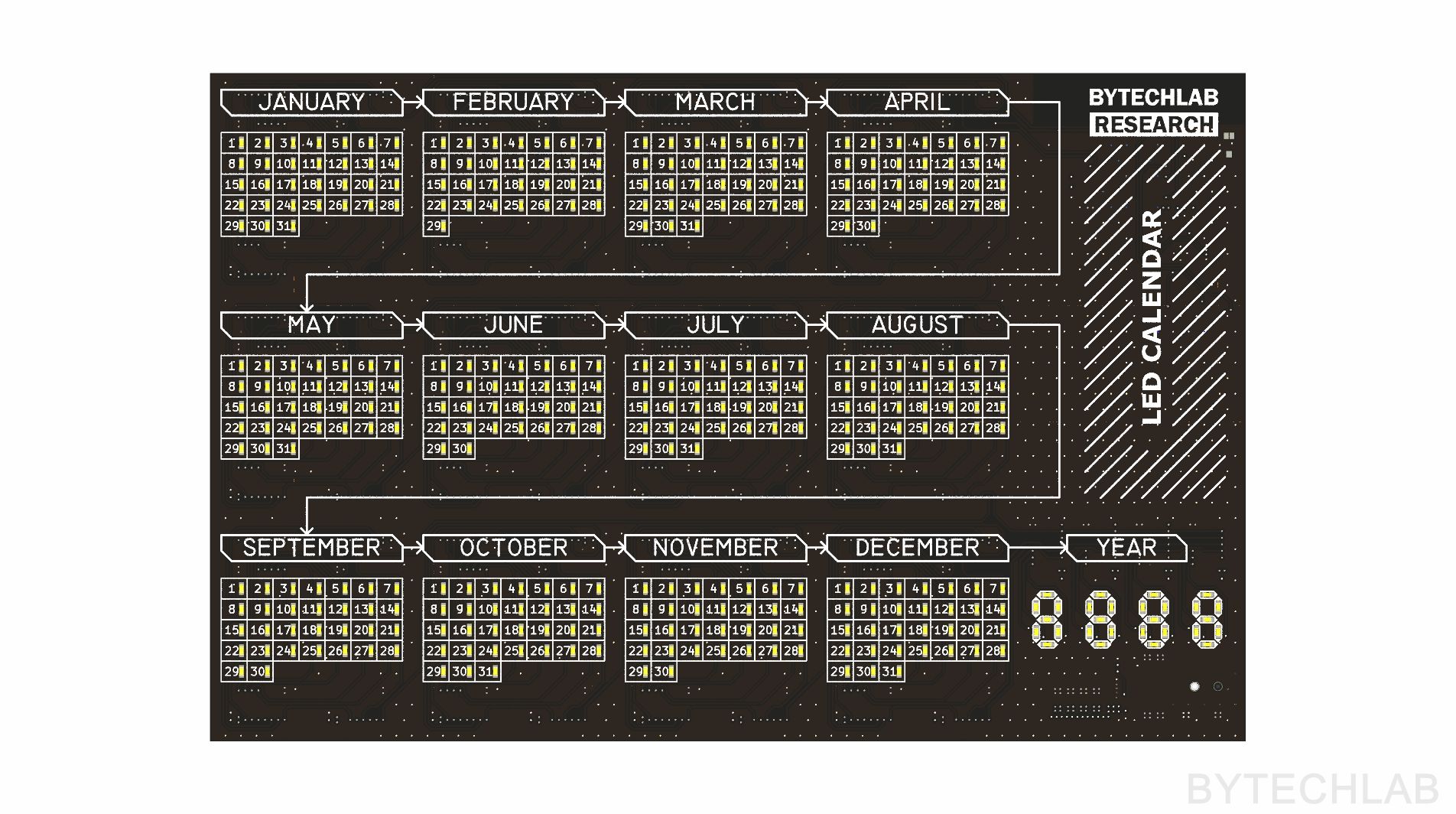
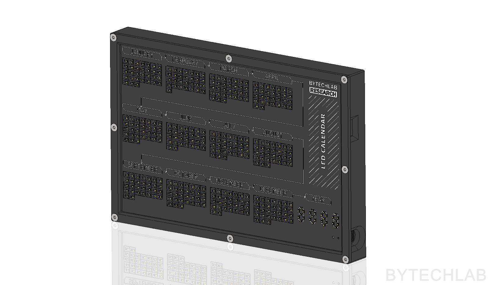
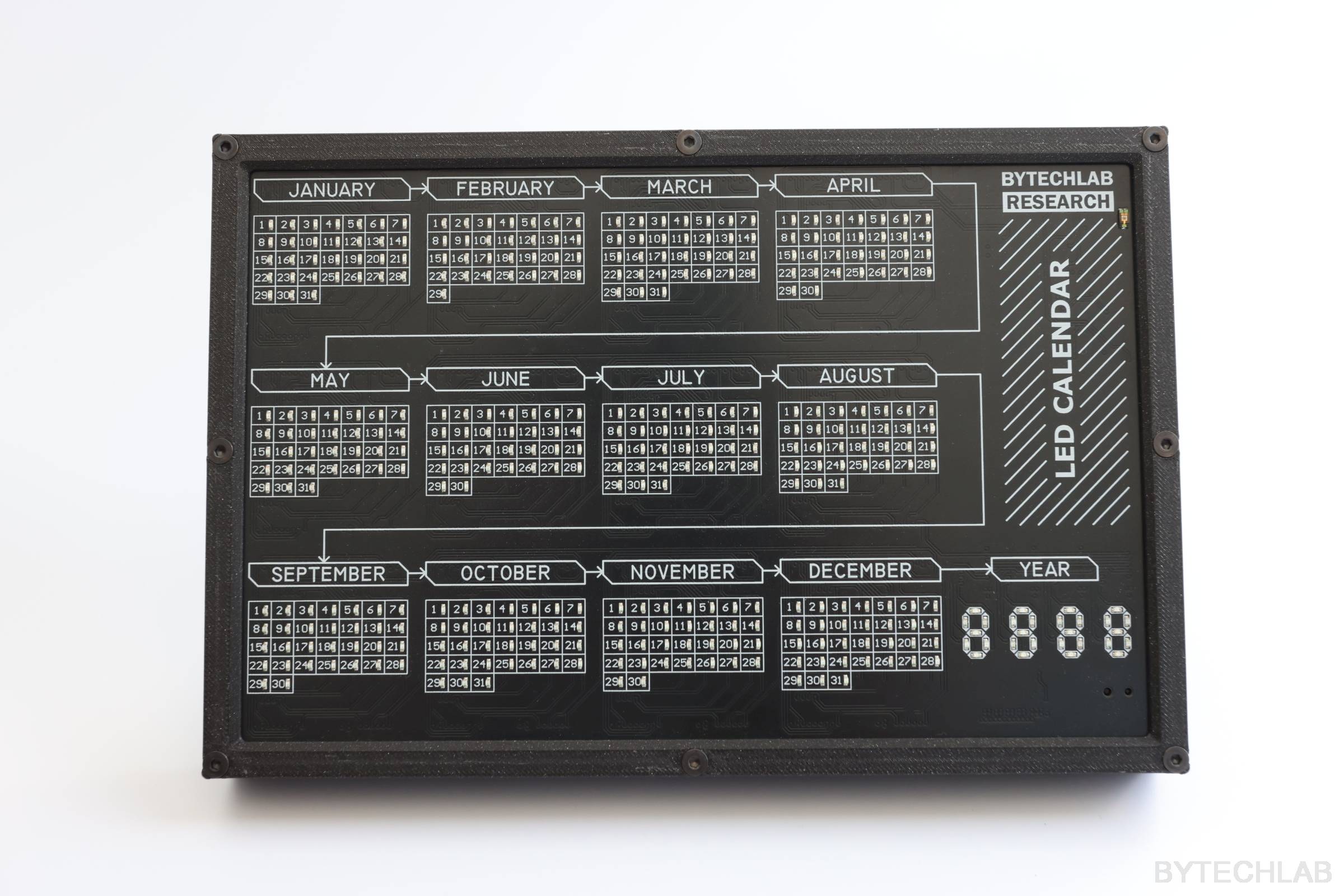
LED Calendar features:
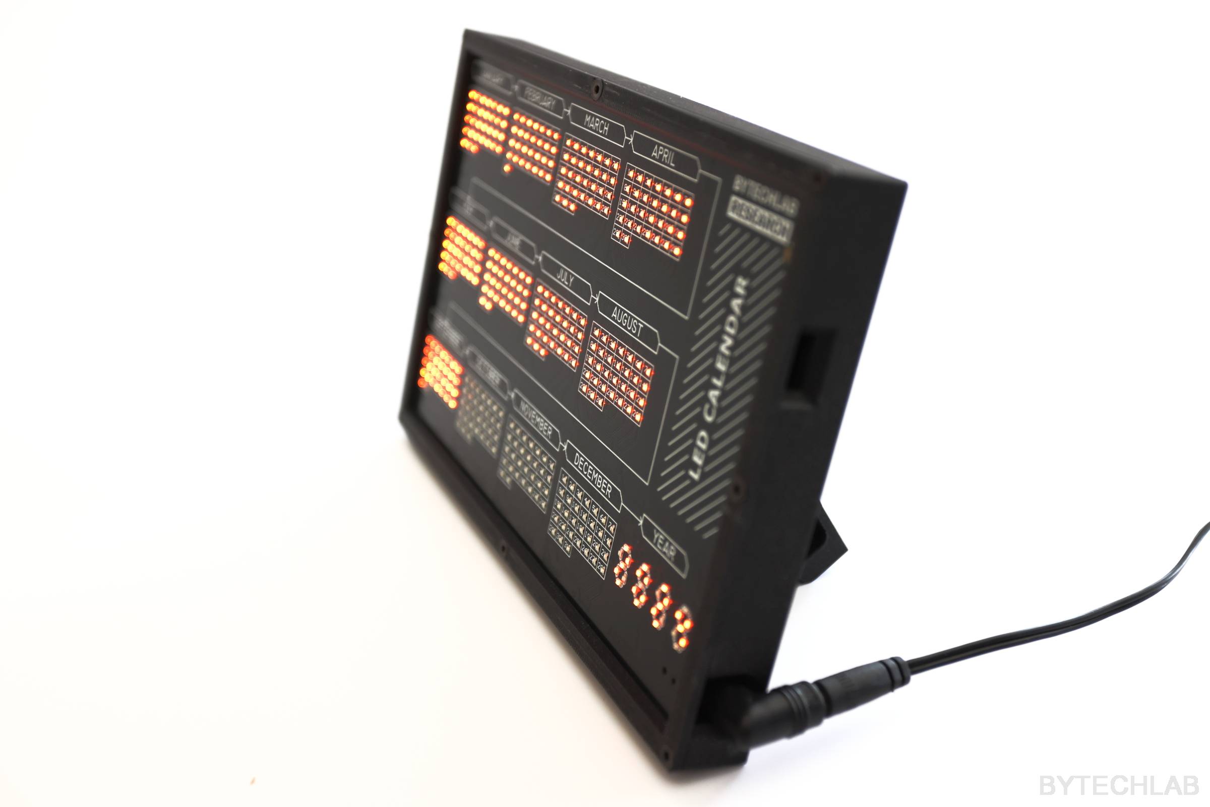
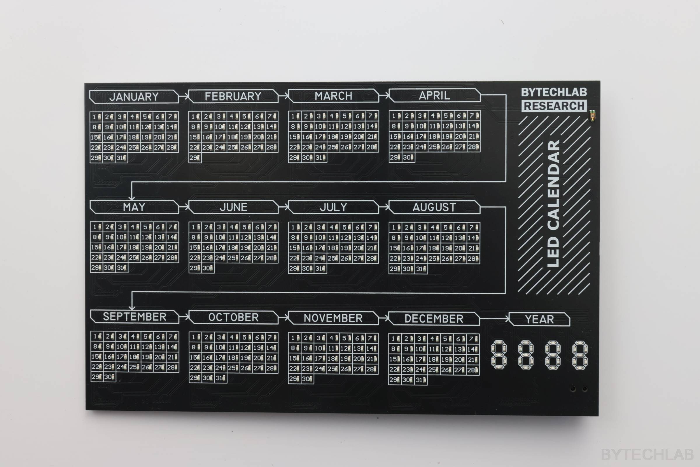
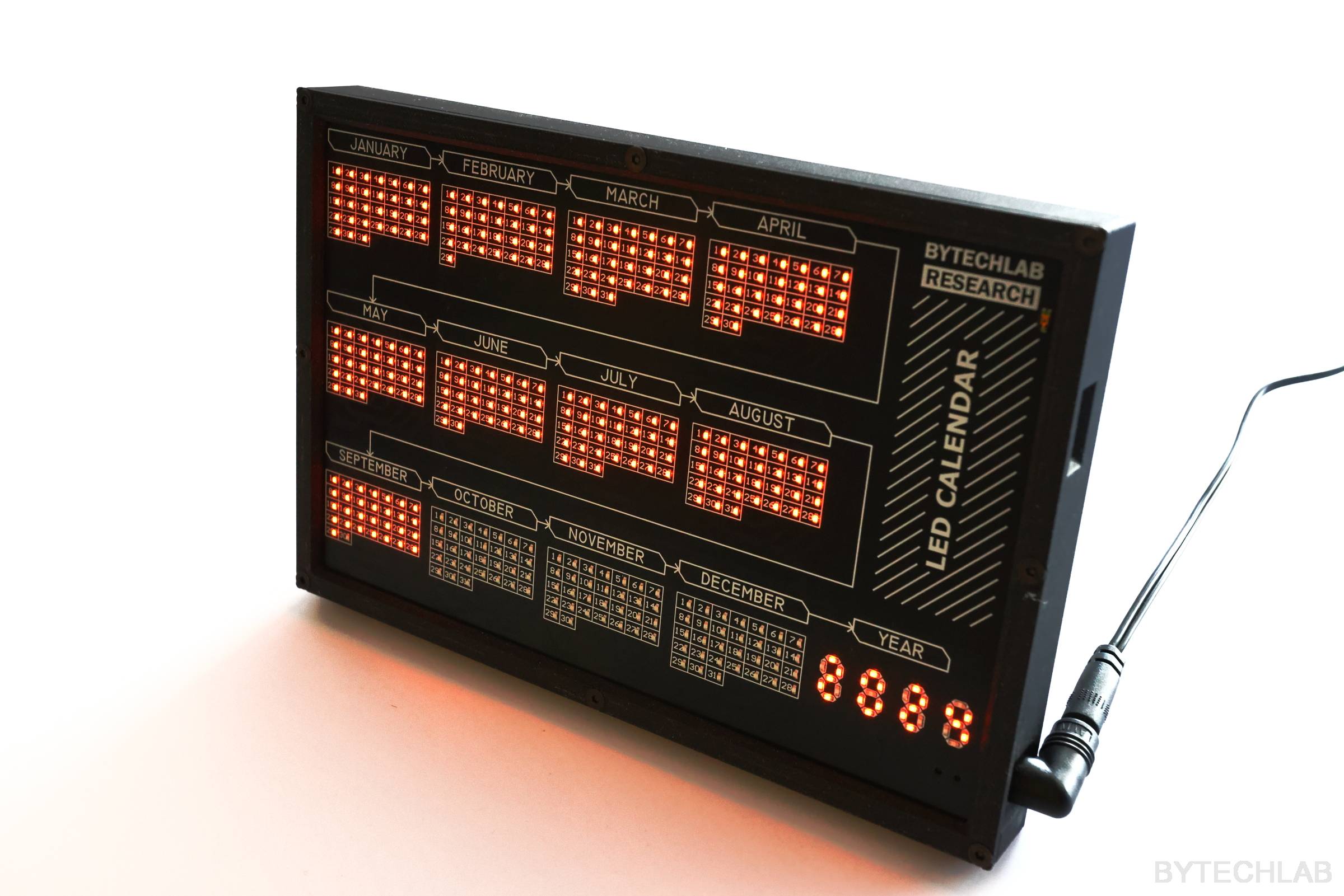
- Each day in the year has it’s own LED. Days that are gone are lit up continuously. Current day is blinking,
- Current year 7 segment display built from LED’s,
- Low power consumption: about 0.4 W – new PCB revision will have even lower power consumption (REV1 has a dummy load resistor to reduce the DC/DC converter coil whine),
- Ambient light sensor: LED calendar is measuring the ambient light intensity and adjusting the LED’s brightness accordingly with use of PWM,
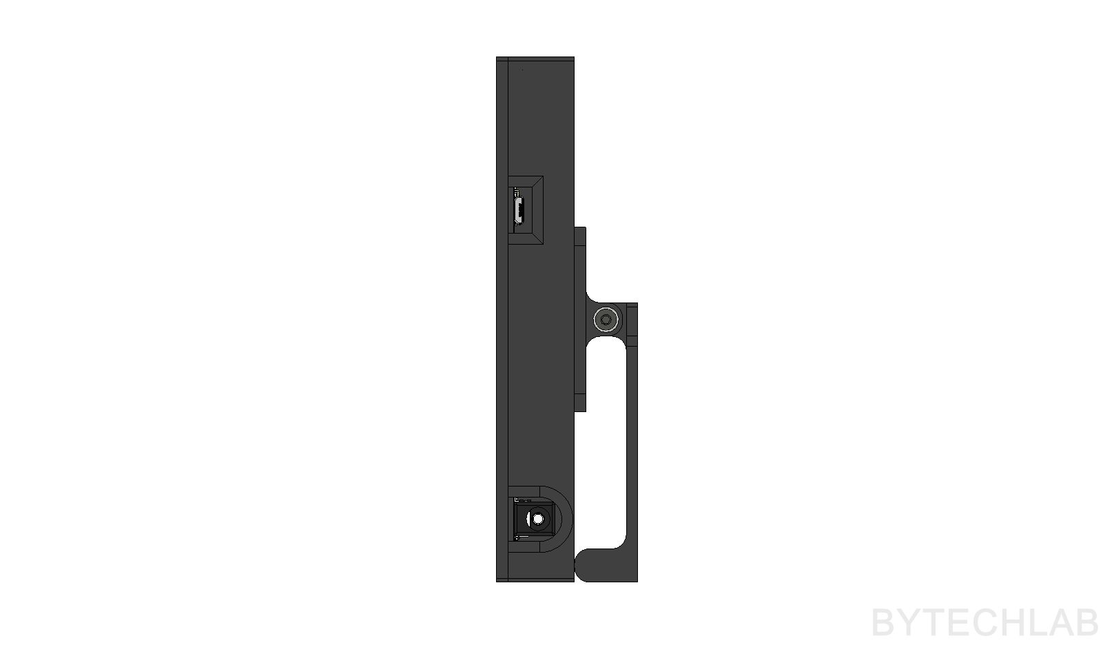
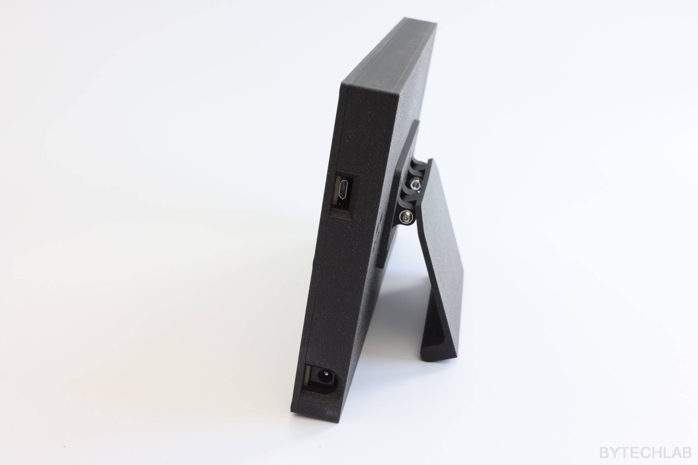
- 12- 24 V 5.5 x 2.55mm DC Jack power supply input,
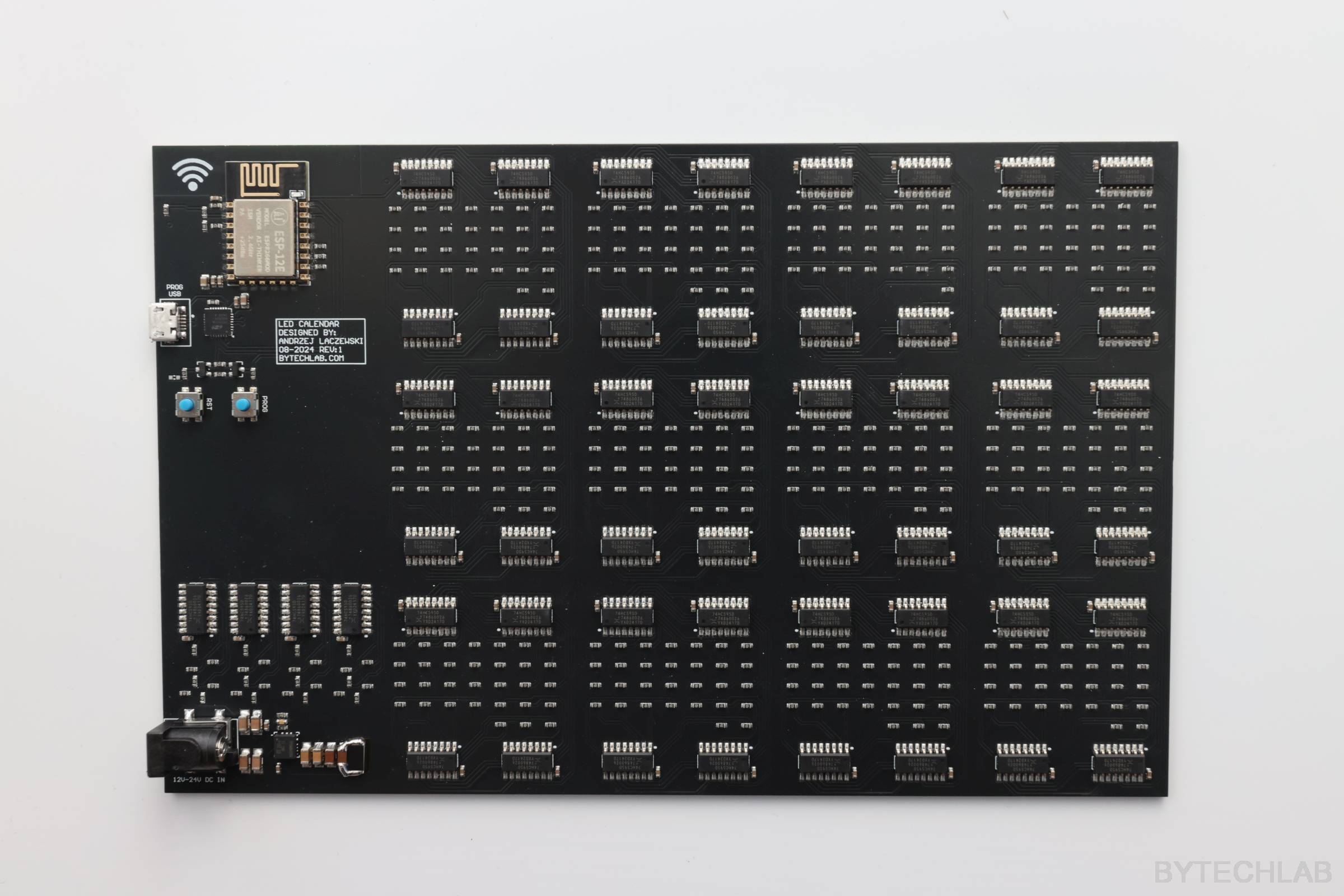
- Built in NodeMCU based ESP8266 programmer circuit: ESP8266 can be programmed directly from Arduino via micro-usb cable,
- WiFi connection to receive current time from NTP server,
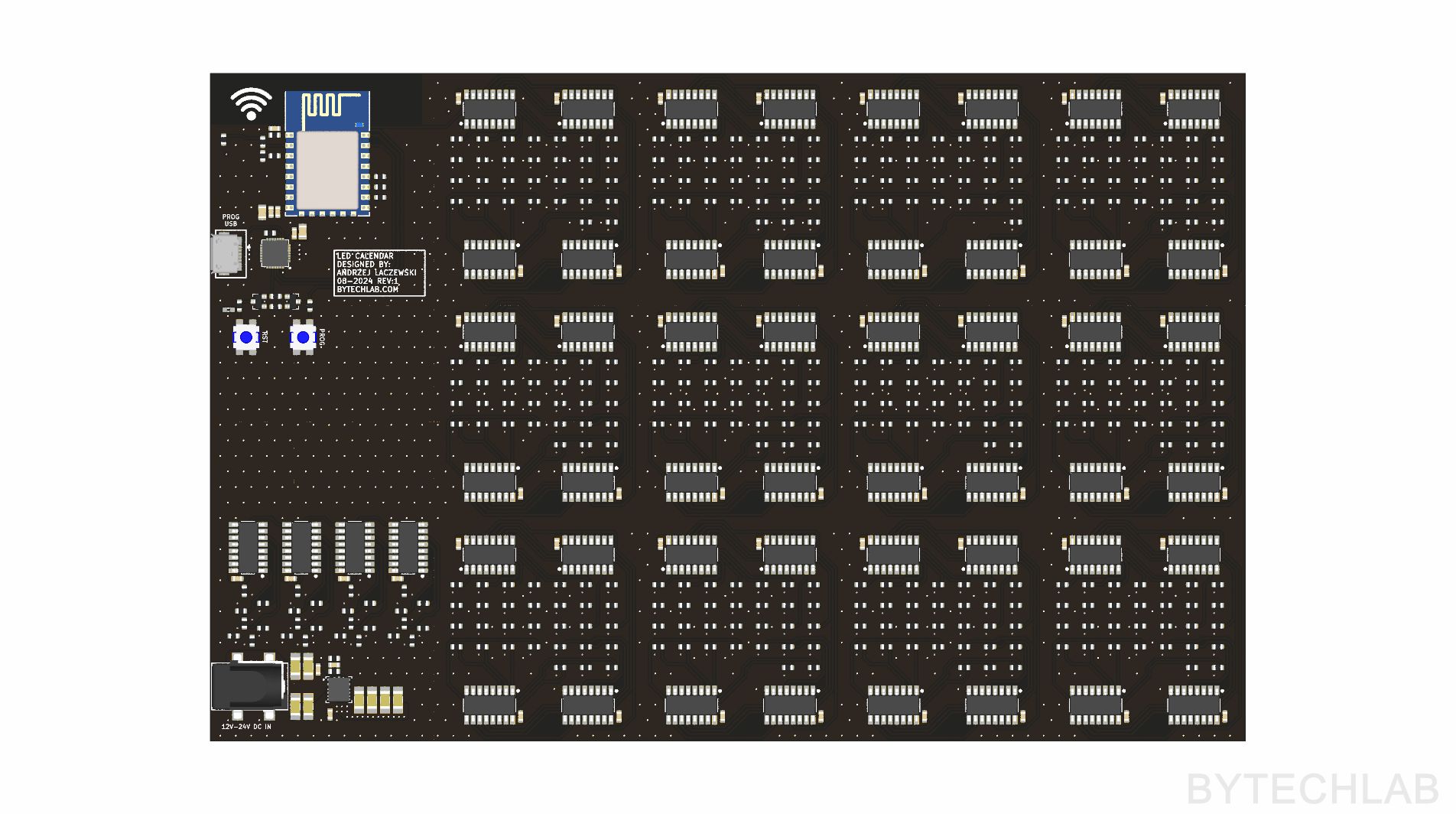
ECAD DESIGN & PCB
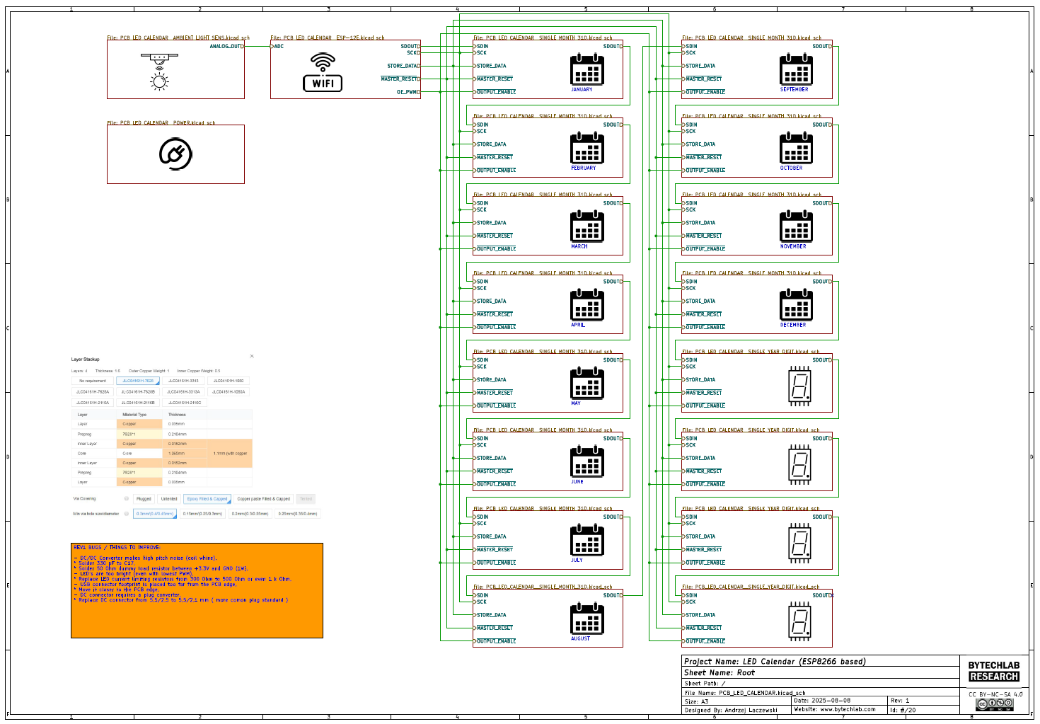
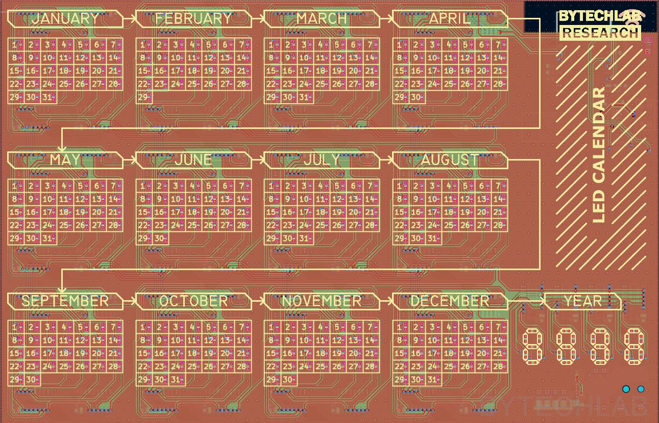
The PCB was designed in KiCAD. It was manufactured & assembled by JLCPCB. Almost all of the components were chosen from the JLCPCB inventory. There are only two parts that were not assembled by JLCPCB (USB and DC Jack connector) because they were out of stock. It is a 4 layer design to reduce the manufacturing cost & time.
In the GitHub repository (ECAD folder) you can find the following files:
- KiCAD project,
- Exported Gerber files,
- Exported BOM & P&P files,
- Exported PDF file with schematics & layout,
- Exported .STEP file of the PCB,
I have used a hierarchical schematics to speed up the PCB layout design.
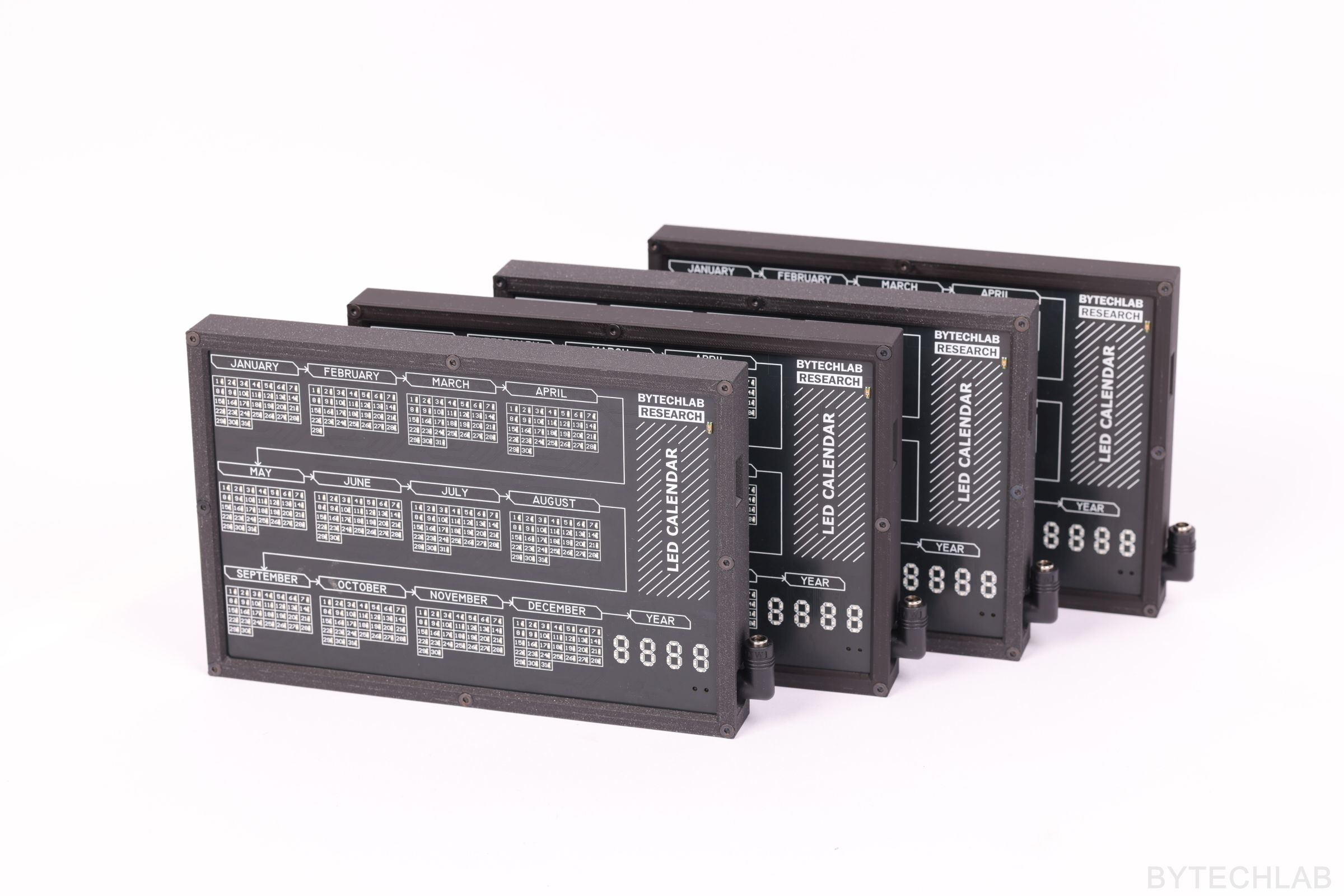
The quality of the PCB’s assembled by JLCPCB is great !. The only thing to do left is to solder the missing connectors, depanel PCB and flash the firmware into ESP8266.
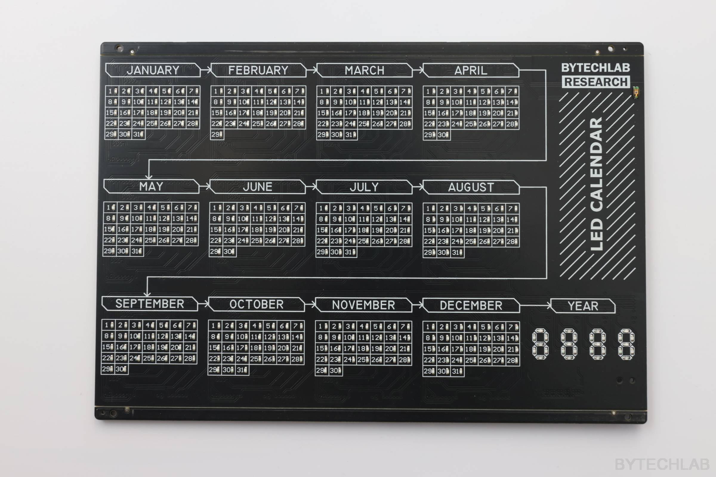
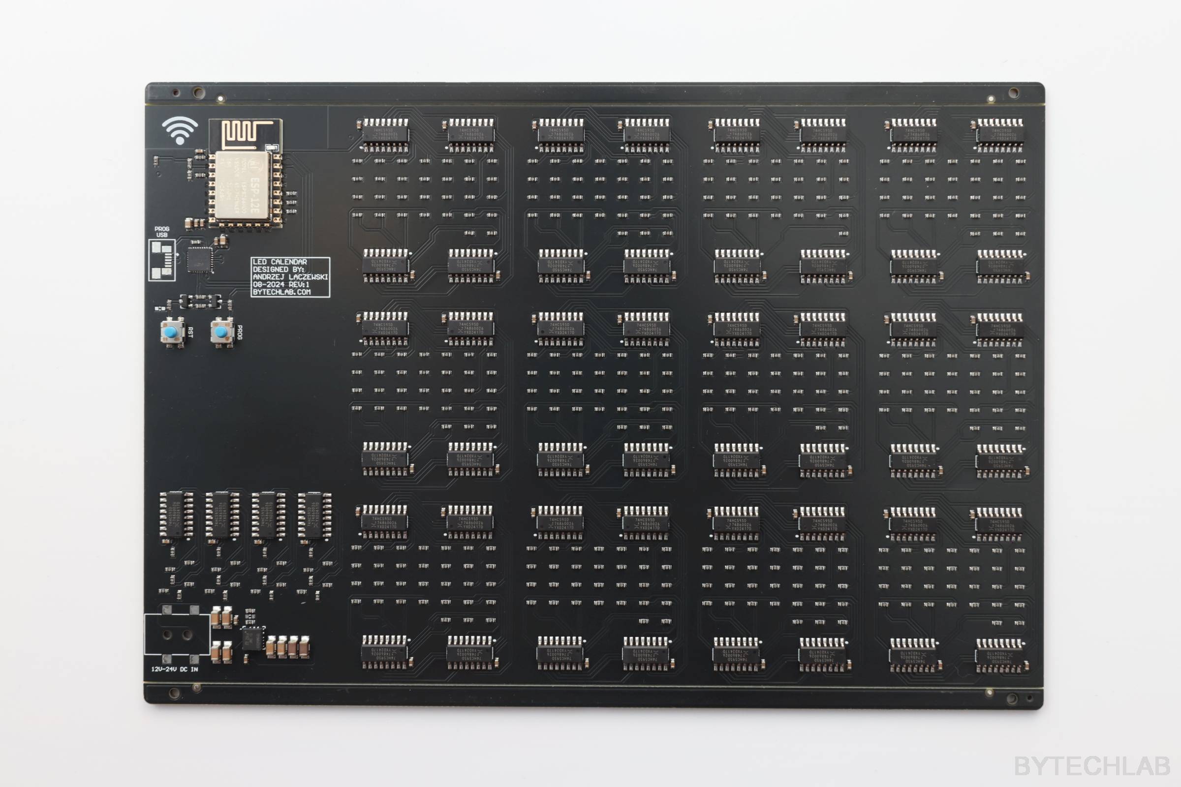
Below you can see the finished PCB’s. Additionally you can spot small modification on the bottom left corner (dummy load resistor soldered at the output capacitors of the DC/DC converter to reduce coil whine).
MCAD DESIGN & 3D PRINTING
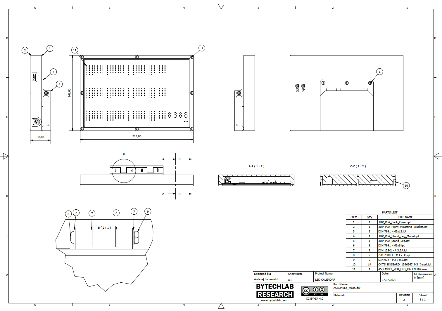
Mechanical parts were designed in Autodesk Inventor. All parts were optimized for FDM 3D printing.
In the GitHub repository (MCAD folder) you can find the following files:
- Autodesk Inventor project,
- Exported STL files for 3D printing,
- Exported STEP file of the whole assembly,
- Exported PDF file with assembly drawing, BOM and assembly instructions,
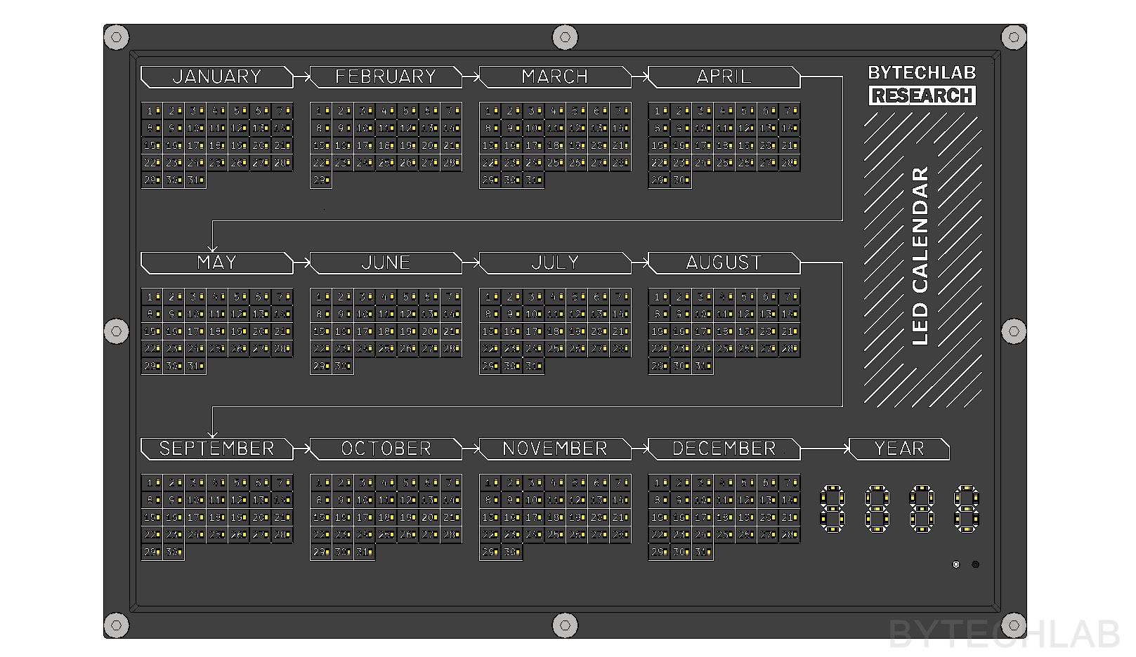
- Exported calendar renders,
There are 4 parts to be 3D printed in total. I have printed all of the parts on my favorite BambuLab X1C + AMS.
Recommended printing settings:
- 0.2 mm layer height,
- PLA filament (black onyx),
- 40 % rectilinear infill,
LED Calendar FIRMWARE
Firmware was written in Arduino environment (mainly because of good integration with NodeMCU programmer & lots of libraries that are easy to use).
The firmware is available in the GitHub repo in FIRMWARE\2_CALENDAR_CODE folder.
The only thing that you will need to do is to change your WiFi SSID, Password & Set your timezone offset:
// ---------------- NTP ---------------->
// Replace with your network credentials
const char *ssid     = "YOUR_SSID";             // < -------- HERE
const char *password = "YOUR_PASSWD";           // < -------- HERE
// Set offset time in seconds to adjust for your timezone, for example:
// GMT +1 = 3600
// GMT +8 = 28800
// GMT -1 = -3600
// GMT 0 = 0
const unsigned int NTP_Timezone_Offset = 7200; //(GMT +2)      // < -------- HERE
Needed libraries & packages:
- esp8266 by ESP8266 Comunity ( board package ),
- NTPClient by Fabrice Weinberg ( library ),
Choose NodeMCU 1.0 (ESP-12E Module) board in your Arduino IDE and upload the firmware !
CALENDAR DATE CHANGE ANIMATION
Every day at 00:00 hour new day led lights up and starts blinking. To highlight this change I have added a simple date change animation.
POWER SUPPLY
For power supply I have used the following parts:
- Mean Well SGA18E12-P1J (12V / 1.5A) 18W AC-DC High Reliability Slim Wall-mounted Adaptor – It’s a overkill, you can use anything that is able to provide about 5W of power,
- Mean Well DC PLUG-P1J-P1LR right angle plug adapter,
ADDITIONAL PHOTOS
BUGS & TODO:
ECAD REV1:
- DC/DC Converter makes high pitch noise (coil whine),
- Solder 330 pF to C17,
- Solder 50 ohm dummy load resistor between +3.3V and GND (1W),
- LED’s are too bright (even with lowest PWM),
- Replace LED current limiting resistors from 300 Ohm to 500 Ohm or even 1 k Ohm,
- USB connector footprint is placed too far from the PCB edge,
- Move it closer to the PCB edge,
- DC connector requires a plug converter,
- Replace DC connector from 5,5/2,5 to 5,5/2,1 mm ( more common plug standard )
MCAD REV1:
- Putting M3 screws directly into 3D printed parts is a bad idea (like self tappers),
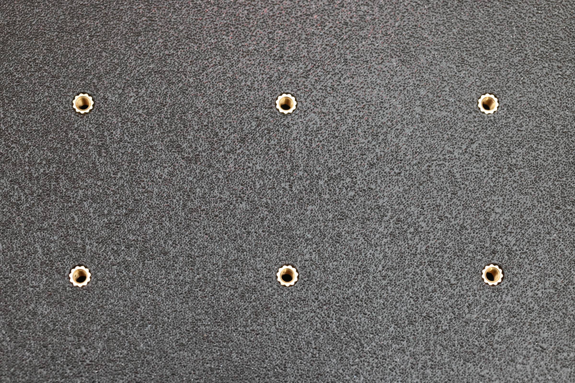
- Use M3 brass inserts,
FIRMWARE:
- Reduce NTP request frequency,
- Implement day change prediction algorithm,
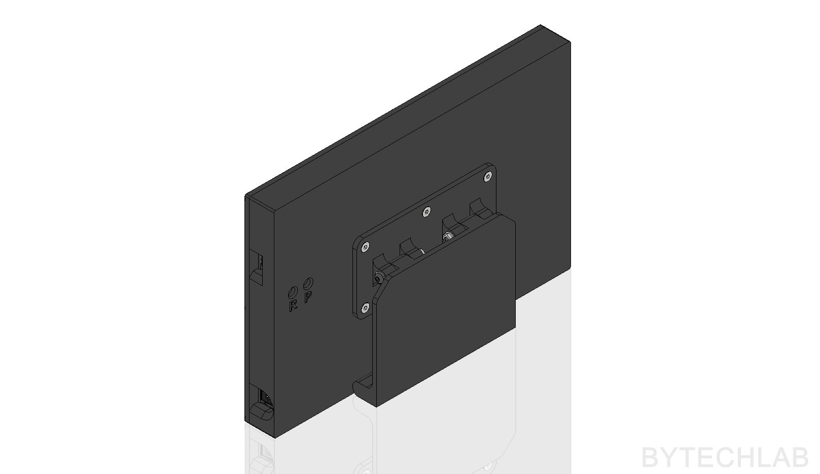
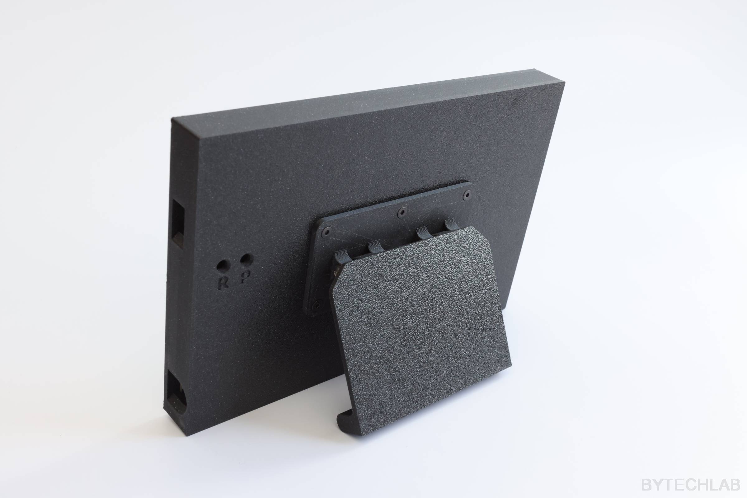
UPDATE 1: MCAD REV2
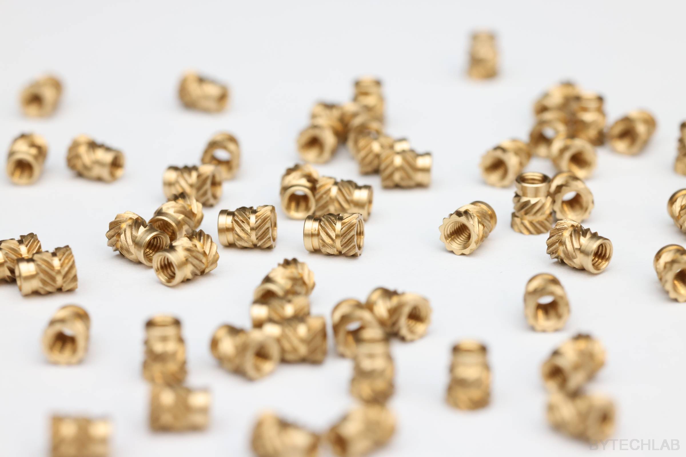
Putting M3 screws directly into 3D printed parts is a terrible idea. You can remove the screws only a couple of times before the plastic thread wears out. Also it is very hard to initially screw in the screw to form the thread in the 3D printed parts. To get rid of this problem I’ve redesigned back cover to use M3 inserts (Bossard 1386867).
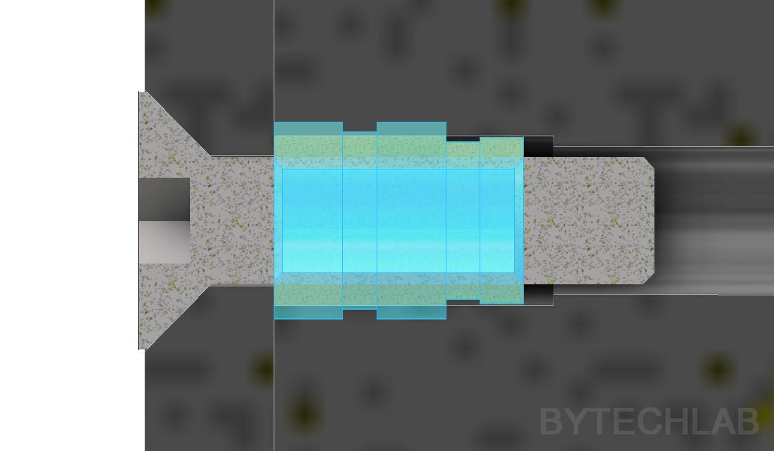
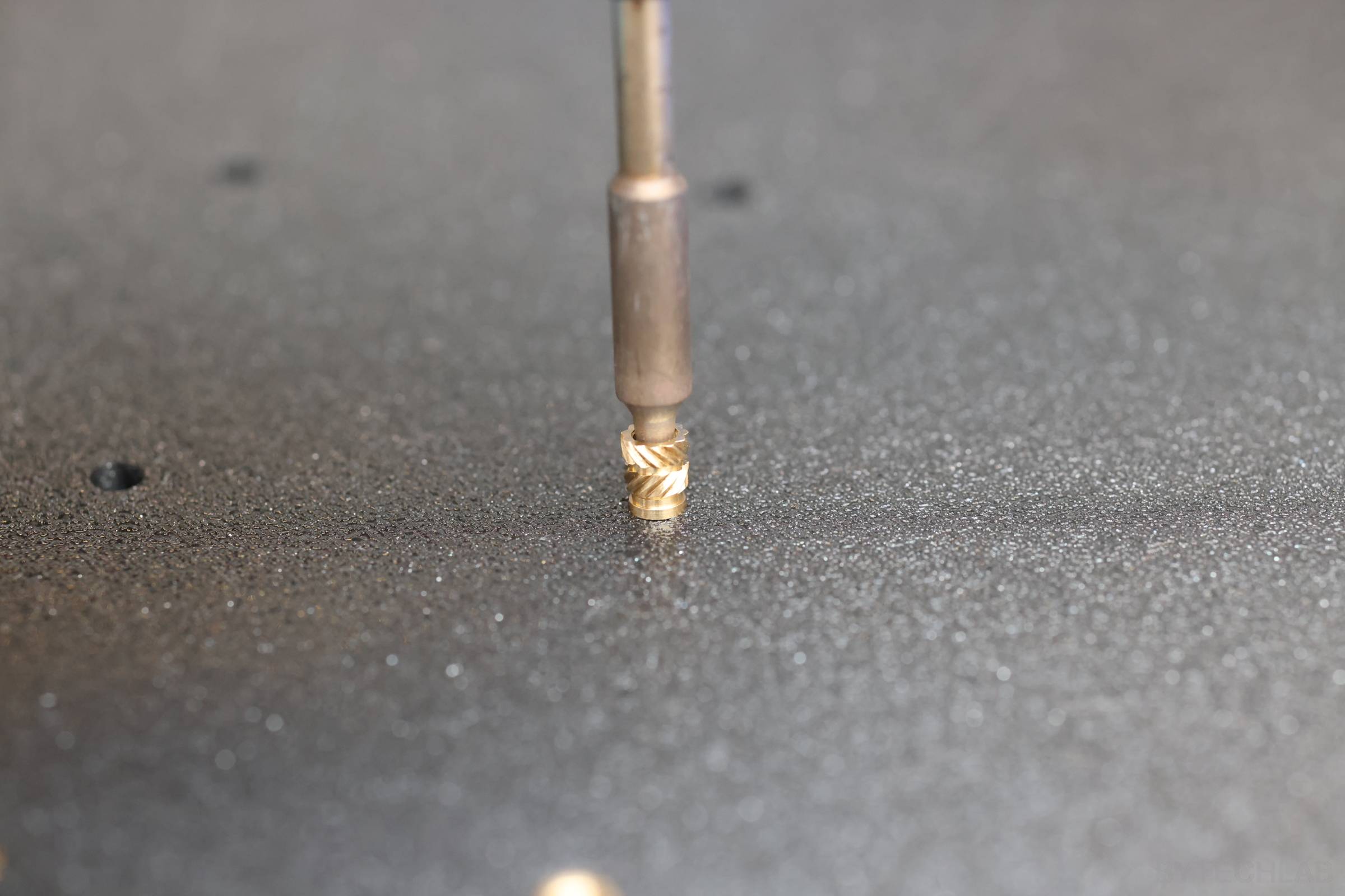
Inserts were installed with use of soldering iron set at 200 deg. C. They fit very nicely and I was surprised how hard it is to pull out these – the connection is rock solid !
SUMMARY
LED Calendar looks gorgeous, I absolutely love it 🙂 . There were some minor bugs (most of them are already fixed) and there is still some room for improvement but overall the whole project went very smoothly.