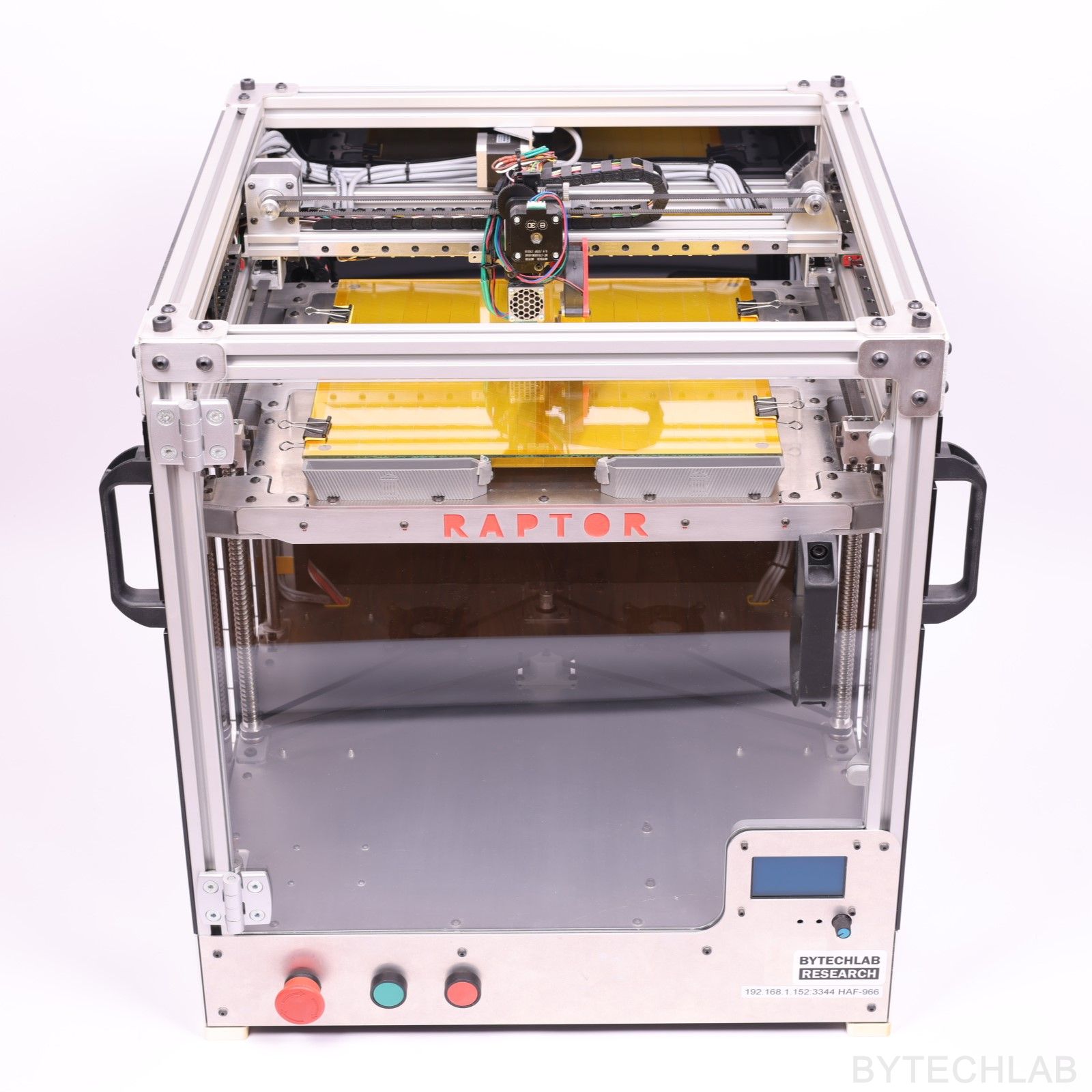
For a long time I wanted to build my own large 3D printer. I haven’t found any 3D printer that is available on the market that would fit my needs in every aspect. That was the main reason why I have started this FDM 3D Printer (RAPTOR-360) project. I tried to add to the design as many useful features as possible while keeping the price as low as possible. Most of the parts were either laser cut, 3D printed or CNC milled.
Building and designing this printer took me about half year mainly due to the lack of free time – if I could hurry up I think that I would be able to would finish it in about two months.
The printer is not 100% finished, there are still a few small parts missing. However, I think that at this point I can show you how I have designed and built this printer.
MCAD DESIGN
I have designed the whole printer in the Autodesk Inventor software. Firstly, I had to determine the size of the printing volume around which the entire printer will be built. I decided to choose a 360 x 360 mm build area (X/Y). Why? The answer to this question is very simple – I had linear rails of this length.
The hardest thing to do was to design the Z axis platform assembly in the way it is rigid enough. It wasn’t a easy thing because I had to deal with such a large build area. Once the key dimensions were known, I’ve designed other important parts (aluminium plates, plexi panels, X-axis, etc.). The entire frame is based on 30 x 30 mm aluminium extrusion profiles.
In the GitHub repository (MCAD folder) you can find the following files:
- FDM 3D Printer (RAPTOR-360) Autodesk Inventor project,
- Exported STEP file of the whole assembly,
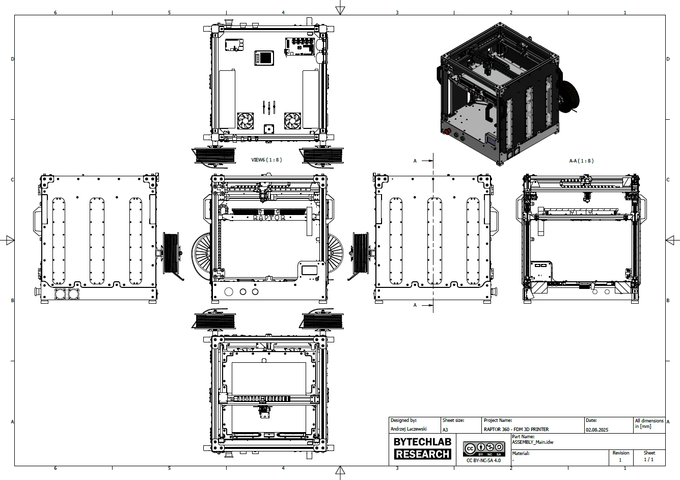
- Exported PDF file with assembly drawing,
- Exported assembly renders,
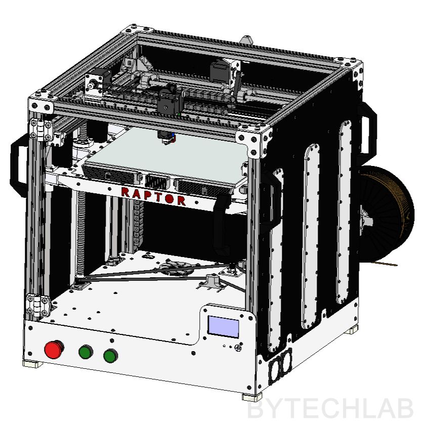
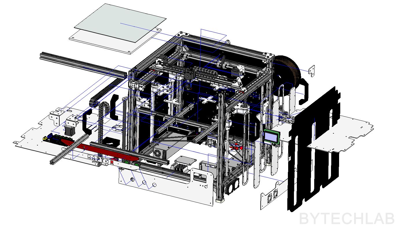
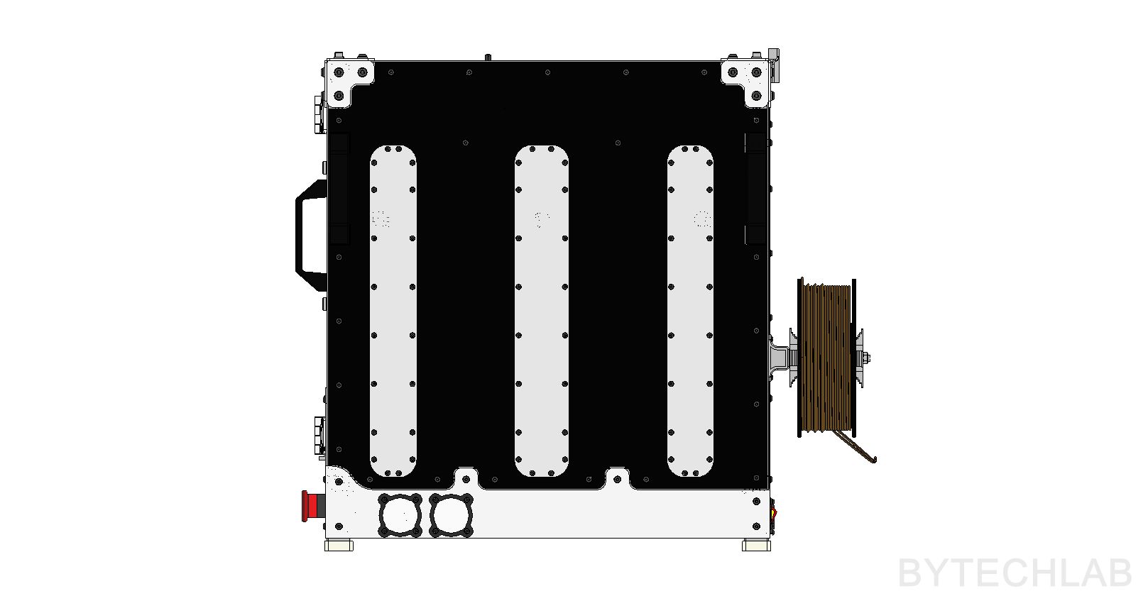
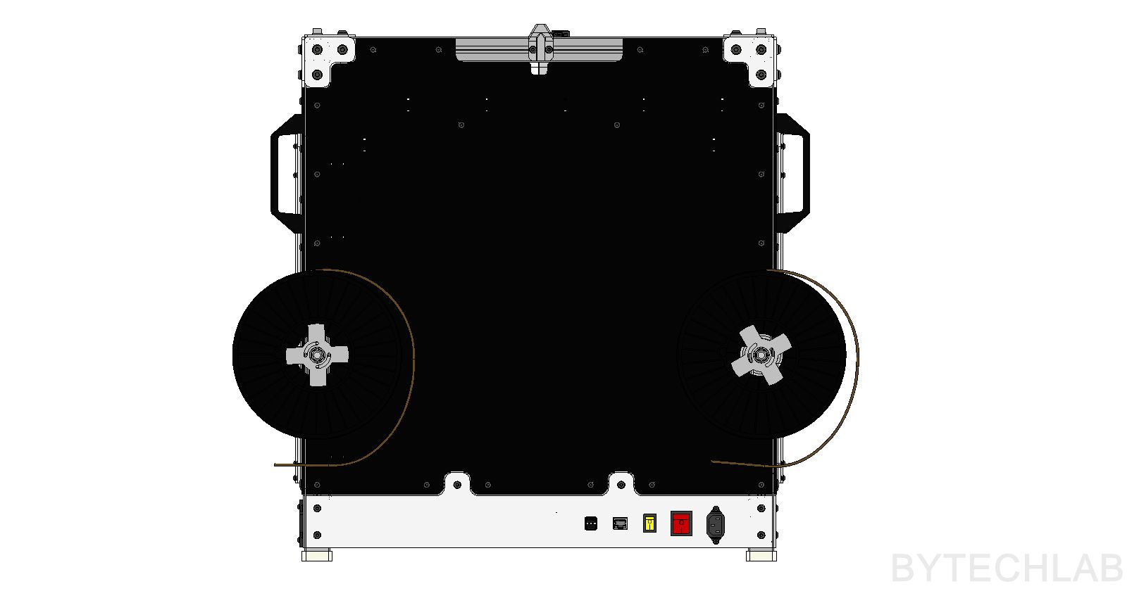
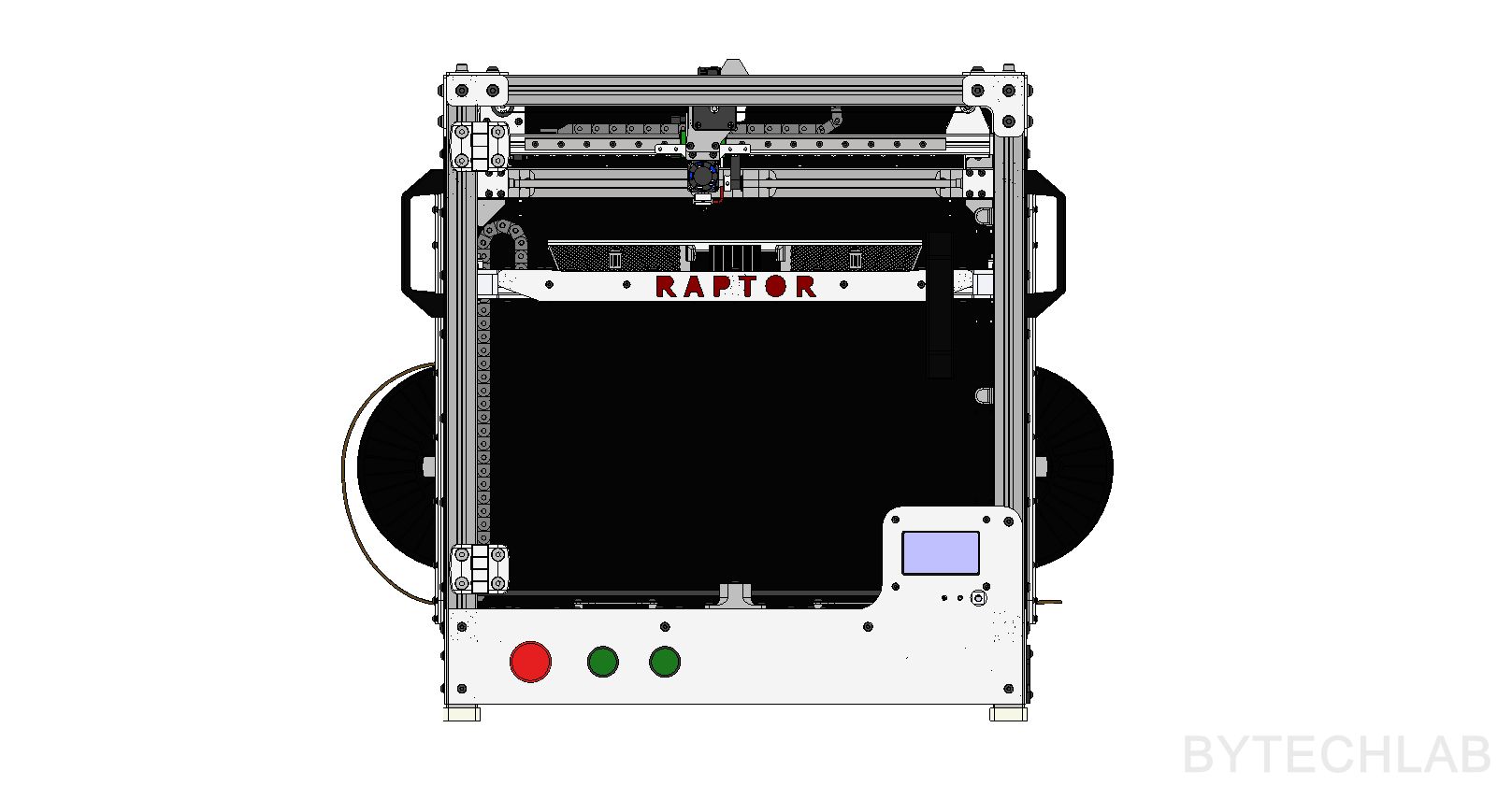
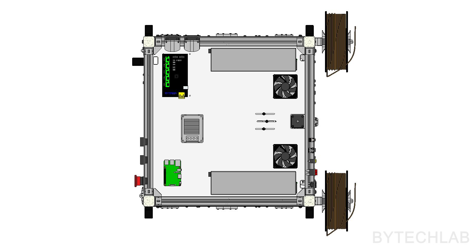
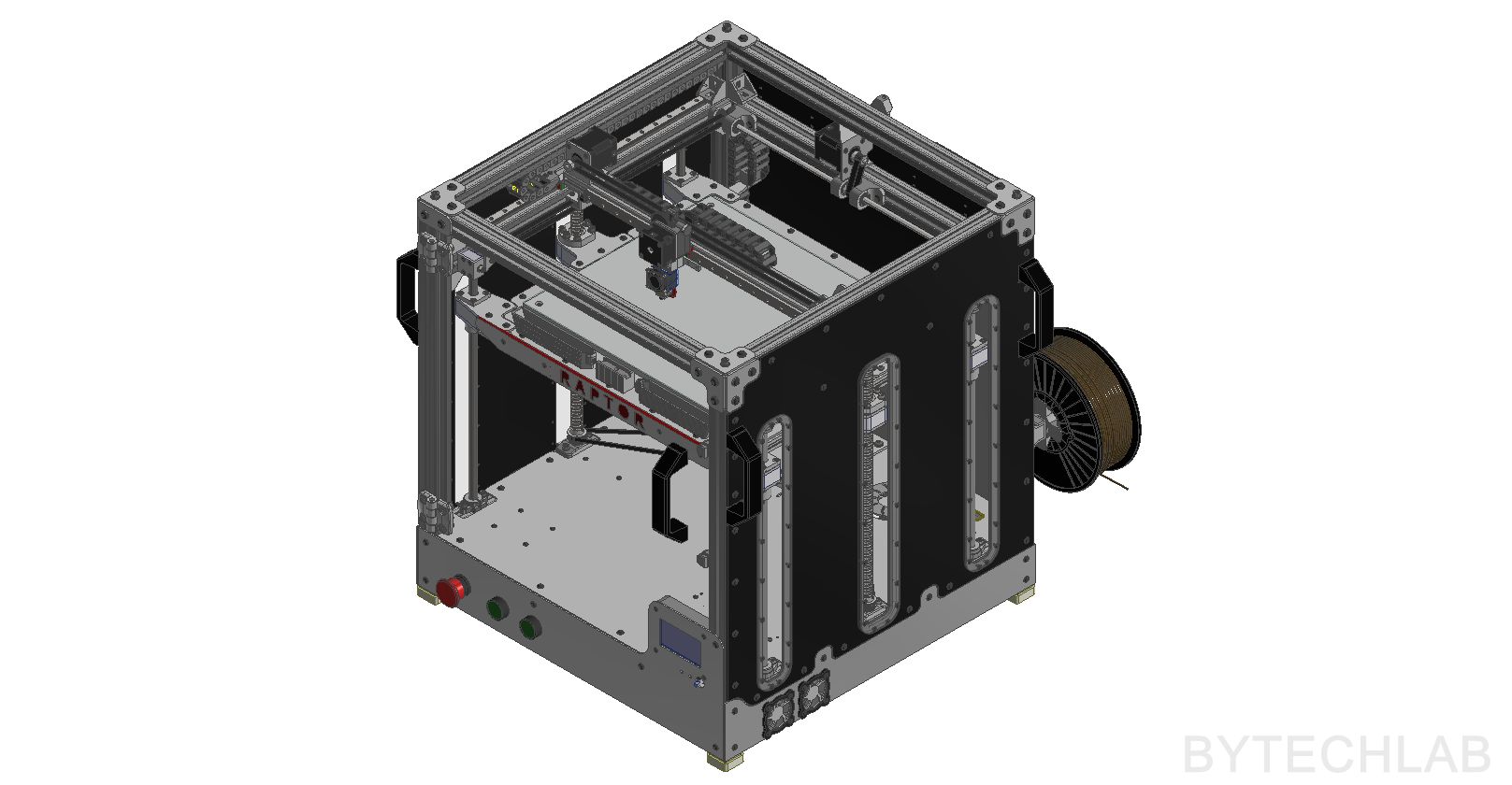
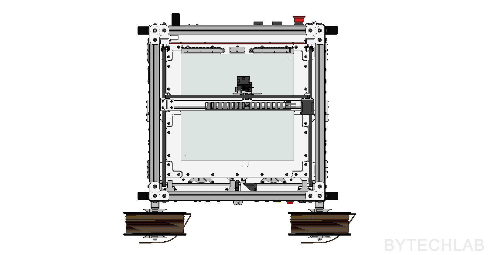
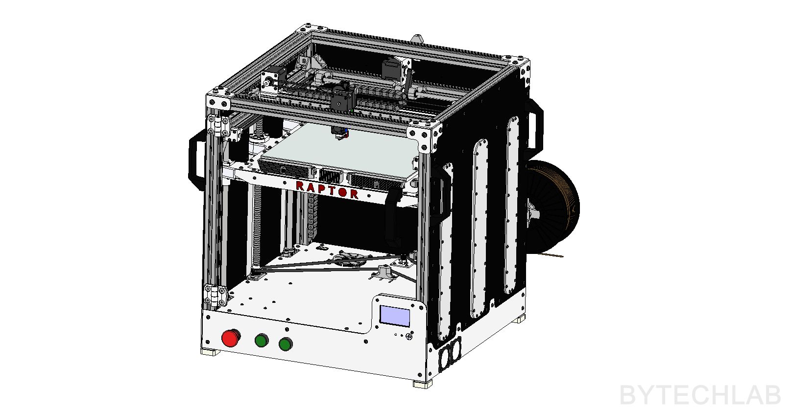
Below you can find some renders of the MCAD design:
HEATBED
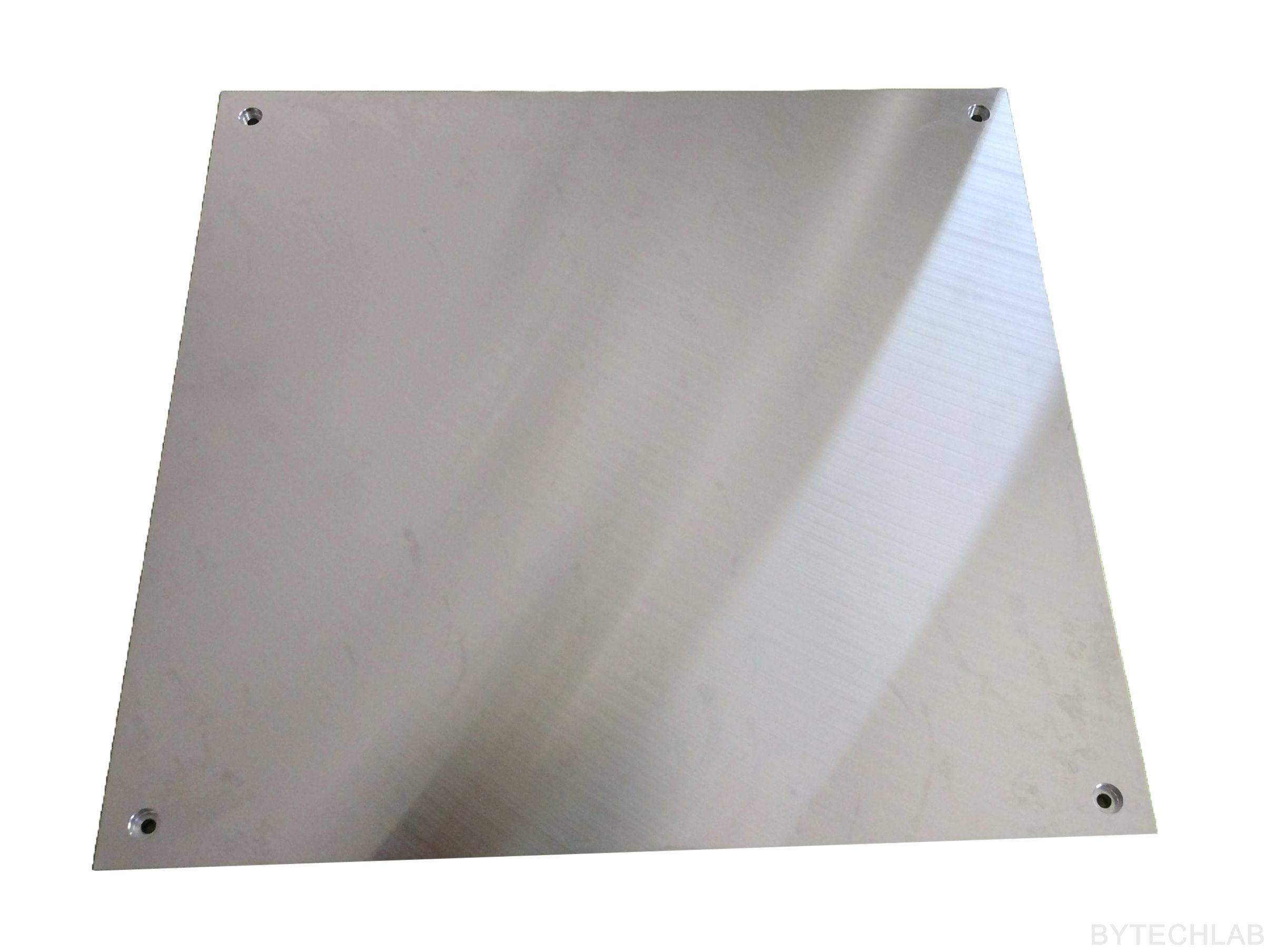
Heatbed was CNC machined from a high flatness aluminum plate (8 mm thick). It may look like a total “overkill” but in reality it’s not. Heatbed is incredibly flat. In order to prevent stress or bending during heating, heatbed is mounted to the Z axis platform in the way that it can expand freely. I am very happy with this heatbed – the distance between heatbed and the nozzle was adjusted only once after the printer was assembled. To this day everything is nicely leveled on the entire surface. The printer is free from auto leveling or other “gadgets” that hide the real problem.
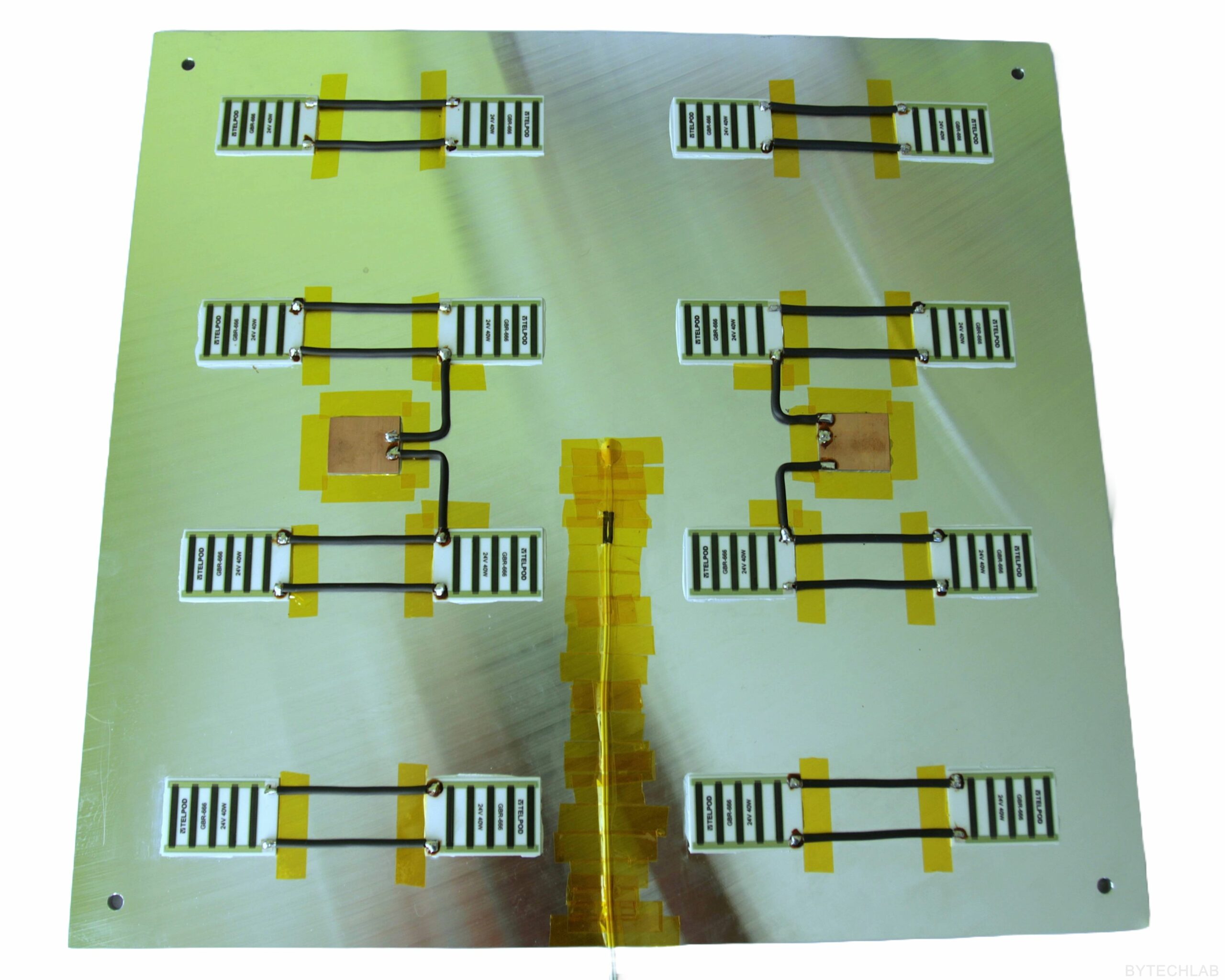
For heating the bed I have used 16x GBR-666 ceramic heating/power resistors (40 W each). When all of these ceramic resistors are connected together they draw about 620-640W of power (26A @ 24V). The resistors are connected in parallel and glued to the table with use of a high temperature thermal glue. The power is supplied to the table with thick copper wires (with silicone based insulation).
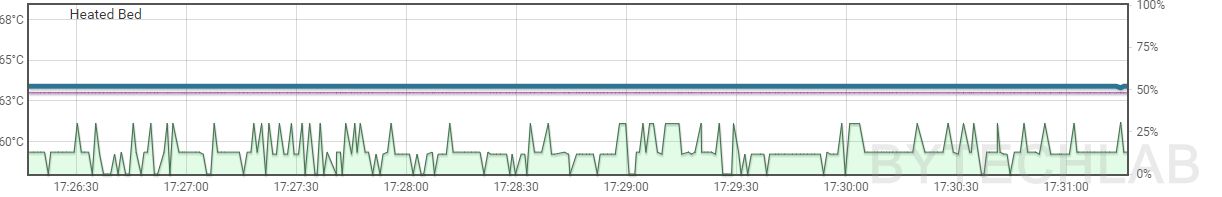
The thermistor, like the resistors, has been attached to the table with thermally conductive glue. I had to apply solder to these resistors before gluing them to the heatbed (thick aluminium plate would sink all the heat from the soldering iron due to high thermal capacity and prevent me from successfully soldering the wires). In addition, all wires are protected and insulated with a Kapton tape. With a slightly reduced power (I don’t want to heat it too quickly) heatbed heats up to 100 degrees in about 2-3 minutes. I have attached a 2 mm thick float-glass to the top of it (I don’t want to destroy such a beautiful shiny surface). Thanks to high thermal capacity of this heatbed after reaching the temperature set point, the temperature is very stable (below you can see temperature-stability chart).
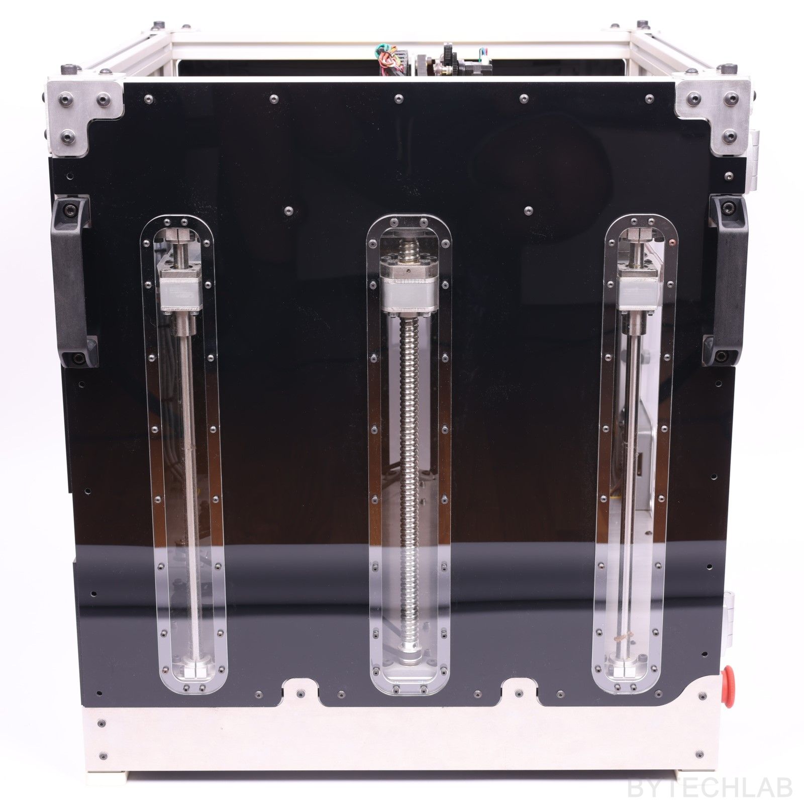
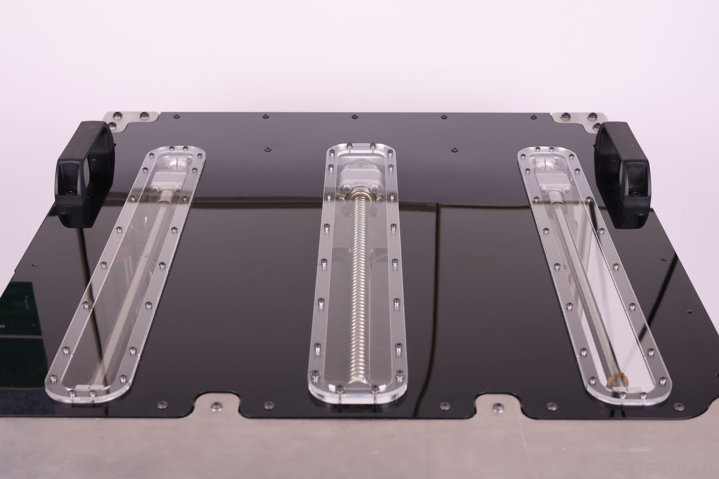
Z AXIS PLATFORM
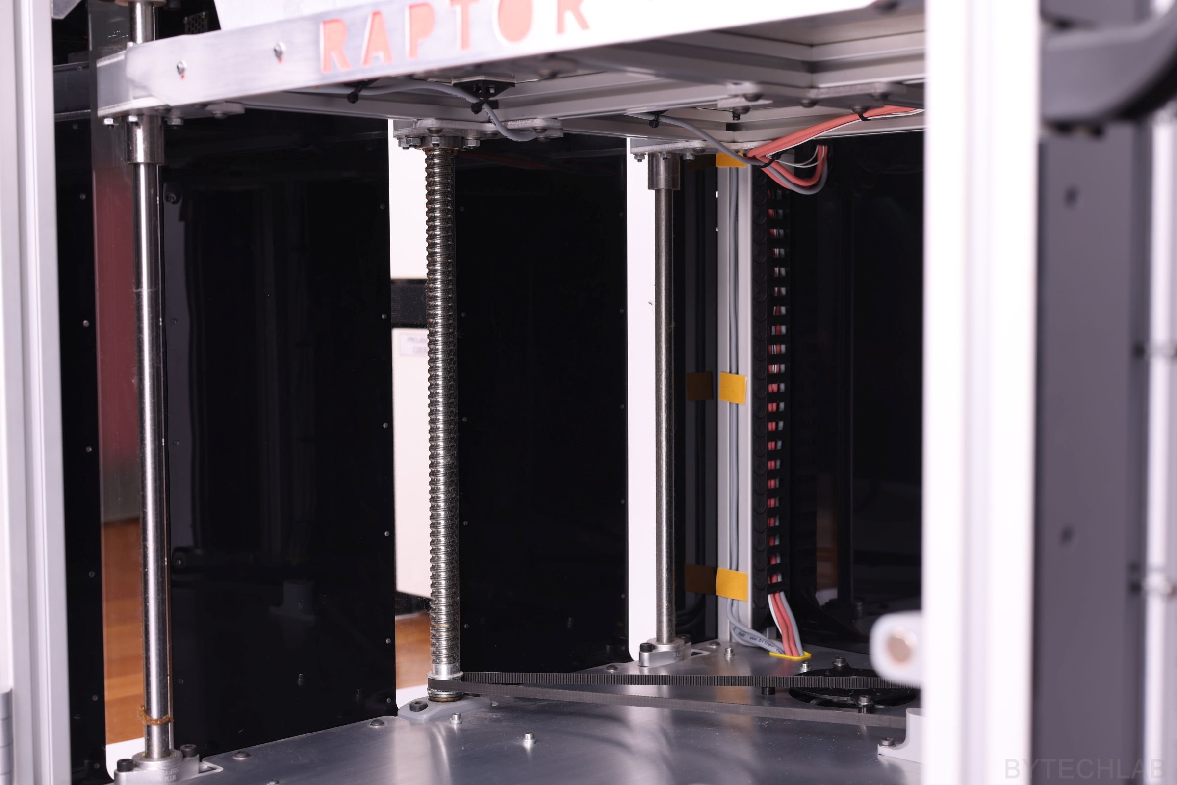
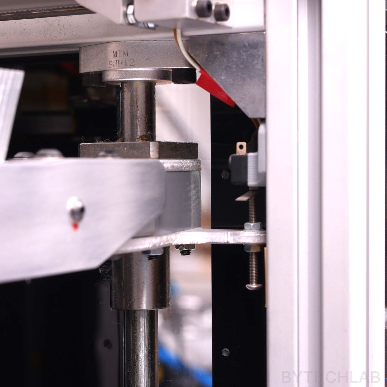
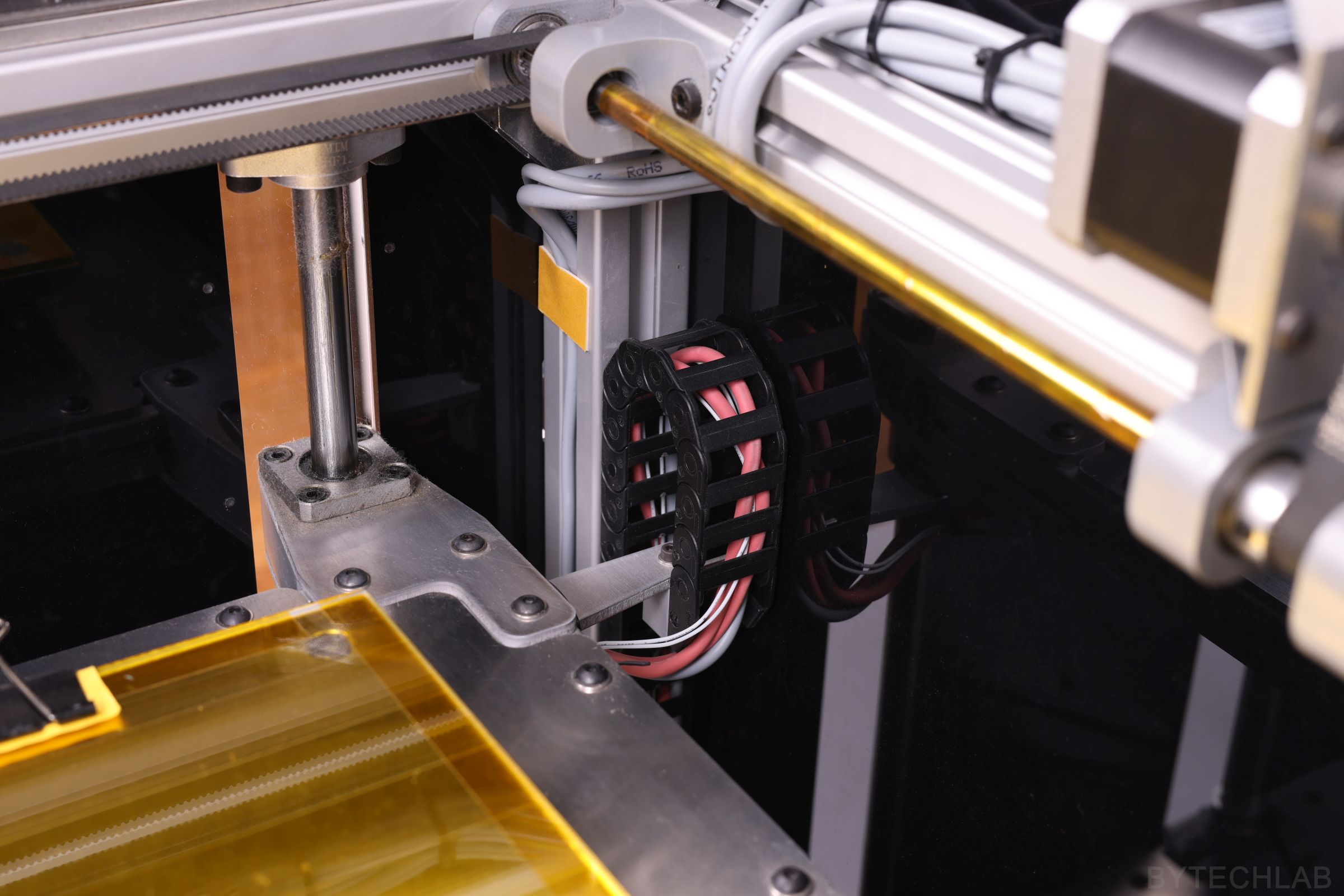
Because of size of this printer, the Z-axis platform is quite complex. In order to achieve the maximum rigidity of the entire system, I used two 1605 ball screws on both sides of the platform. On the corners of the Z axis platform I’ve installed LMK12LUU extended linear bearings that fit 12mm diameter linear rods. I didn’t wanted to use trapezoidal screws because they are usually bent and they would wear-out quite fast with such an load. Therefore, I used 1605 ball screws mounted on both sides. This is not the cheapest solution but it is definitely worth the price – I don’t have any problems with the Z axis in this printer. The whole Z axis platform is almost bulletproof , it is 36 mm thick in some places .
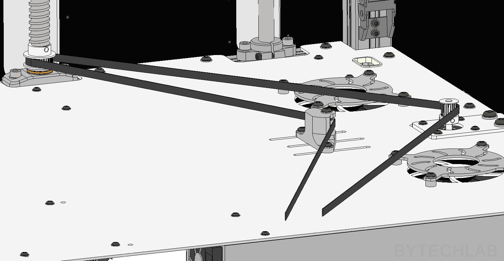
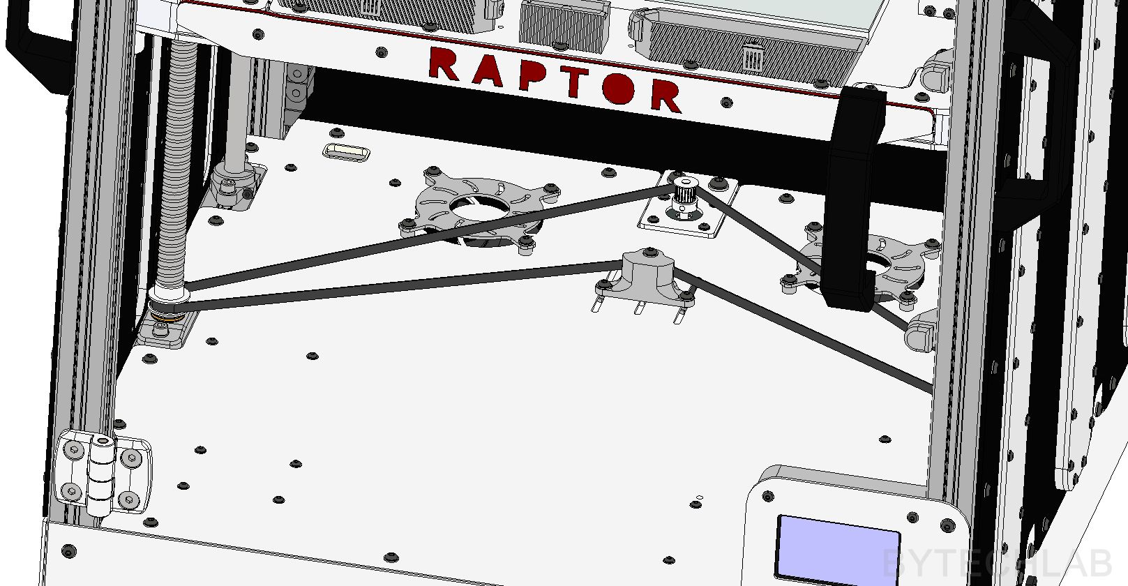
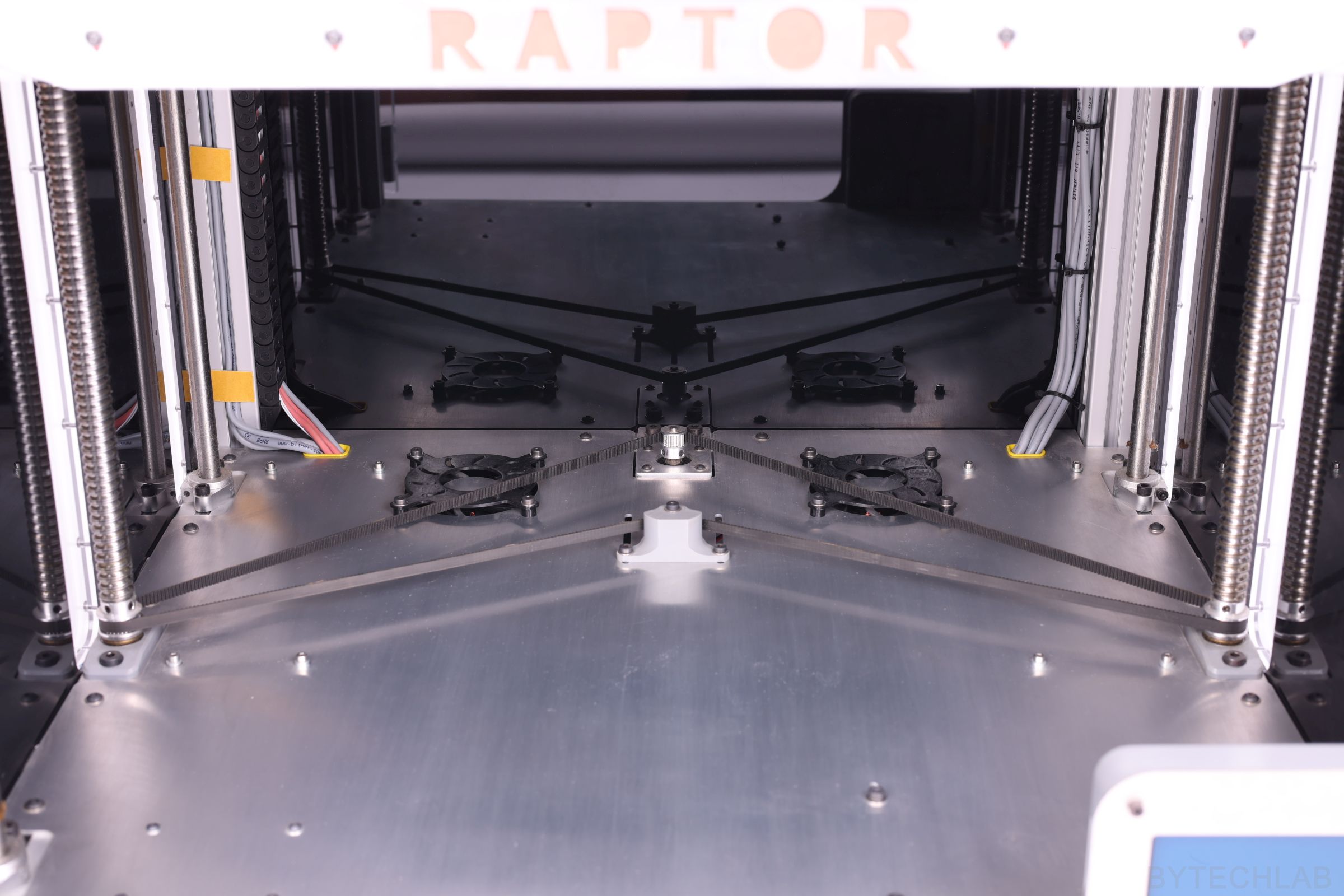
In addition, I have fixed the problem of Z axis lead screw “de-synchronization” by using an closed-loop GT2 timing belt that links everything together nicely. Z-axis ball screws have 40 teeth pulley’s on their bottom ends , and a 20 teeth pulley is mounted on the Z axis stepper motor which is located in the middle of the bottom plate. Because of this there is an small “gearbox” (1: 2 gear ratio) which allows me to obtain a higher torque on the ball screws that are quite hard to rotate (they support large weight of the whole z axis platform). The belt “tensioning” block consists of standard flanged ball bearings with a bolt passing through them. The entire part is attached to the bottom plate with 3 bolts that pass through the slots that allow you to adjust the belt tension.
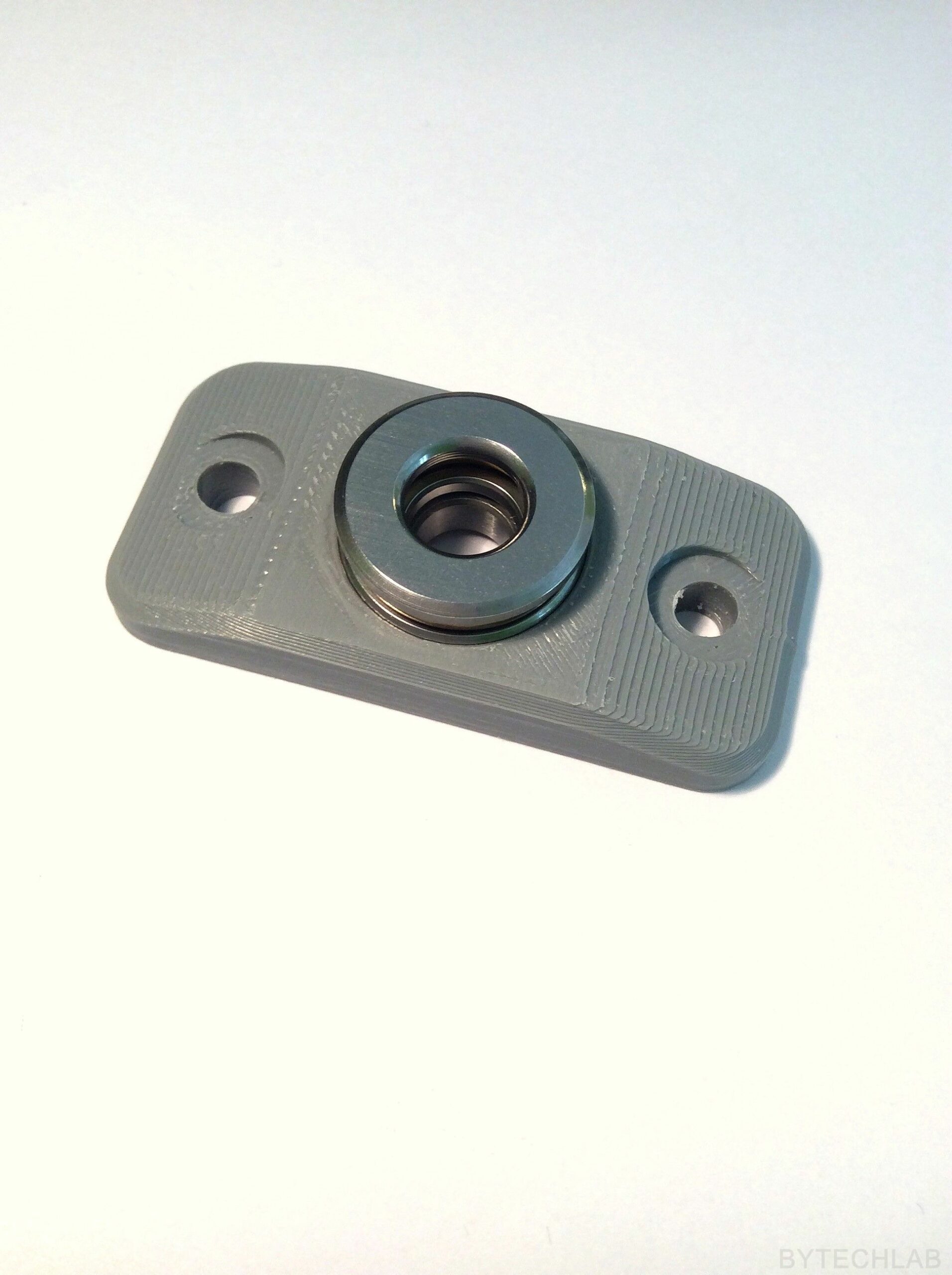
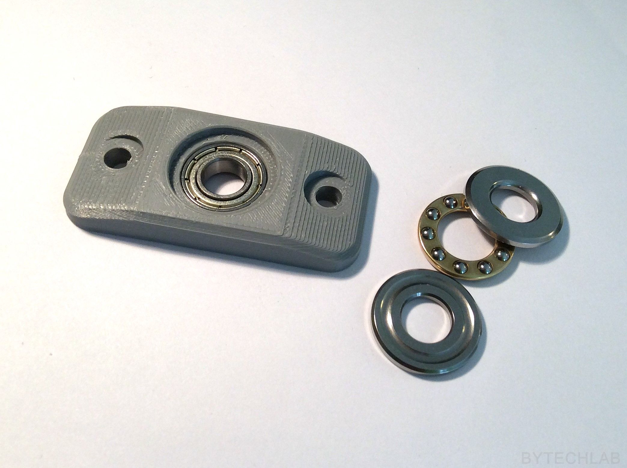
In the beginning, I have used ordinary ball bearings to support the ball screws. As it soon turned out, they couldn’t survive such a high axial load. As there was no space for a standard bearing block, I had to design my own which works just as well. It consists of a thrust bearing and an ordinary ball bearing. The thrust bearing transfers axial loads directly to the frame and the ball bearing prevents the ball screw from moving sideways. The bearing block is printed from ABS, with 100% infill.
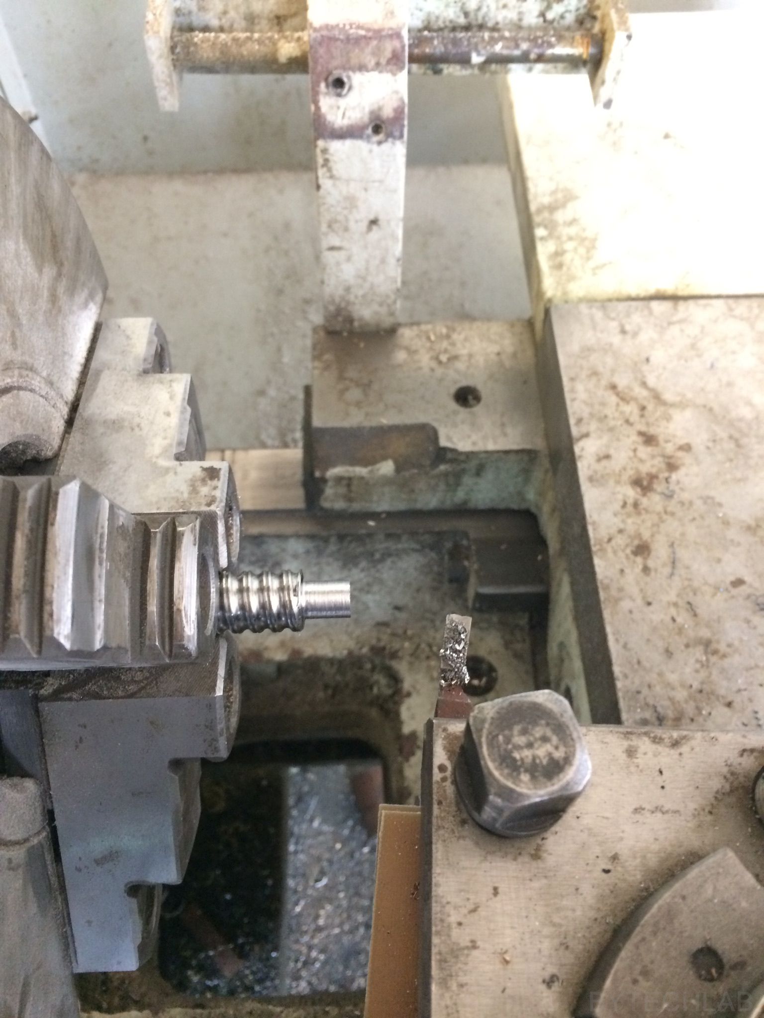
As the ball screws had ends that were too large in diameter, I had to machine them on the lathe to make them fit to the ball bearings. It wasn’t simple because it’s a surface hardened screw. Firstly I had to machine the top layer with a carbide insert and then everything was going smoothly.
I started assembling the Z-axis platform by attaching the 20 x 20 mm aluminium profiles to the 4 mm thick aluminium plate with use of many screws. In addition, on the bottom I have mounted aluminum brackets that make the entire platform more rigid. All linear bearings and ball nuts are attached to the platform with a mounting brackets that look like an sandwich. These mounting brackets are made of 3 parts: 4 mm thick aluminum sheet on top and bottom with an solid 3D printed ABS fillers between them. Because of this, it is possible to significantly increase the rigidity of the whole Z-axis assembly. Unfortunately, it wasn’t possible to design it in the way that the linear shafts and bearing blocks wouldn’t stick out from the frame contour. It is only a millimeter or two, but because of this it was impossible to attach the side Plexiglas panels to the frame. I solved this problem in a quite interesting way about which I will write later in this article.
The whole Z-axis platform is very rigid. There is no chance to bend it with your hand. Due to its mass and inertia, it doesn’t vibrate at all. Vibrations on the Z-axis platform could potentially cause many defects on the 3D prints. Accuracy and repeatability of movement of the whole system is very good – I have made multiple tests with an dial indicator. Ball screws driven by a single belt are excellent – I will never use two or more stepper motors in this axis.
X AND Y AXIS
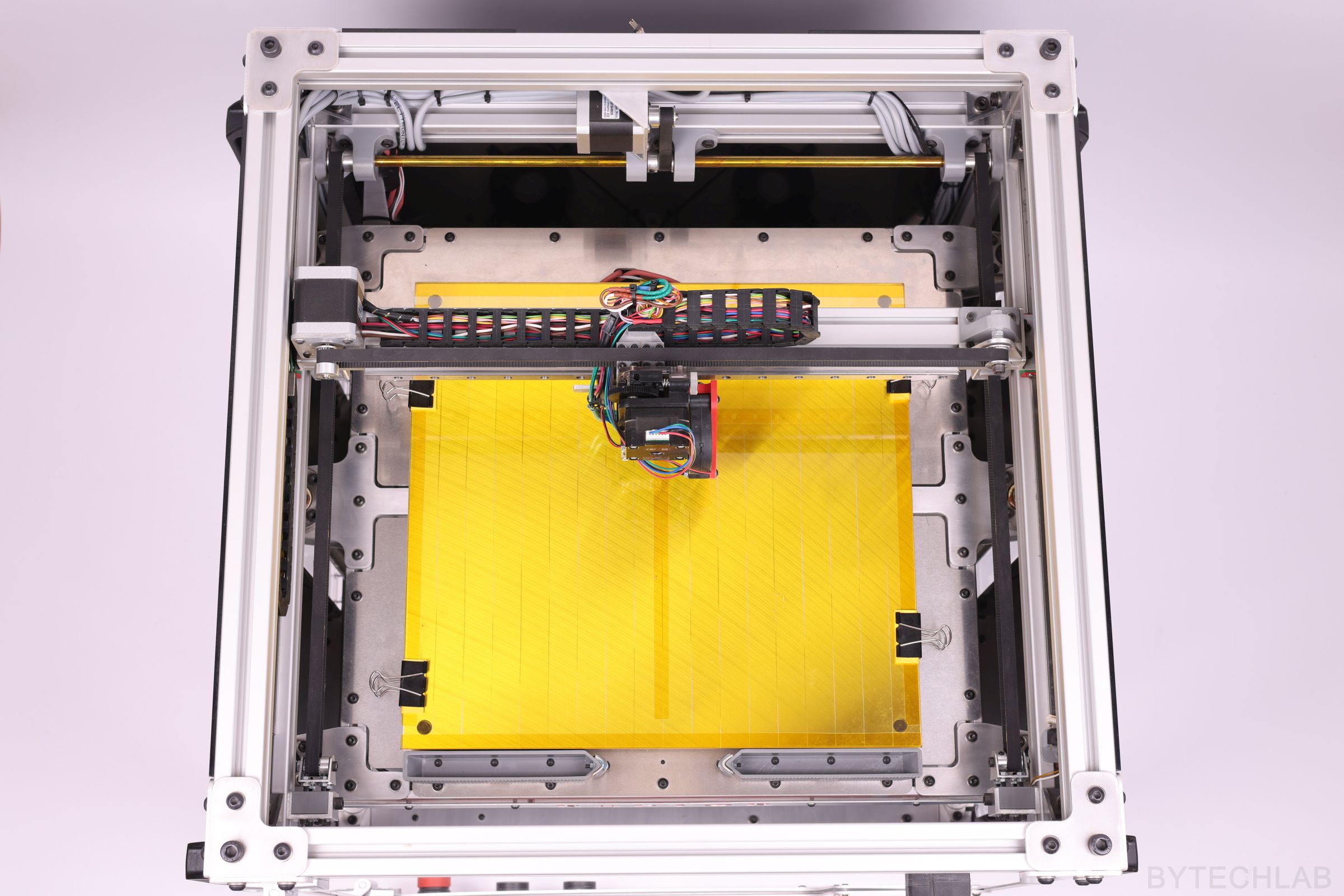
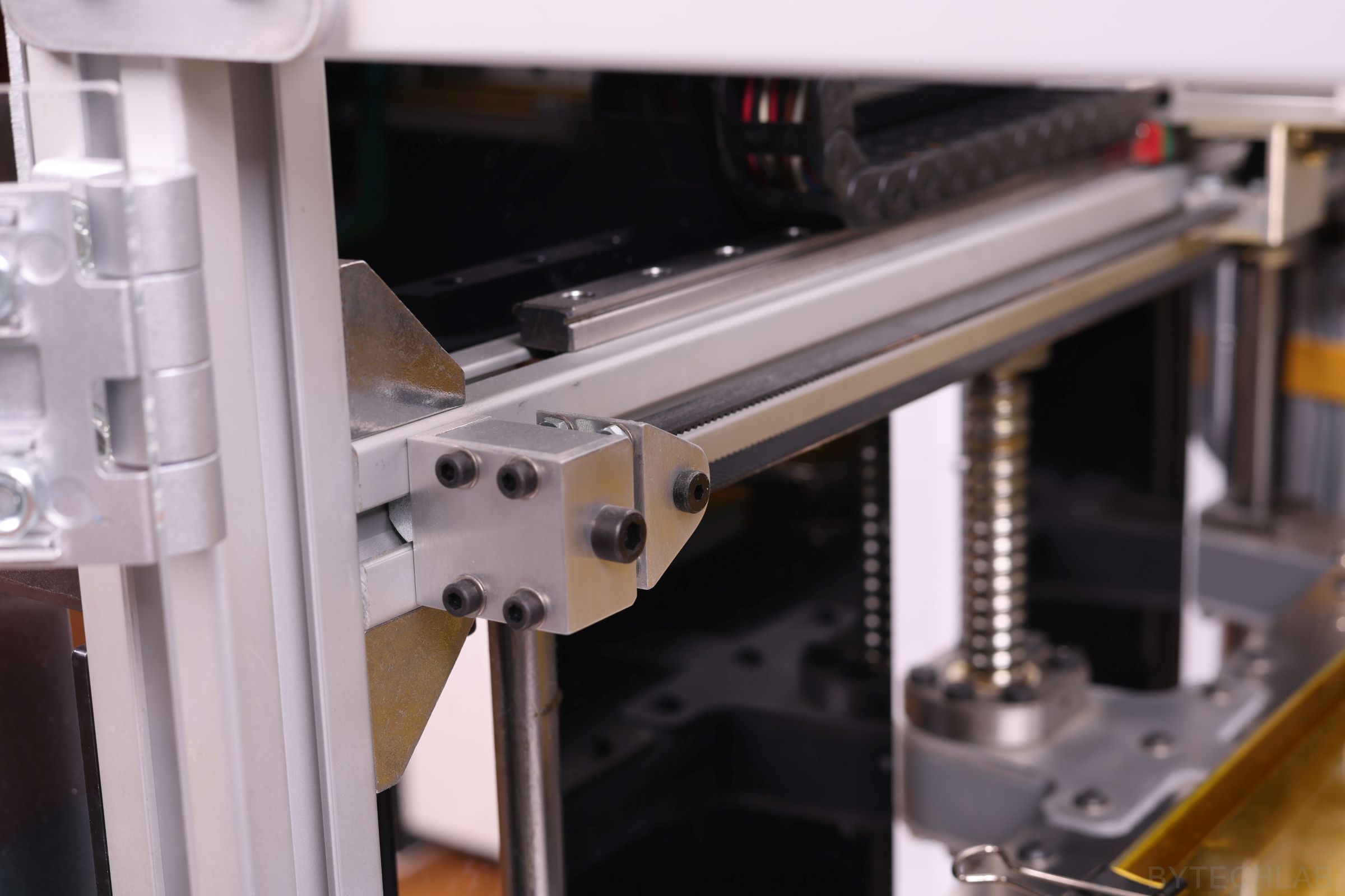
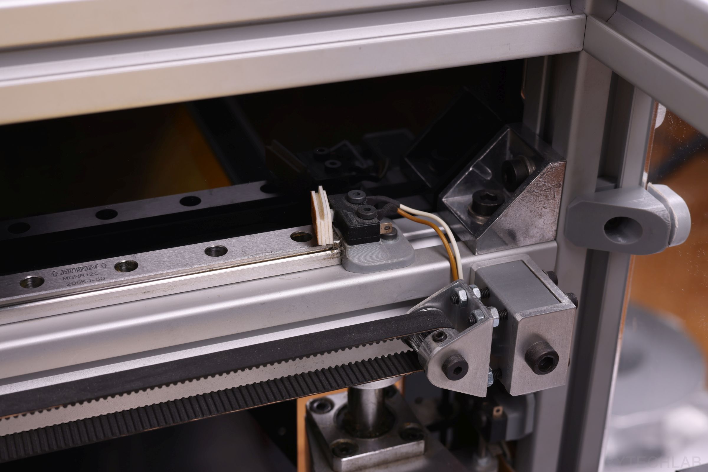
When I was designing this printer, I decided to implement a simple cartesian-type kinematics with use of “bullet proof” mechanical components. In both axes, I used the genuine HIWIN MGNR12 linear rails and HIWIN MGN12H bearing blocks. All linear rails are mounted to the printer frame with use of short M3 bolts and T slot nuts. I used some gauge blocks to align linear rails. The alignment of the whole X/Y kinematics took some time – I wanted to be sure that all of the dimensions are correct, so that later there wouldn’t be any problems with jamming of the bearing blocks.
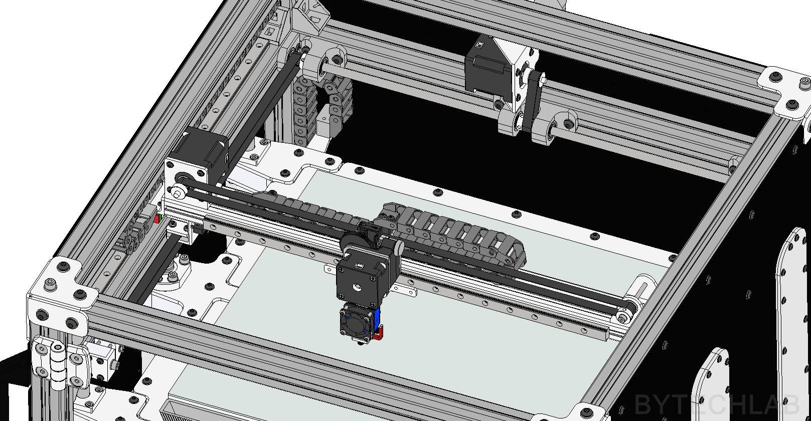
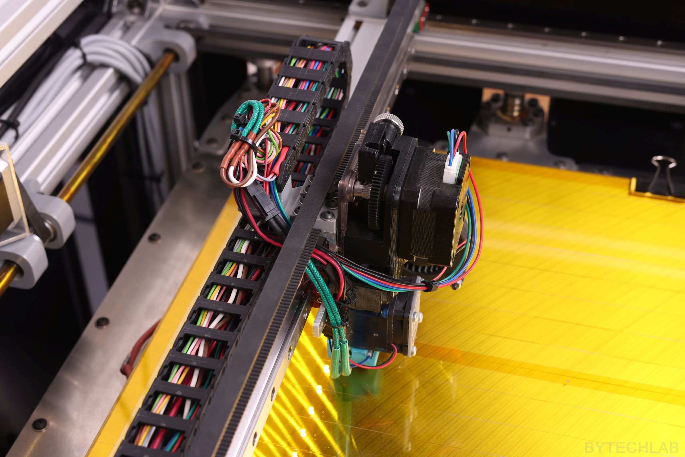
The entire X axis is based on the 20×40 aluminium extrusion profile. Stepper motor and belt idler mounting brackets were machined from an aluminum angle profile on a CNC milling machine. The end of the cable carrier from Igus has been attached to the X-axis carriage to improve overall appearance and to get rid of an “cable spaghetti”. In addition, I have attached aluminum plate with holes for additional accessories to the x-axis carriage .
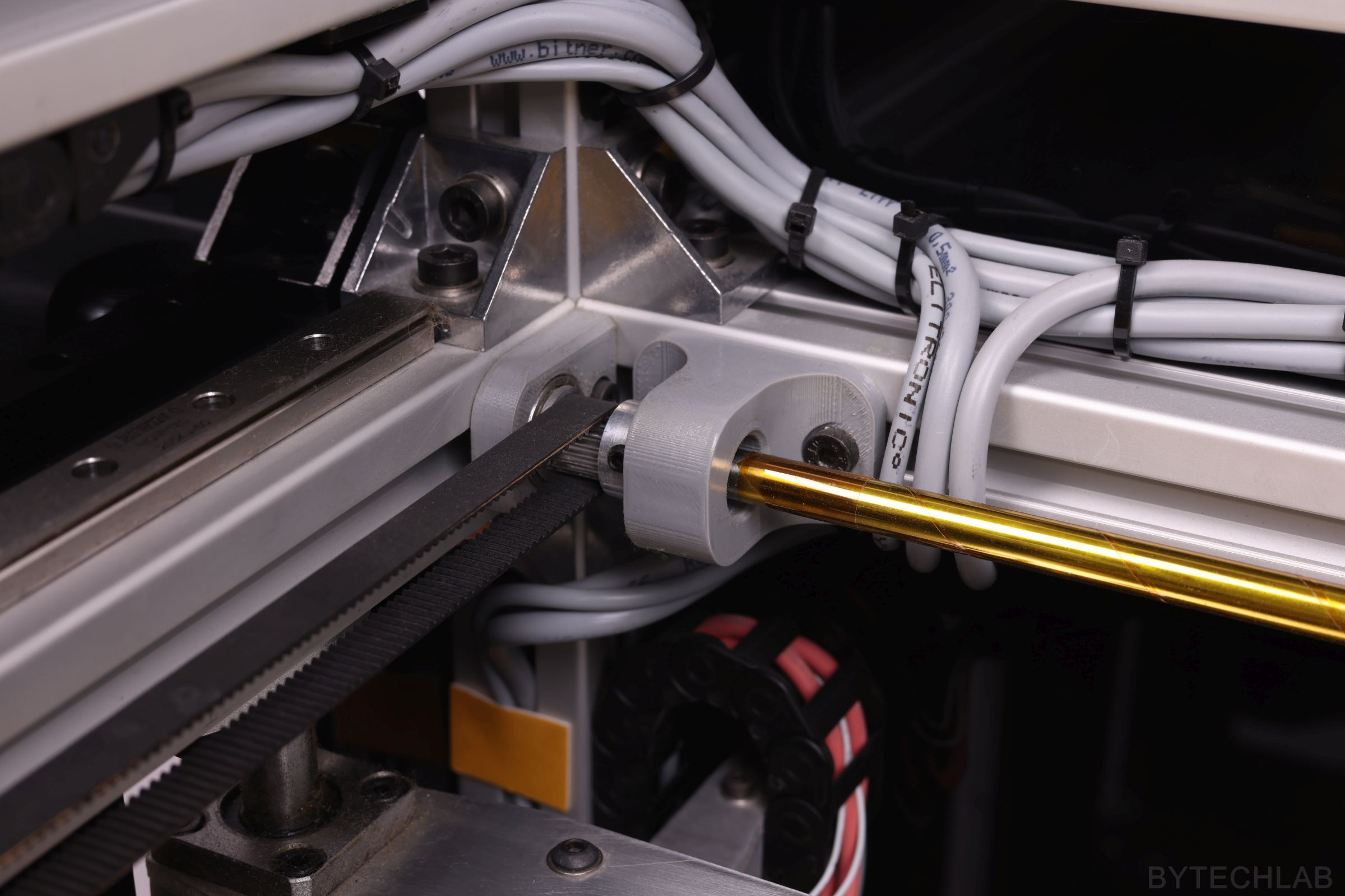
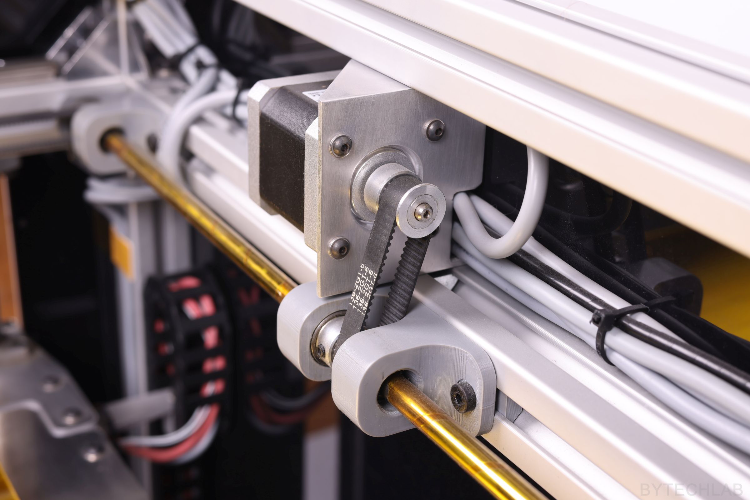
The Y-axis stepper motor is also attached to a aluminum profile that has been machined on CNC. Of course, all the mounting holes are in “slot shape” so that the belt can be easily tensioned. The stepper motor rotation is transmitted through a closed loop timing belt to a steel shaft (8mm diameter). The shaft drives both sides of the X axis evenly from both ends – because of that there are no problems with uneven distribution of forces. The shaft is attached to the frame with 3 bearing blocks. There are two ball bearings inside each one.
All timing belts are 9 mm wide (GT2 type). The Y-axis belts go through the pulley’s on the pulley shaft and the idler on the other side. The tensioning mechanism was made of c-section aluminum profile and GT2 pulley’s with 4 small bearings inside. The belt is attached to the Y axis with an c-section aluminum profile (3 mm thick). Belt is attached to this aluminium profile with two 3D printed clamps that firmly hold it in place from both sides.
In the Y-axis, I have also used Igus cable carrier, it allows me to hide all wires nicely. All necessary parts have also been cut out of aluminum sheet. The X-axis beam has been attached to the Y-axis carriages with CNC milled aluminium angles.
ELECTRONICS
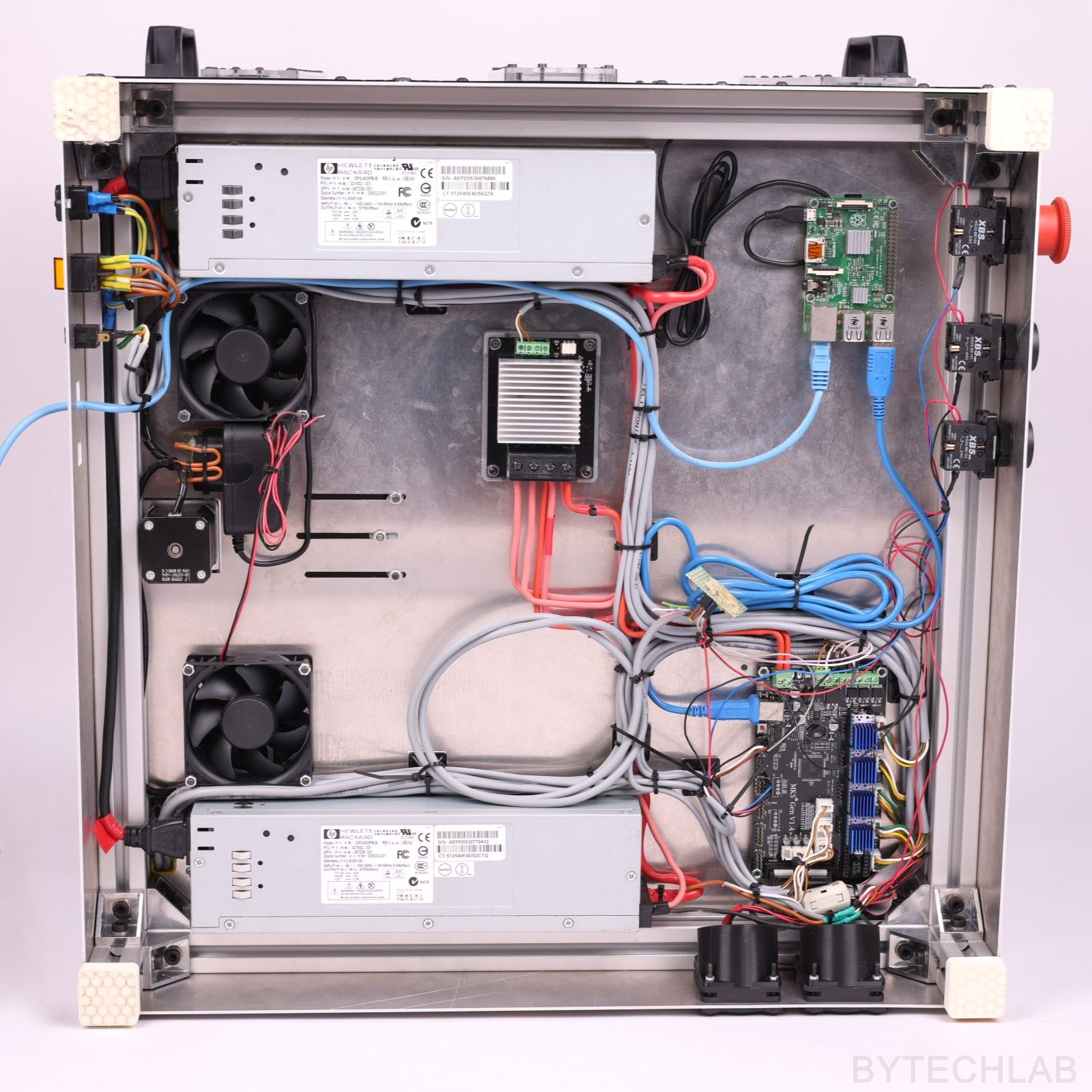
I’ve used two HP DPS-600PB server power supplies to provide the 24V power supply rail. They are connected in series with thick copper wires after previous internal modifications. I want to say right away that these power supplies are quiet (much quieter than the original fan supplied with the hotend from E3D). There is one pin which makes it possible to easily reduce the fan speed by shorting it to ground. Without modification, the connection of such power supplies may result in a fire (You are creating an ground loop) therefore I don’t recommend such modification to inexperienced people !.
I’ve used the MKS Mosfet module to switch the heatbed current. As a 3D printer controller I have used “MKS Gen 1.4” (based on Atmega 2560 MCU). As a print server I have used Raspberry Pi 2 with a Wi-Fi module. The Raspberry Pi is running the Repetier Server software.
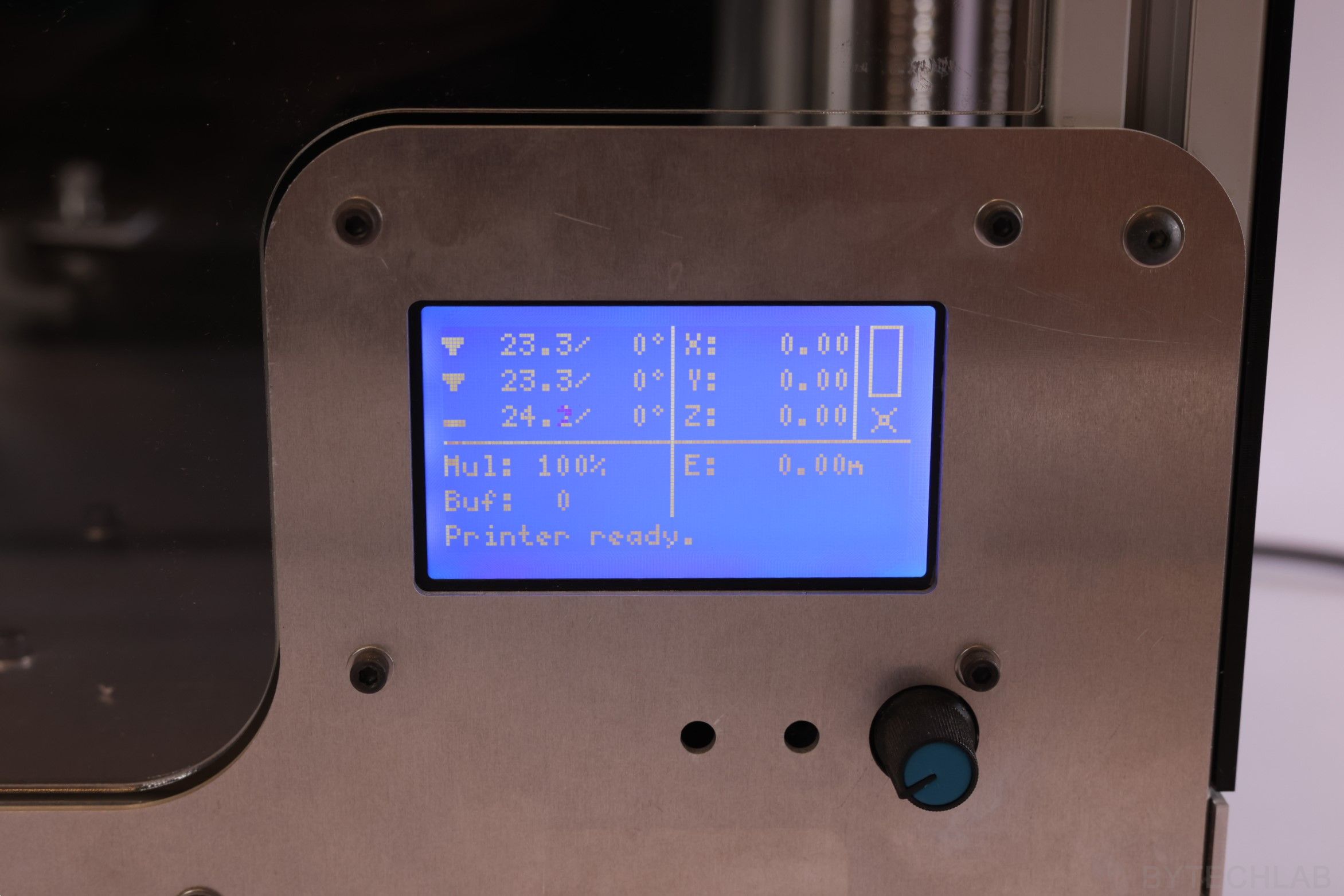
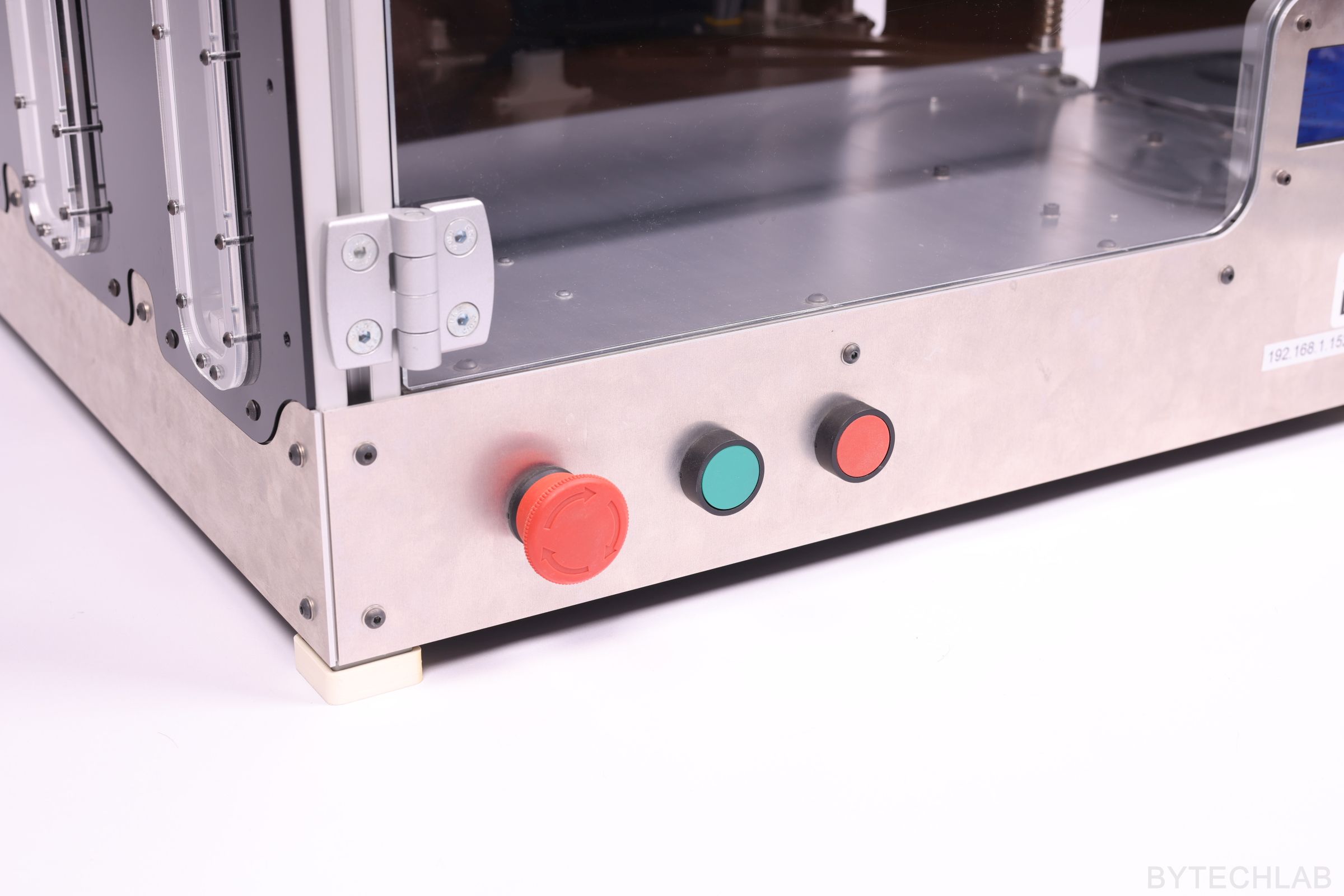
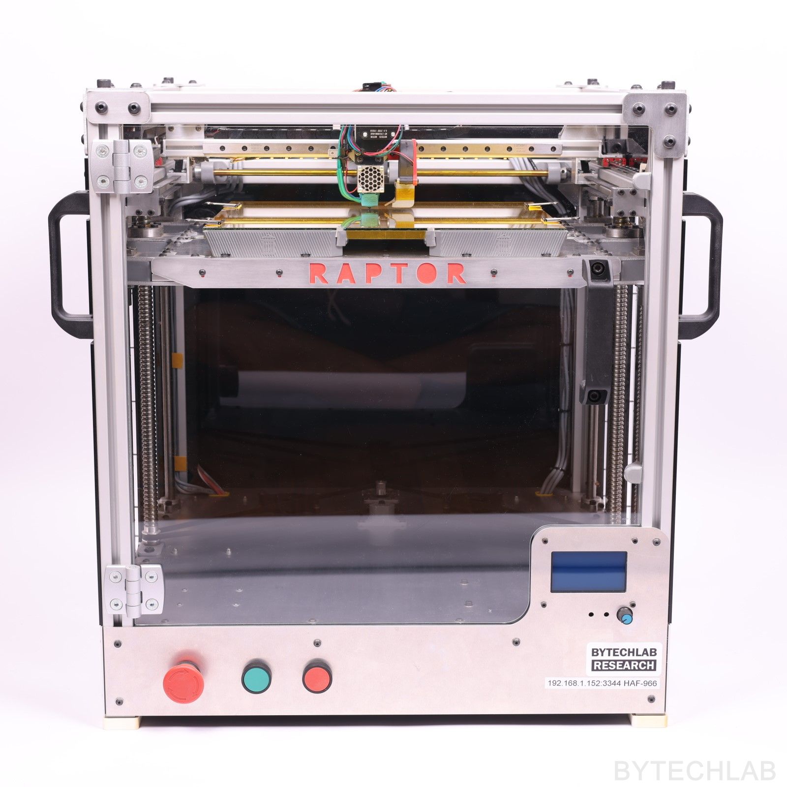
On the front I have mounted a graphic LCD display with an encoder and SD card slot (“RepRapDiscount Full Graphic Smart Controller”). The wires from the display required a ferrite bead in order to suppress interference from stepper motors cables. Additionally, I have attached nice big industrial buttons to front panel:
- Emergency switch to shutdown the printer,
- Red button to pause printing,
- Green button to resume printing
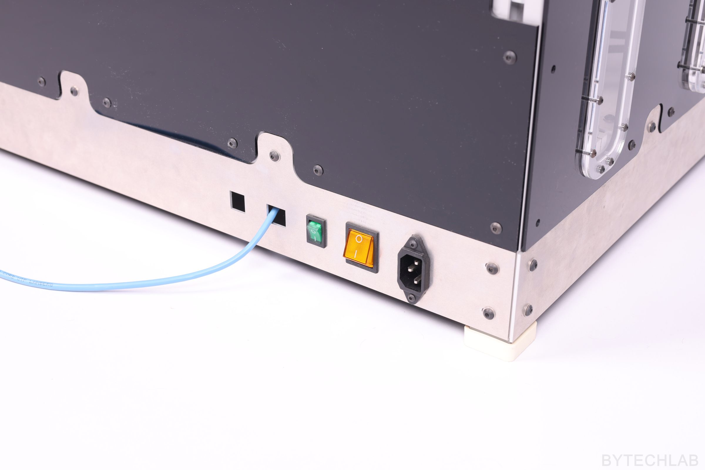
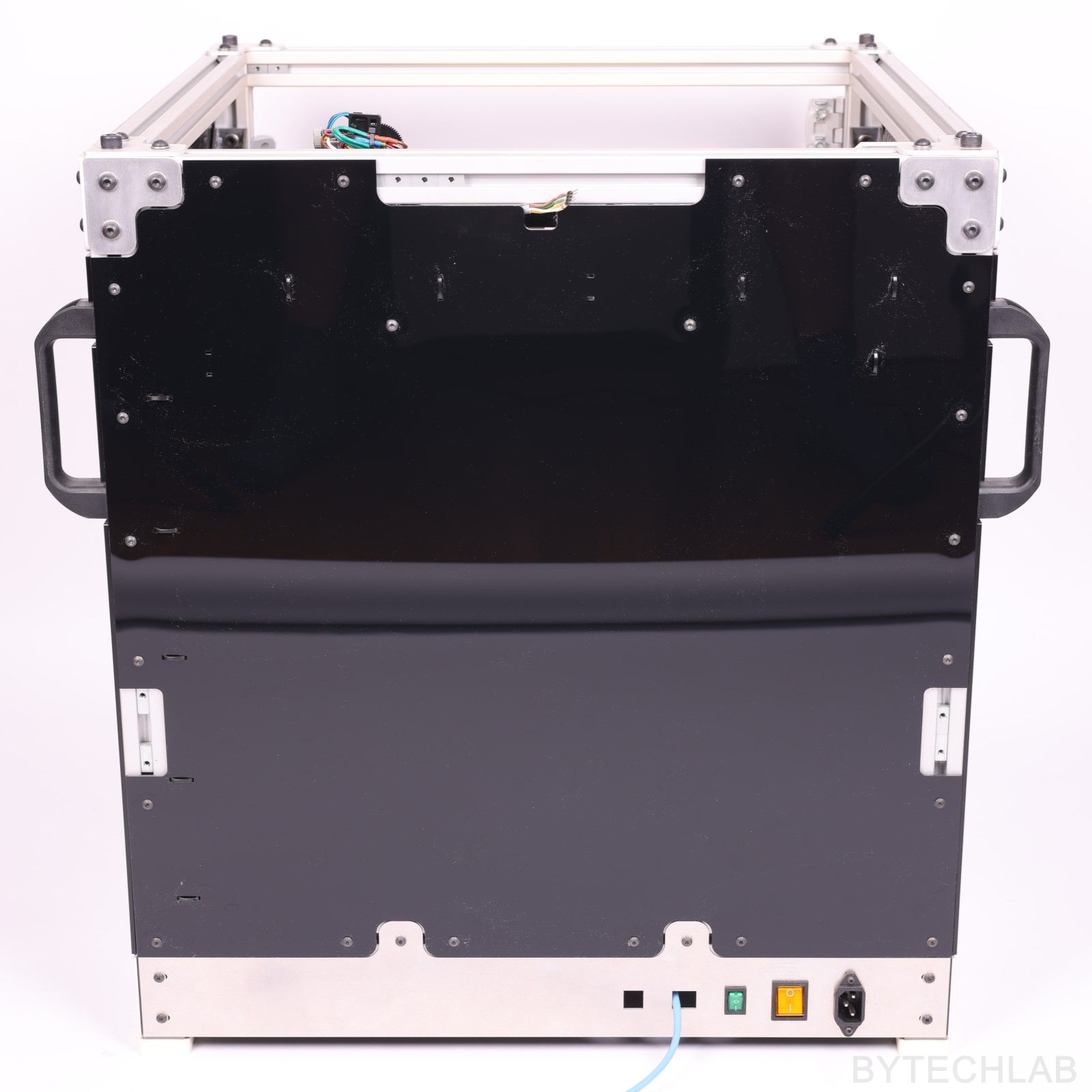
I’ve also designed a nice panel on the back of the printer with integrated switches for turning led’s and power supply on and off. There is also mains power connector of course.
SEMI-CLOSED CHAMBER
The main chamber was closed with use of 3 mm thick black plexi panels that were cut with a laser. Only the front door is made of transparent plexi that is 4 mm thick. I’ve solved the problem of sticking out Z-axis platform mounting brackets by making windows in the side panels. These windows are closed with transparent plexi panels that have some plexi spacers under them. They look quite nice when I turn on the LED strips inside the chamber – they just look like portholes on the ships.
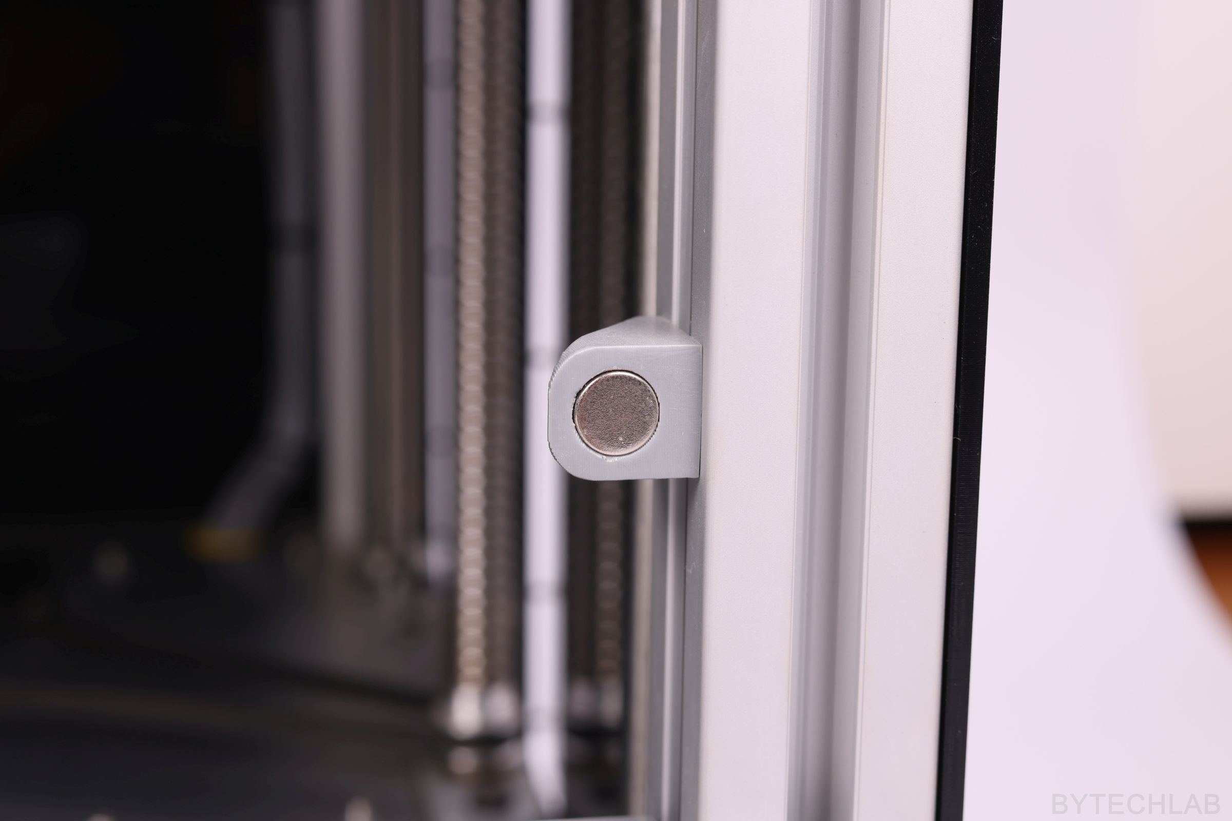
I have added neodymium magnets to the front door and the frame. Because of that this door will be closing by itself every time you open it. The handles have been mounted to the frame on each corner to allow me to move this heavy monster to a different place.
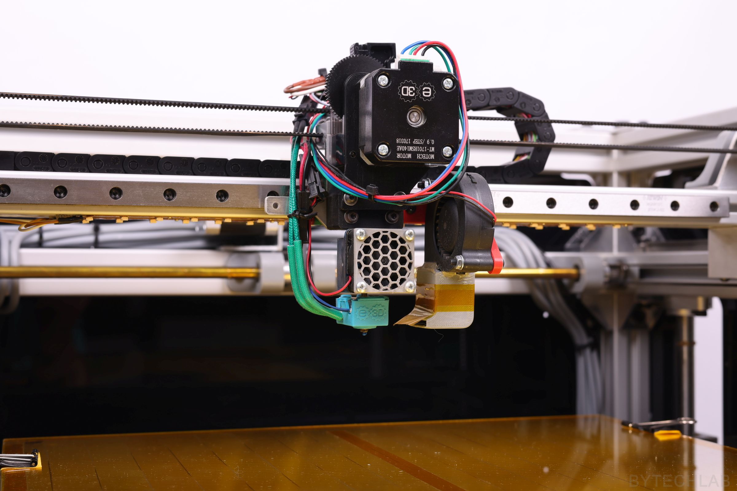
EXTRUDER AND HOTEND
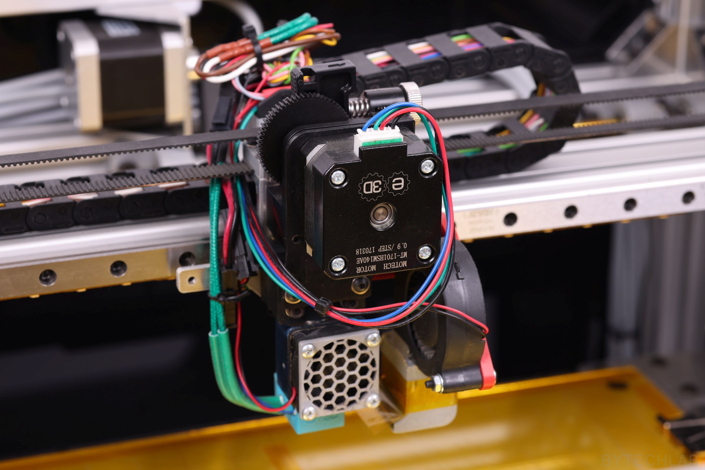
As an extruder, I have used new Titan together with V6 hotend from E3D. I have also used a hotend silicone sock from E3D that protects the hotend from melted filament and isolates it from the surrounding environment. A pancake motor (Nema 17 ,400 steps per revolution) is installed on the extruder in order to eliminate the effect of uneven extrusion caused by skipping the microsteps.
LIGHTING AND ENDSTOPS
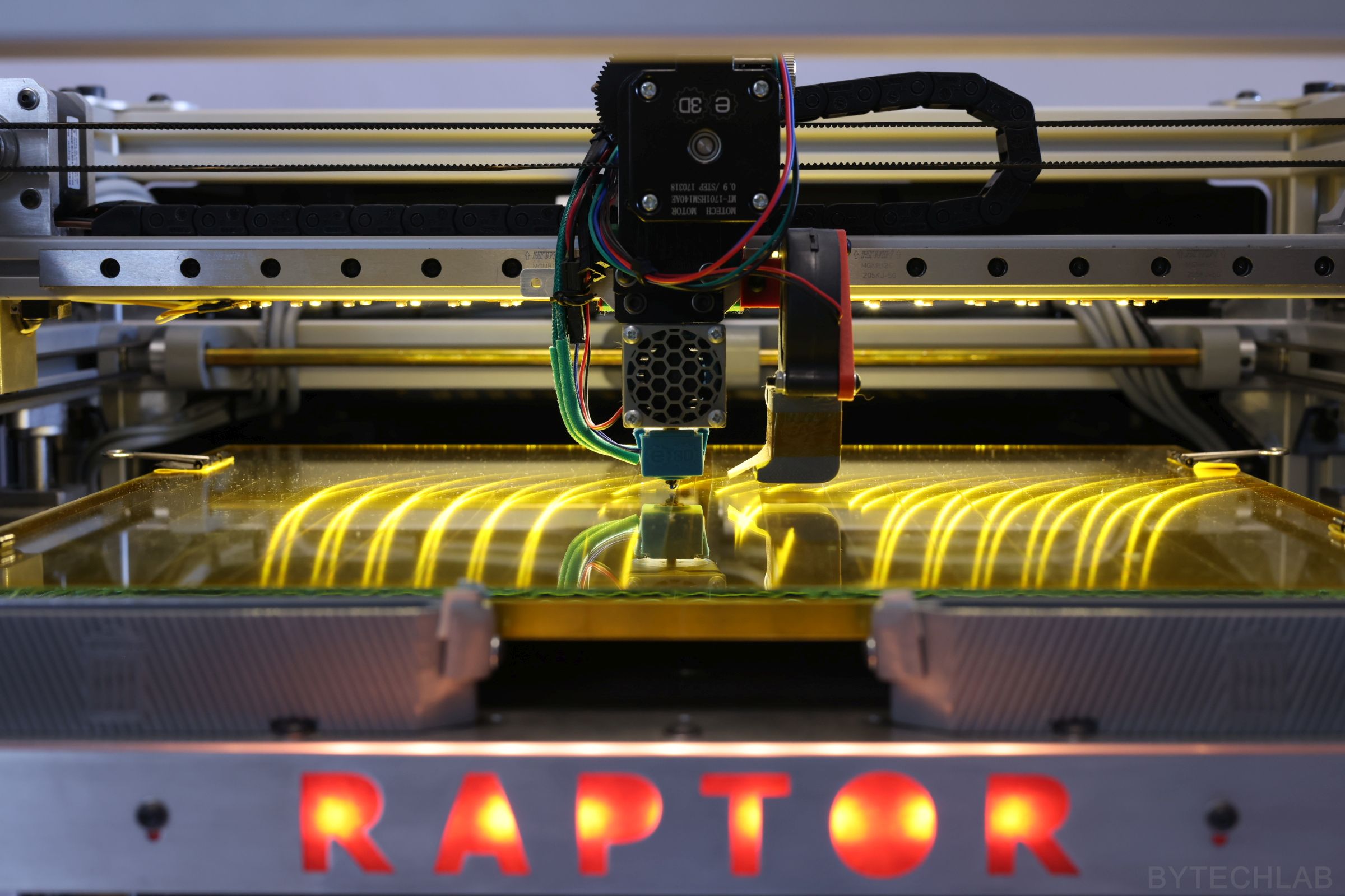
After installing 2 LED strips under the X-axis beam, I found that I don’t need more LED strips to light everything up. In order to improve appearance of this printer I installed a neat laser cut aluminium panel with the printer name embedded into it. I have placed a matted plexi that diffuses light from a red LED strip under this panel. Unfortunately, I forgot to make small tabs that would hold internal parts of letters in place.
All endstops in this printer are quite standard – ordinary mechanical switches. Over Z axis endstop I have installed a screw that is used to change homing offset in this axis.
ADDITIONAL FEATURES
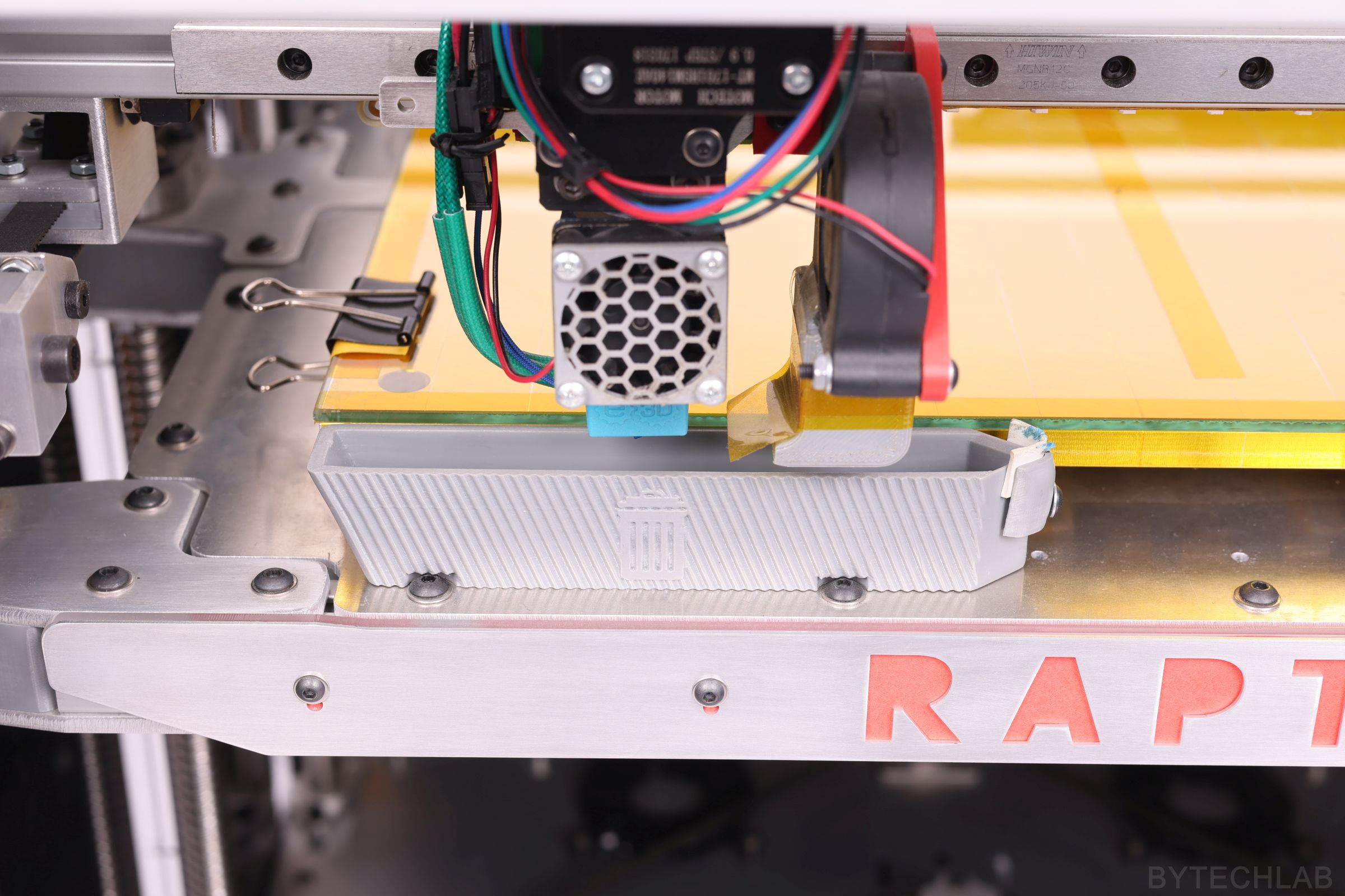
One of the additional features that are currently installed in the printer are small trash-bins. They allow to extrude out an old filament while warming up the hotend. The nozzle can be wiped out with a rubber band located at the end of the trash bin. Thanks to this, I don’t have to wait with tweezers until the printing process starts in order to remove any hanging filament residues from the nozzle. As you know, these melted filament pieces can seriously damage first layer.
FDM 3D PRINTER (RAPTOR-360) SPEC:
- Build volume [XYZ]: 360 x 360 x 360 mm,
- Printer weight ~ 30-40 Kg,
- External dimensions: ~ 58 x 58 x 63 cm,
- Power consumption 800-900 W peak,
- Two 1605 ball screws and four linear shafts Ø12 mm in the Z axis,
- Printing server: Raspberry pi 2 + Repetier + WiFi + Camera,
- Controller PCB: MKS Gen 1.4,
- Hotend: genuine E3D V6,
- Extruder: genuine E3D Titan,
- Genuine HIWIN linear rails and bearing blocks in X / Y axis,
- 400 step per revolution motors on all axes, including the extruder,
- Power supply with a total power of 1.2 kW @ 24V,
- Structural Z-axis platform (max. thickness ~ 28 mm),
- Semi-closed chamber,
- Frame made of 30 x 30 mm aluminium extrusion profiles, steel and aluminum,
- 9mm wide GT2 timing belts ,
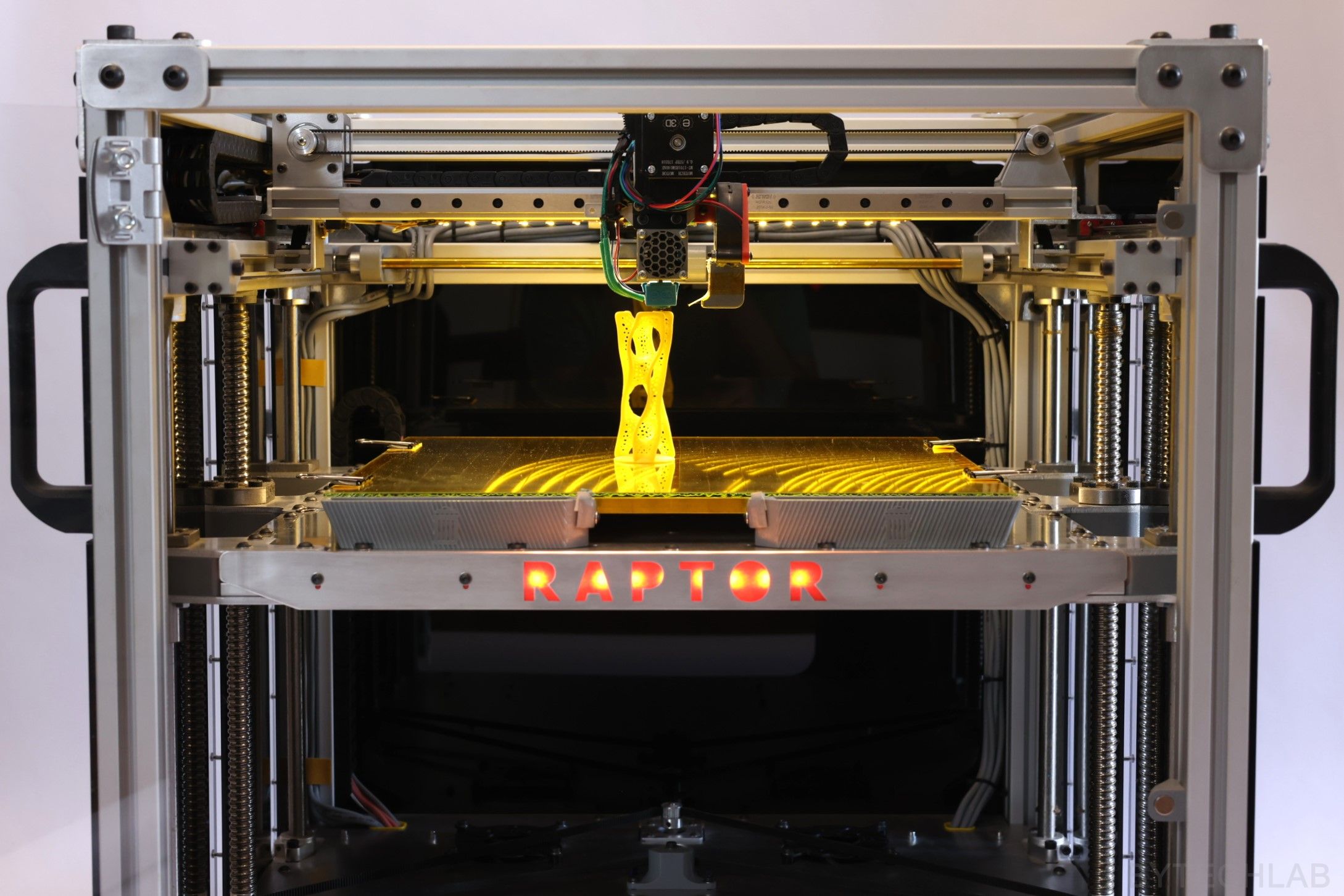
FINISHED PRINTER – PHOTOS
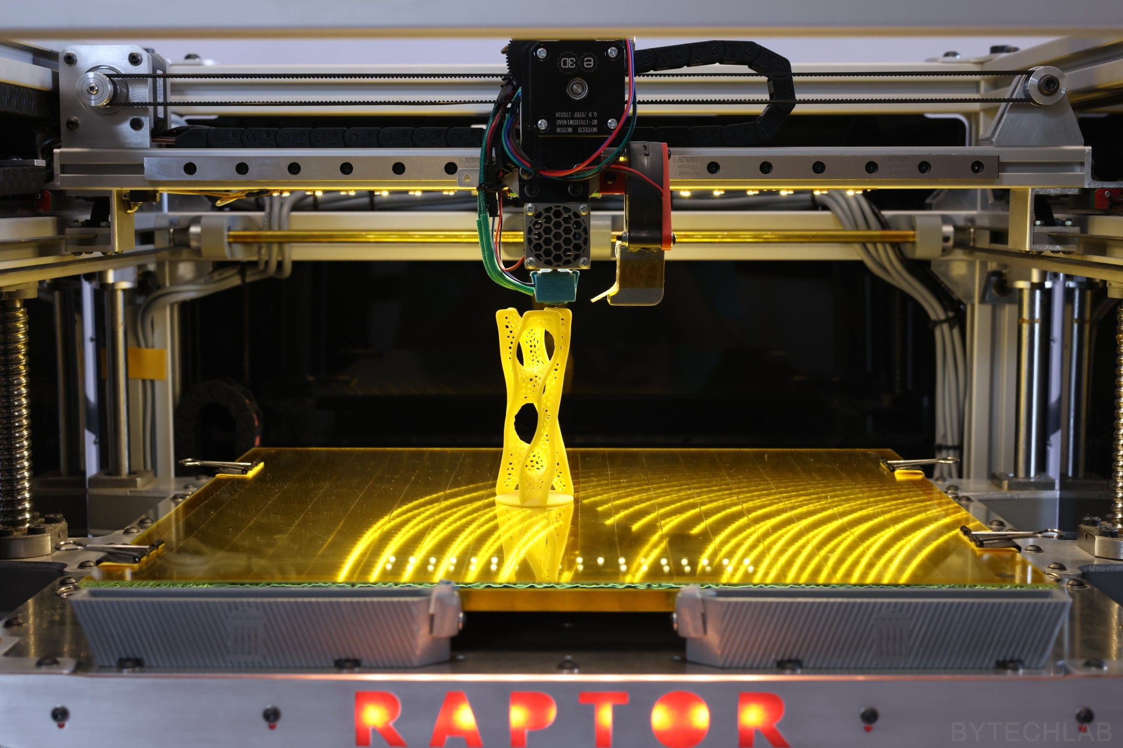
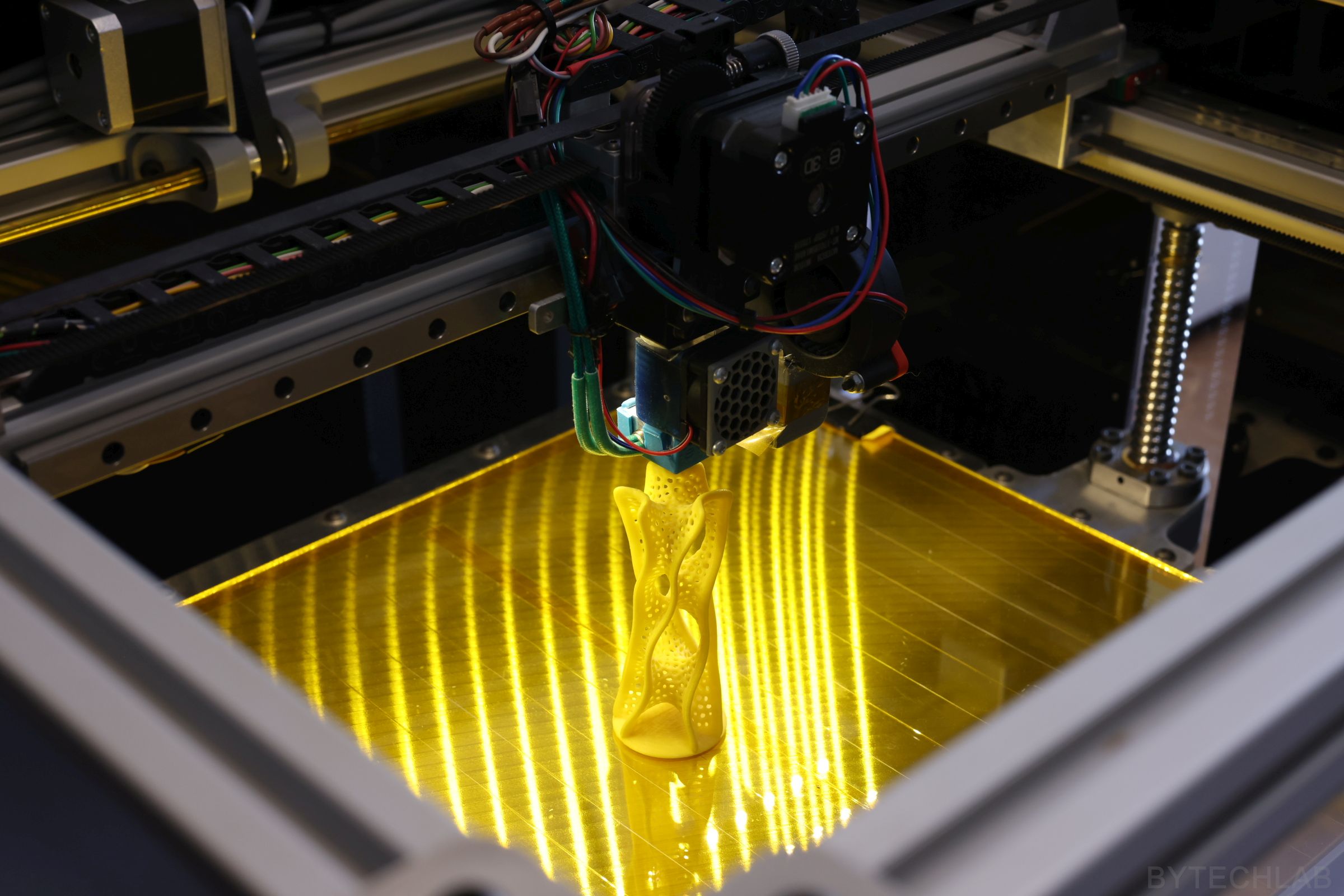
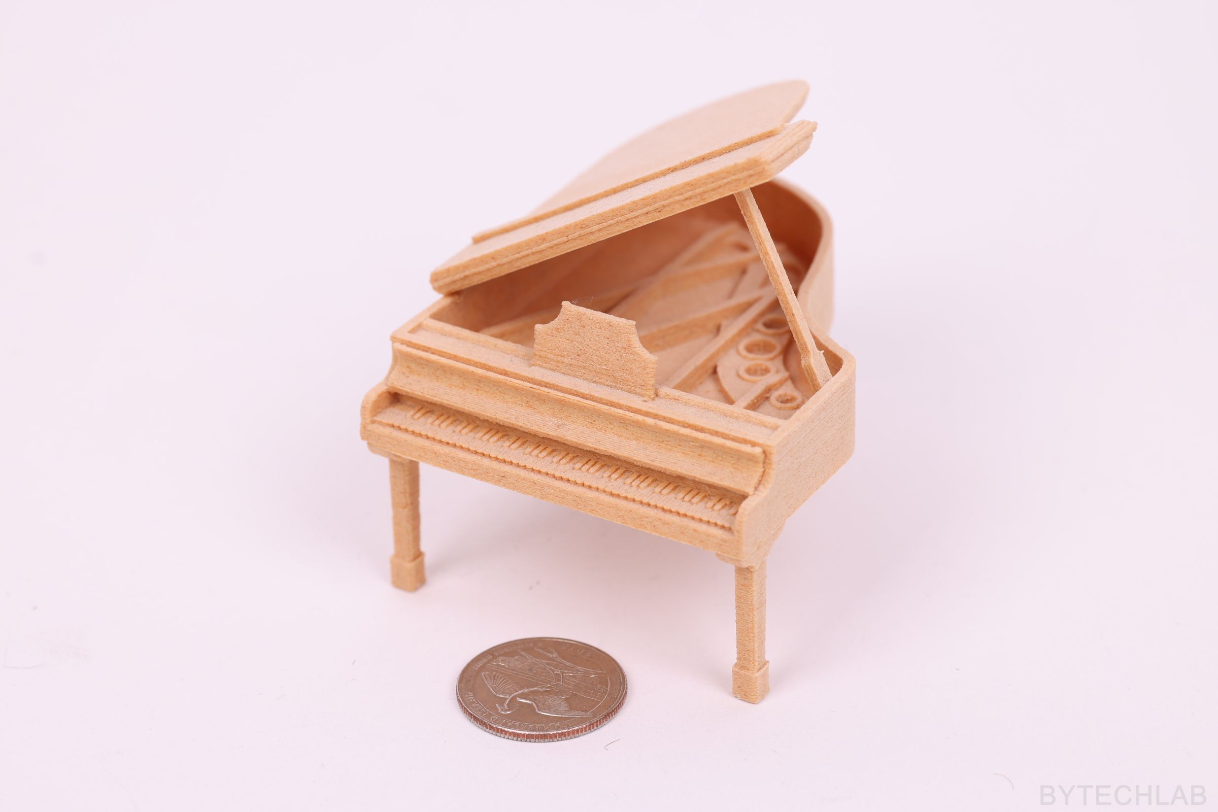
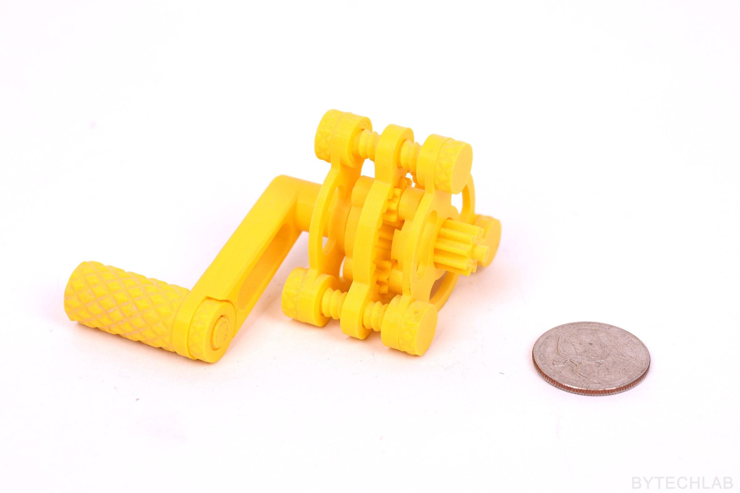
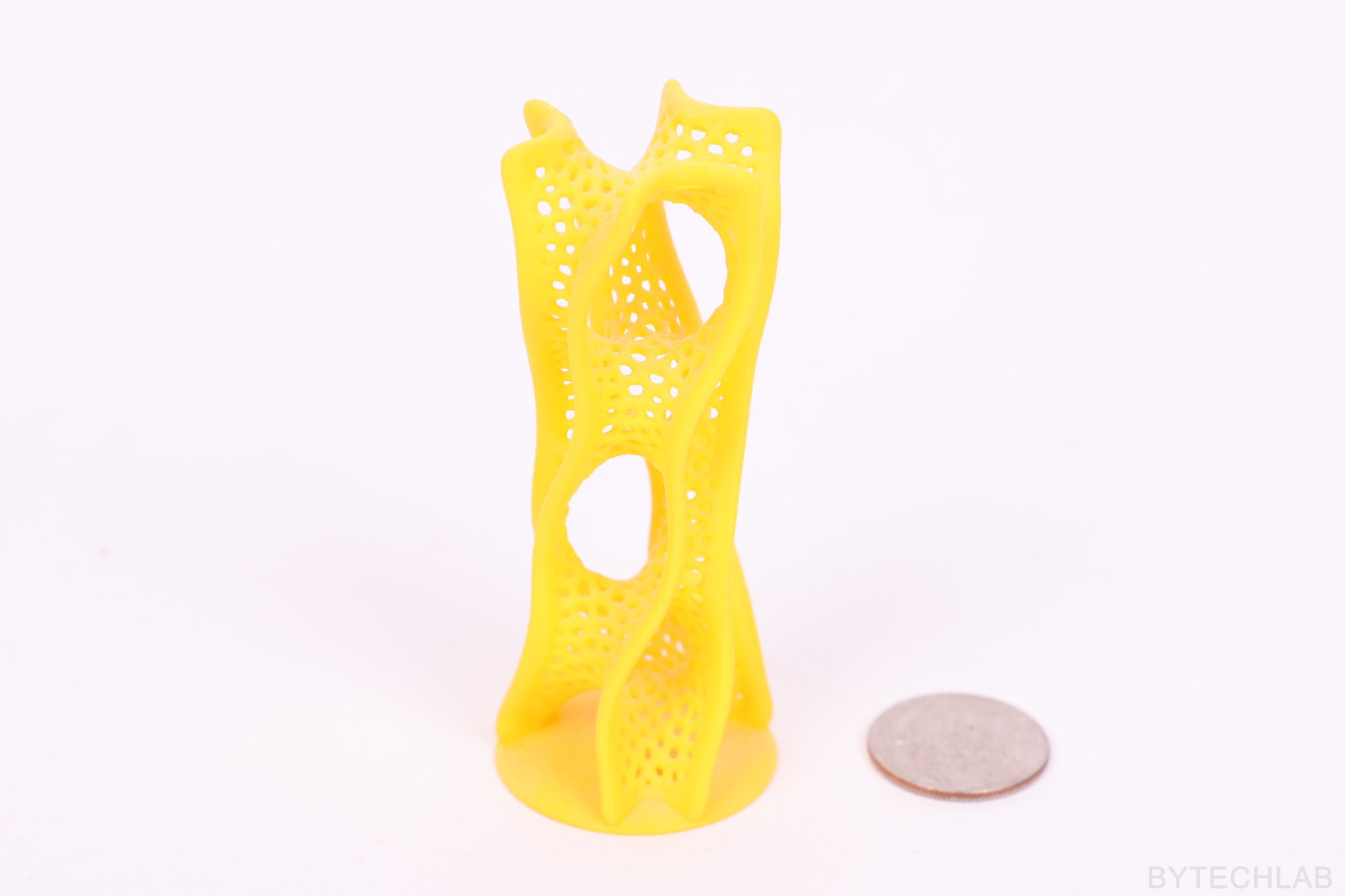
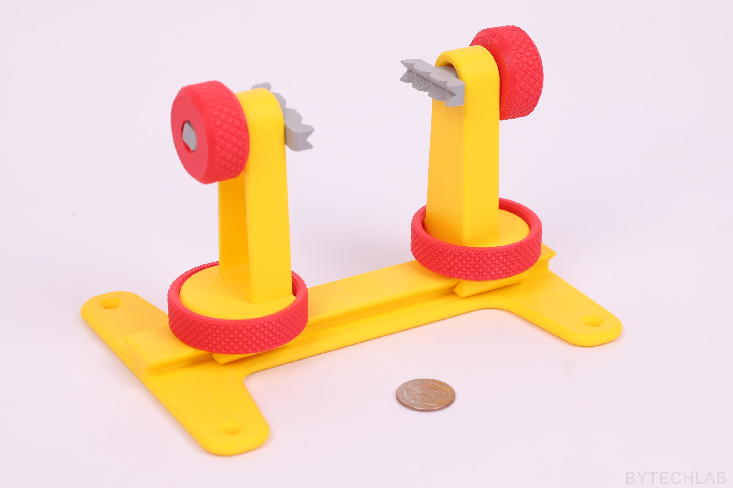
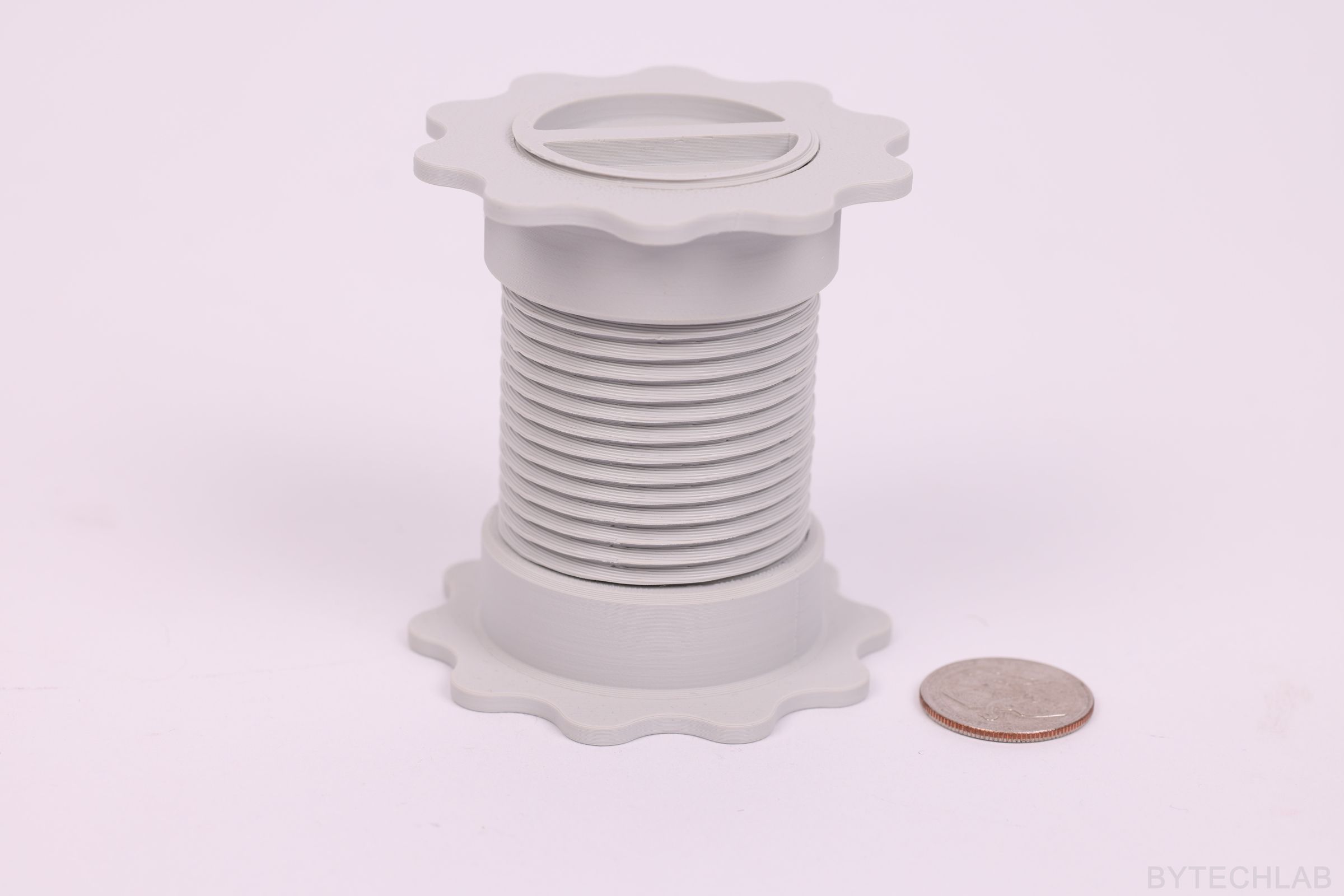
FDM 3D PRINTER (RAPTOR-360) SAMPLE PRINTS
SUMMARY
I am very happy with this printer, I did most of the things everything exactly as they should have been done. I think it’s safe to say that this is one of the largest and the most “bulletproof” 3D printers in the world. After using this printer for a year I can tell that many things could have been done better. The printer definitely is not perfect, but it’s not bad either. I think that the biggest drawback of the current design is the very heavy X-axis which is made of 20×40 aluminium extrusion. Because of the heavy X axis the printer can’t print very fast or achieve high accelerations. Despite this, the overall print quality and dimensional accuracy is great. I have lots of ideas for new upgrades and modifications that will improve this design even further.