I have designed and built this mostly 3D printed discone antenna mainly because I needed a wideband antenna for my SDR ( Software Defined Radio) to receive signals from my own RF projects (like LoRa) and to receive other signals ( Ham Radio, Airband etc.).
There are many commercially available discone antennas but usually they are quite expensive, this antenna can be built for about 100-200 USD.
This antenna was designed to work well between about 80 MHz to 1 GHz, but measurements show that it can operate at higher frequencies up to 6 GHz reasonably well.
The project includes a design of a wideband preamp together with a USBC powered bias tee to amplify the RF signal before entering long coaxial cable that is used to connect the antenna to your SDR.
The antenna was designed in the way so that it can be built easily with use of 3D printer and some other tools that you probably already have. It is much better when it comes to performance, rigidity, etc. to build the antenna from CNC milled metal parts but this is much more expensive and not everyone has a access to CNC machining shop.
Below I will describe the entire process of designing and building such an antenna so that you can make one by yourself.
1) Initial simulations – Simplified parametric model
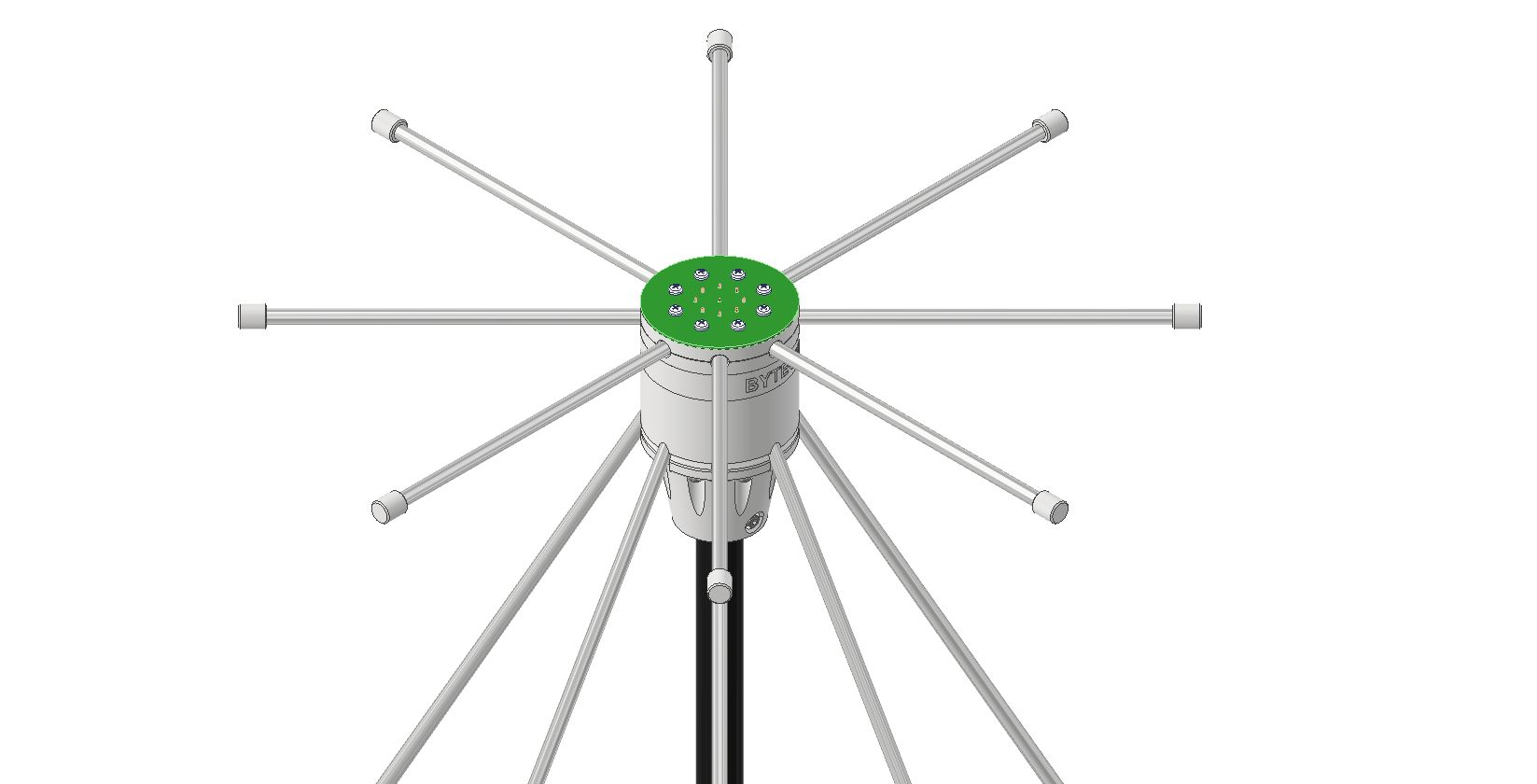
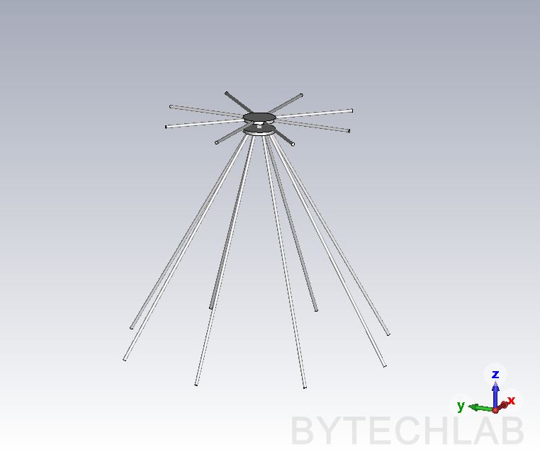
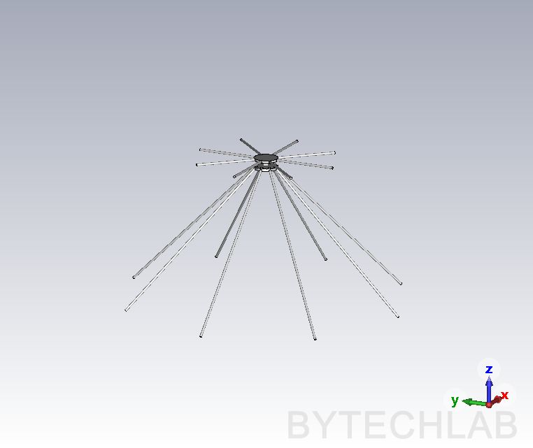
As a first step I have created a fully parametric 3D model in CST Studio. This model allows me to change every single dimension of the antenna with a single mouse click. It also allows me to do parametric sweeps to look for the dimensions that give me the best results. On the renders below you can see the angle of the cone being changed to check the effect on the antenna characteristics. Based on the parametric analysis I have chosen configuration of the dimensions that fits my needs the most (good |S11|, realized gain, beam shape, efficiency, etc.).
2) Final MCAD design based on simplified model
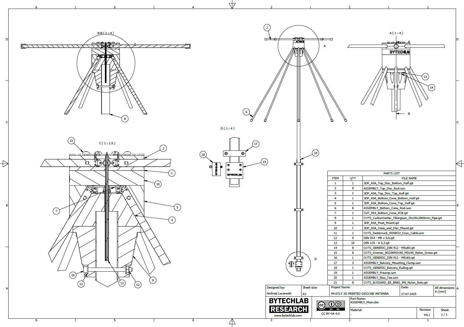
The parametric model from CST Studio is simplified and does not take the manufacturing constraints into account. That’s why I have redesigned the whole antenna in Autodesk Inventor to add important features / details (based on the simplified model). I will describe some of them below:
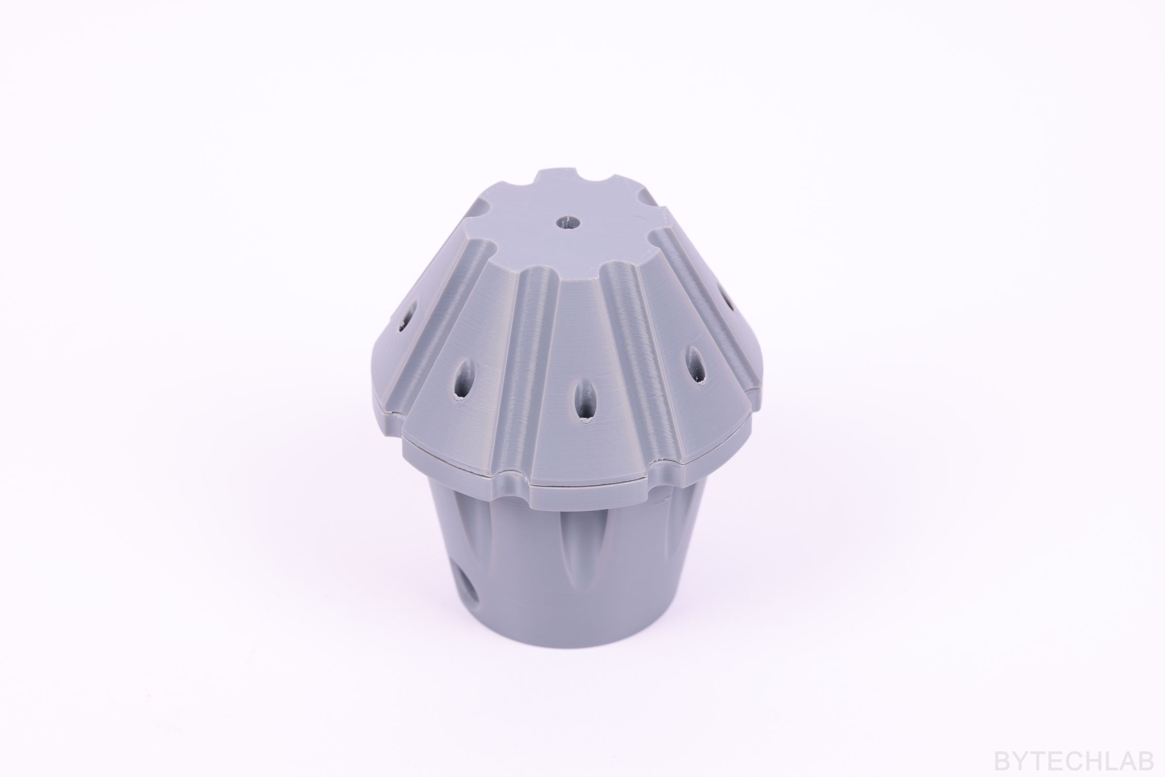
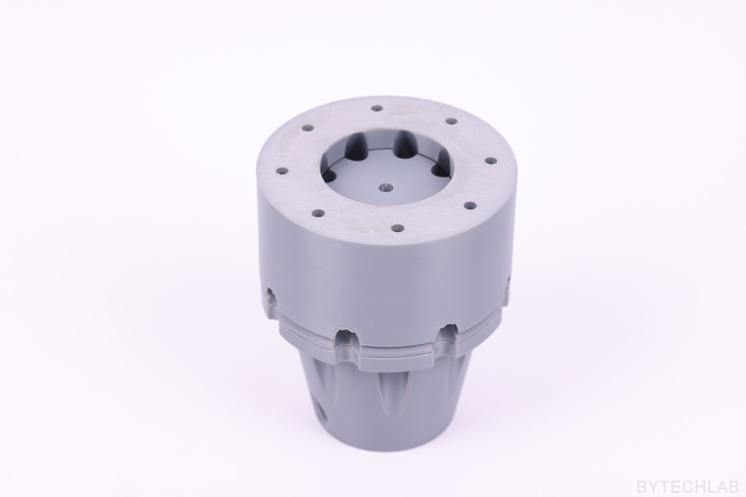
- The whole antenna body was cut into multiple parts to make the 3D printing easier (FDM),
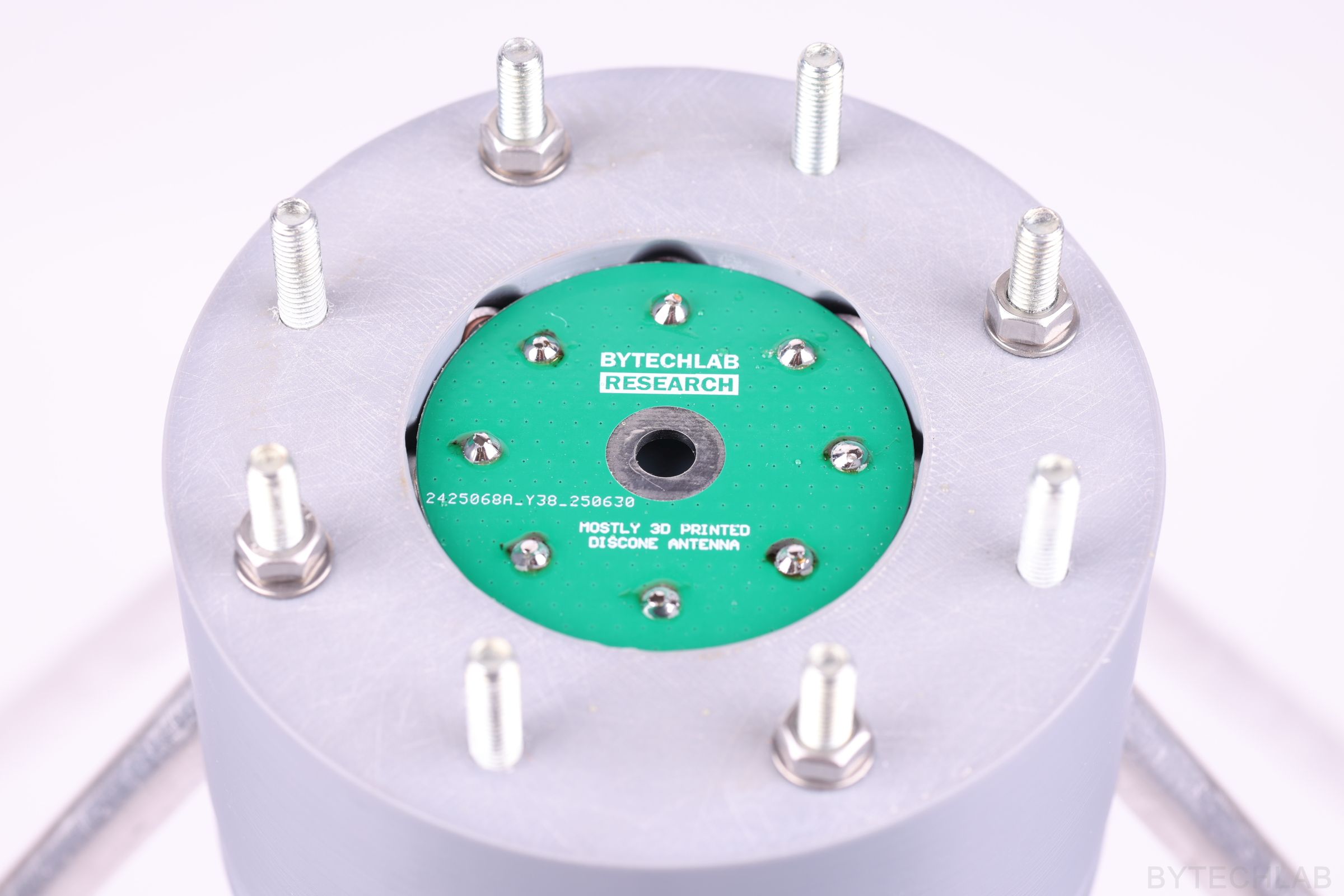
- Cone and disc PCB’s were designed in order to connect the rods together with use of copper wires and screws,
- Balcony railing mounting system was added (clamps etc.)
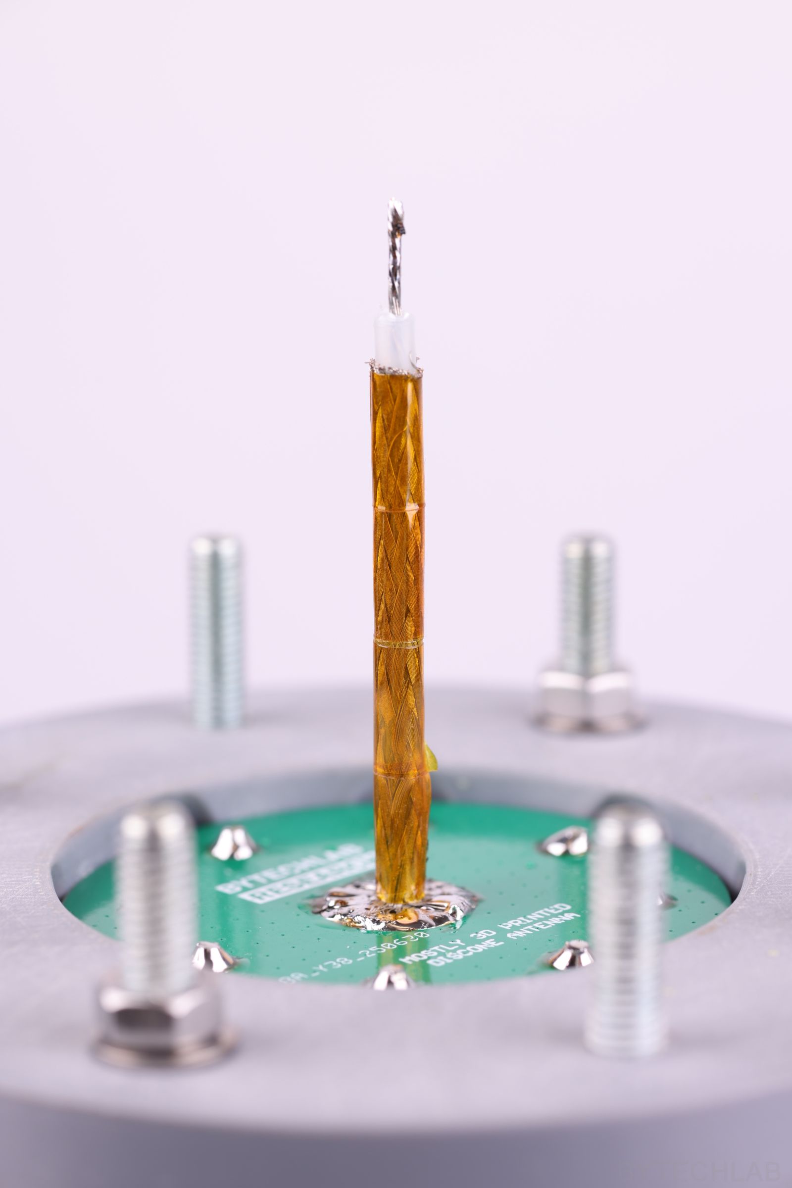
- Coaxial feed was designed and optimized to get the best performance,
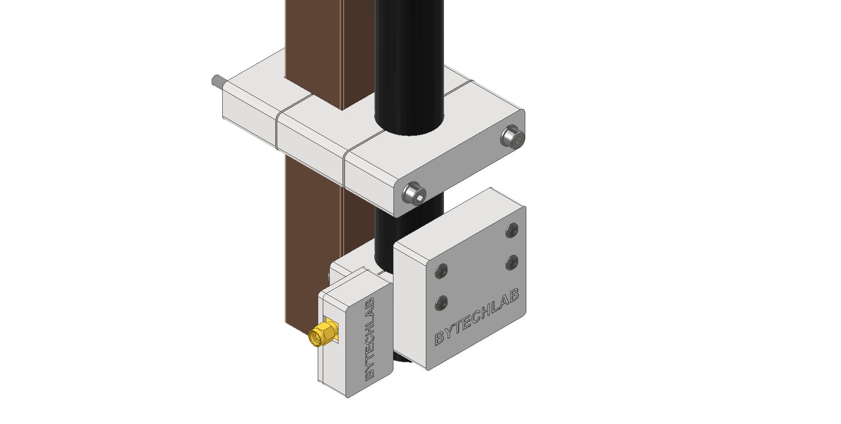
- Cases for both preamp PCB and bias tee PCB were designed,
In the GitHub repository (MCAD folder) you can find the following files:
- Autodesk Inventor project of Mostly 3D Printed Discone Antenna,
- Exported STL files for 3D printing,
- Exported STEP file of the whole assembly,
- Exported PDF file with assembly drawing, BOM and assembly instructions,
- Exported assembly renders,
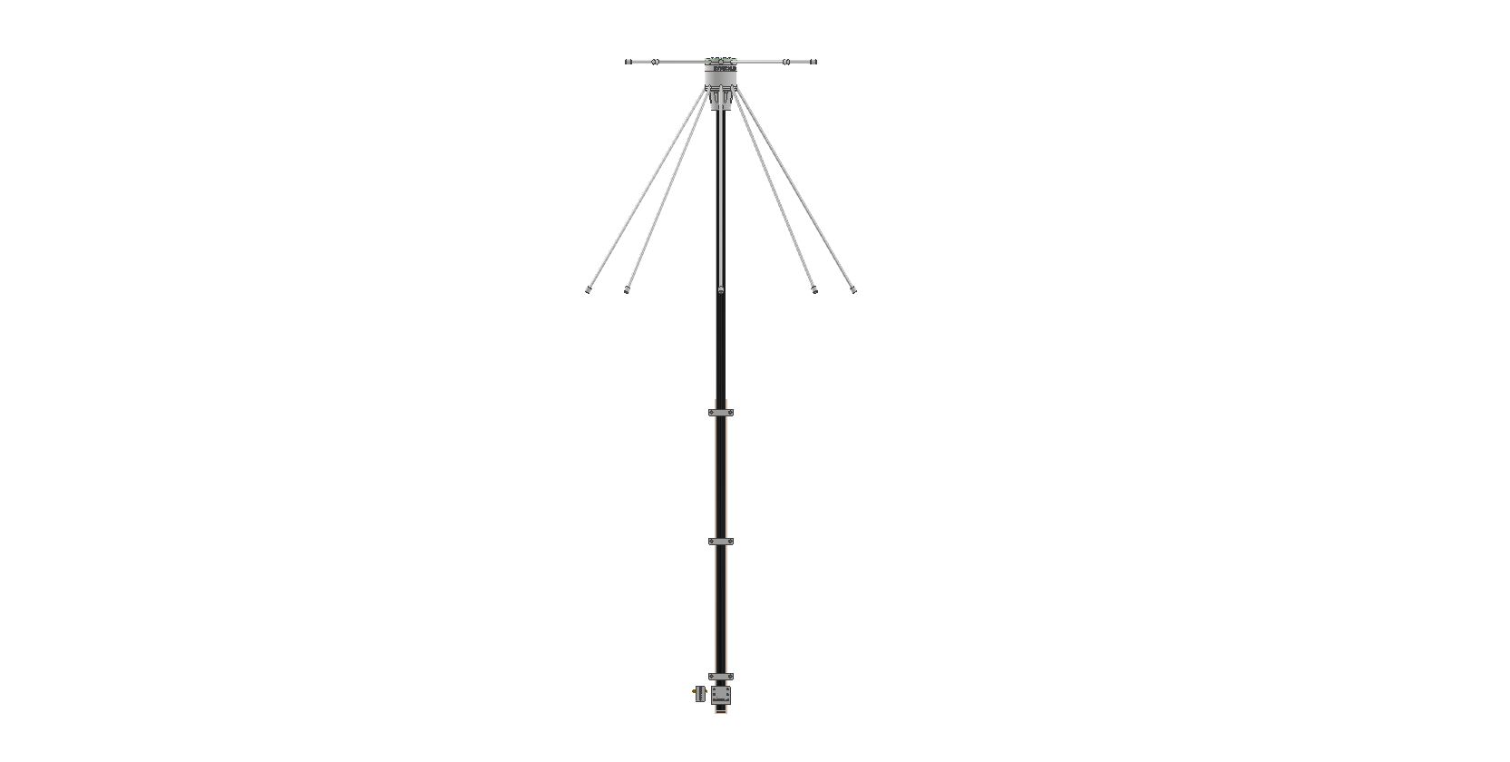
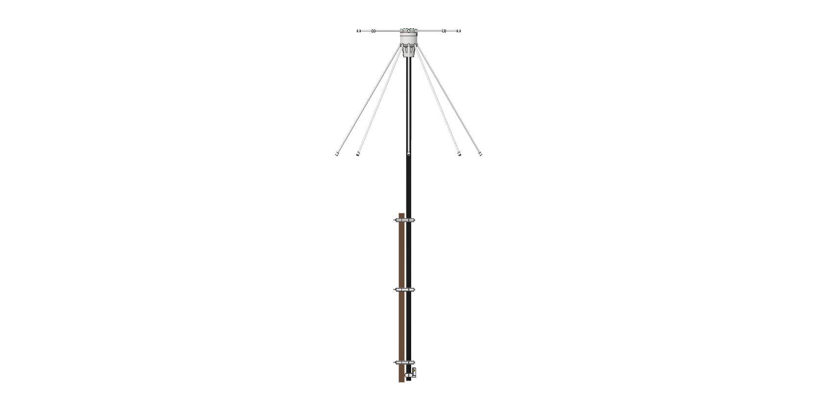
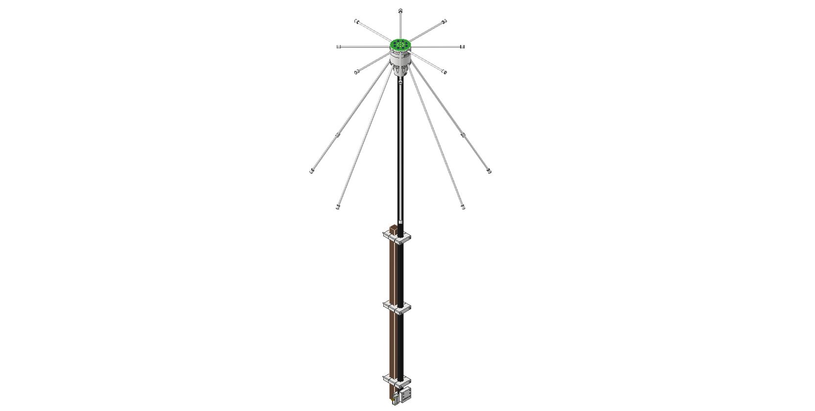
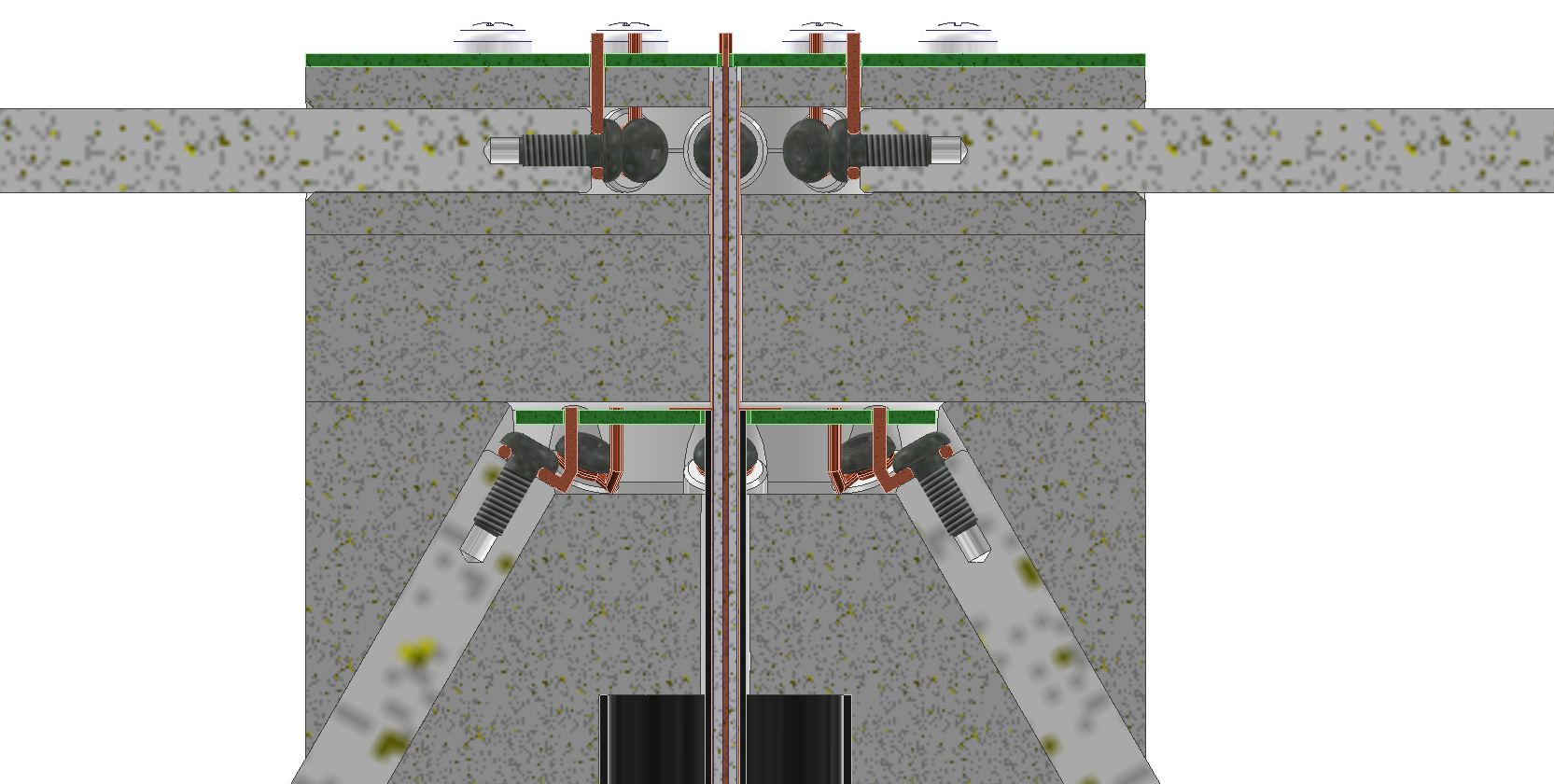
Below you can also find some renders of the final design, please take a look at the antenna cross section on render “MCAD – Render – 4” which shows how the whole thing is built inside.
3) ECAD design (preamp & bias tee)
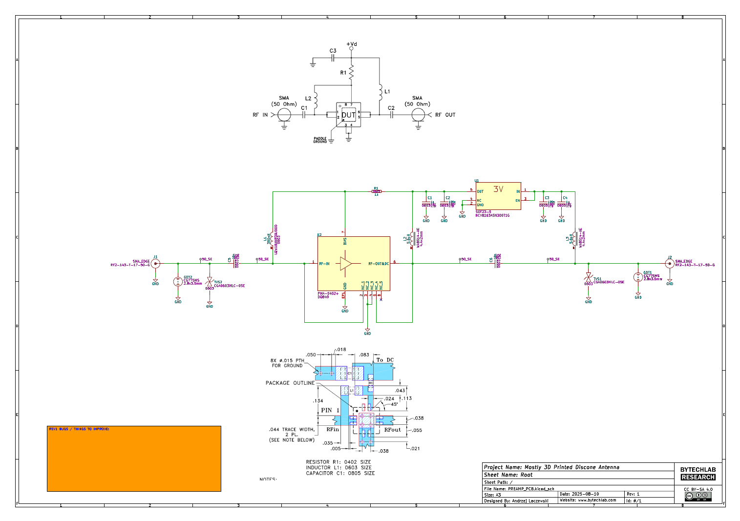
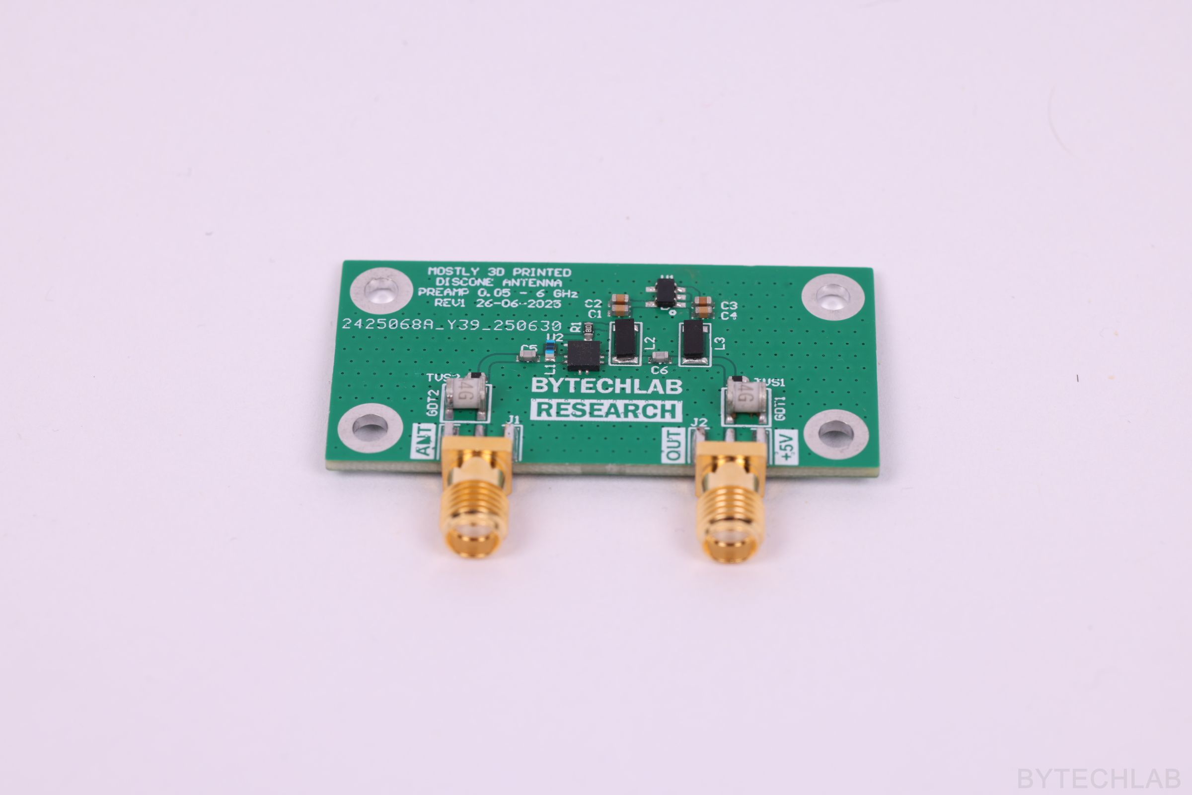
To amplify weak signals from the antenna I have designed a simple preamp PCB which includes:
- Mini Circuits PMA-5452+ -> LNA,
- Onsemi NCV8163ASN300T1G -> 3V low noise / high PSRR LDO,
- And some ESD & “lightning” protection (TVS + GDT),
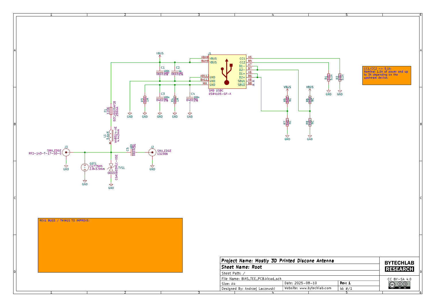
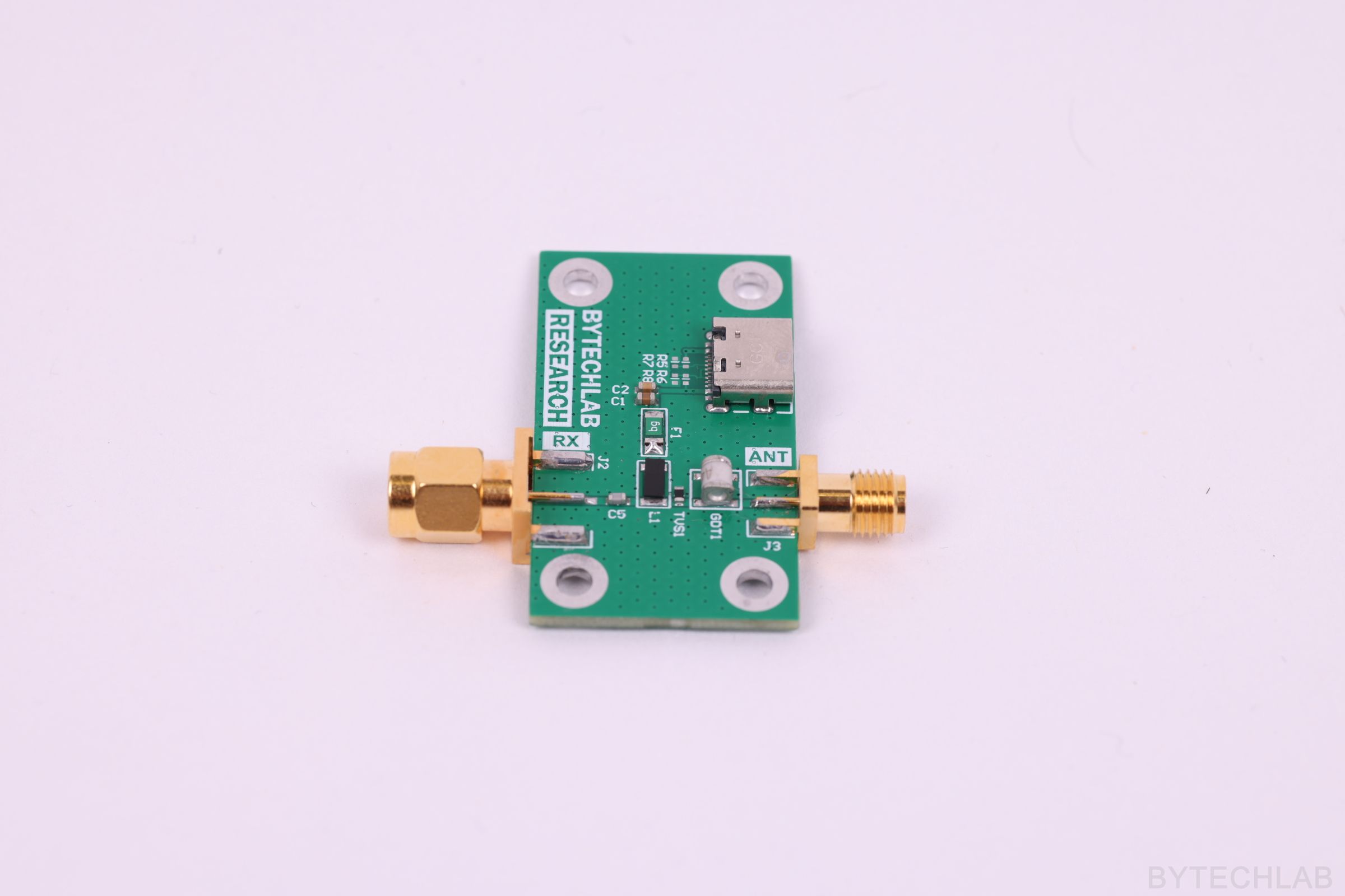
Preamp PCB is supplied via coax cable by the bias tee PCB ( the most convenient way to power the preamp in my opinion). The bias tee PCB is intended to be connected directly to your SDR SMA connector. 5V voltage is being injected to the coax cable from the USBC connector. The bias tee PCB also has a 250mA PTC fuse built in to add some protection against short circuits. Additionally as a next level of protection I have also added a GDT and TVS to hopefully protect the SDR input from overvoltage events.
I have used a standard 1.6mm 2 layer FR4 JLCPCB stackup to make the PCB’s as cheap as possible.
In the GitHub repository (ECAD folder) you can find the following files:
- KiCAD projects of the PCB’s,
- Exported GERBER files for manufacturing,
- Exported STEP file of the PCB’s,
- Exported PDF file with schematics and layout,
- Exported BOM and P&P files,
4) Final MCAD design simulation
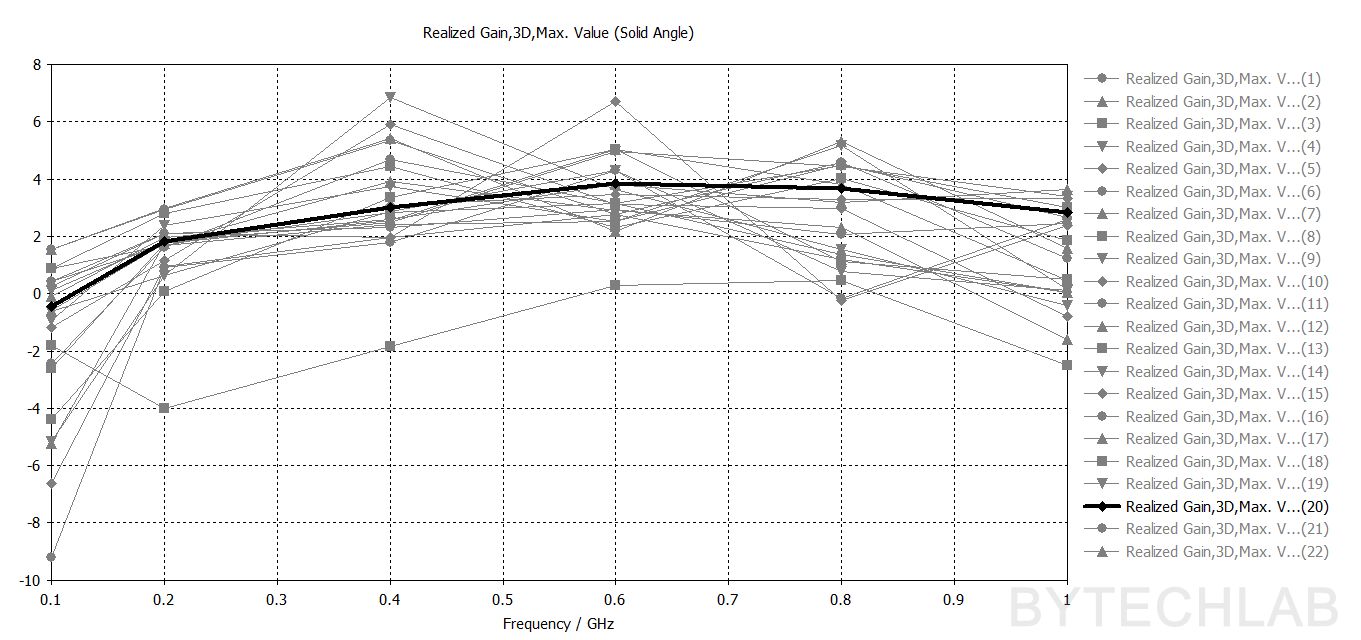
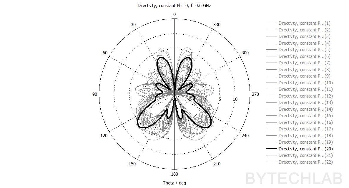
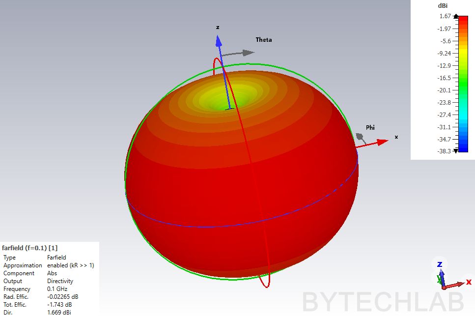
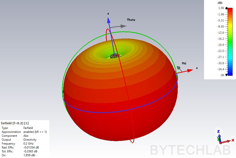
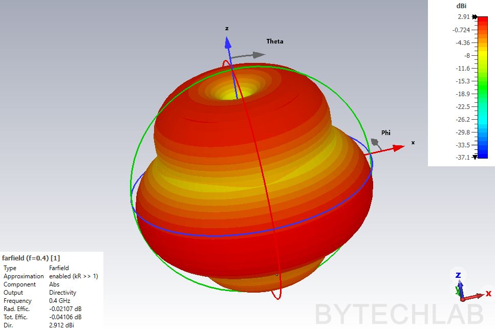
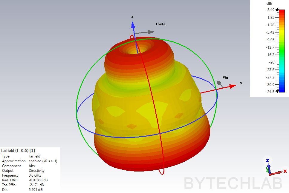
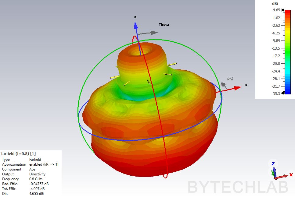
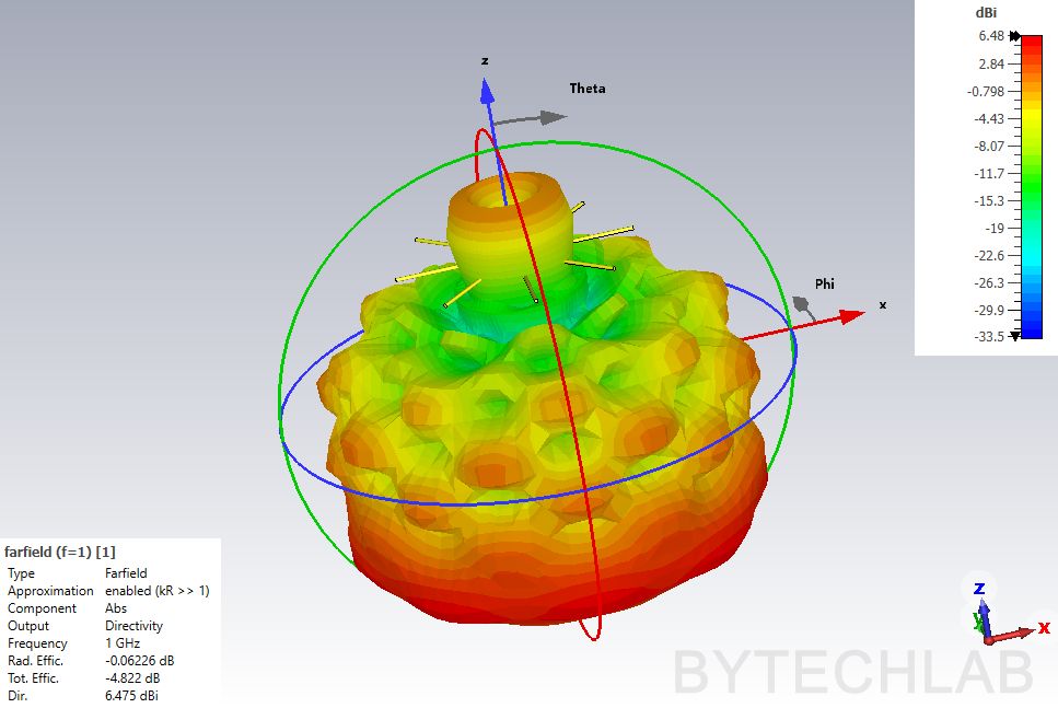
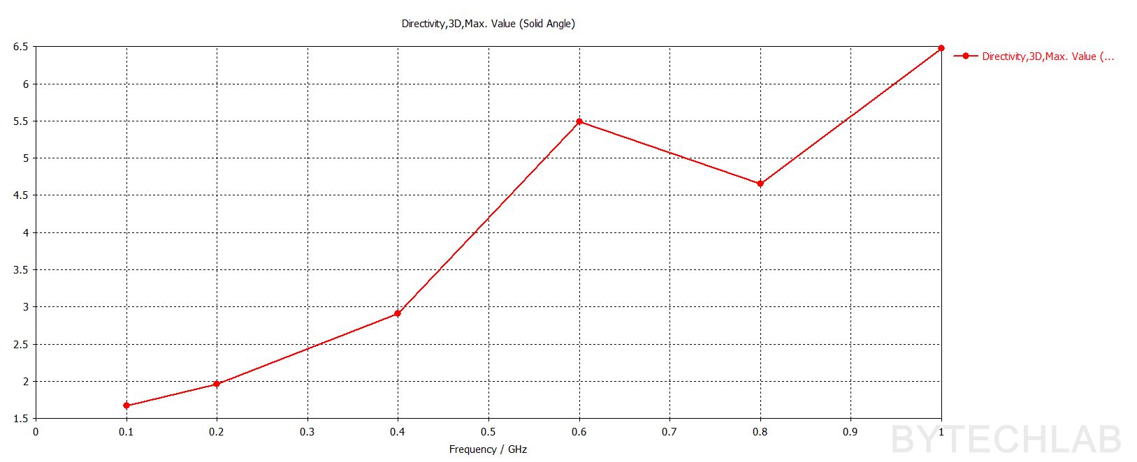
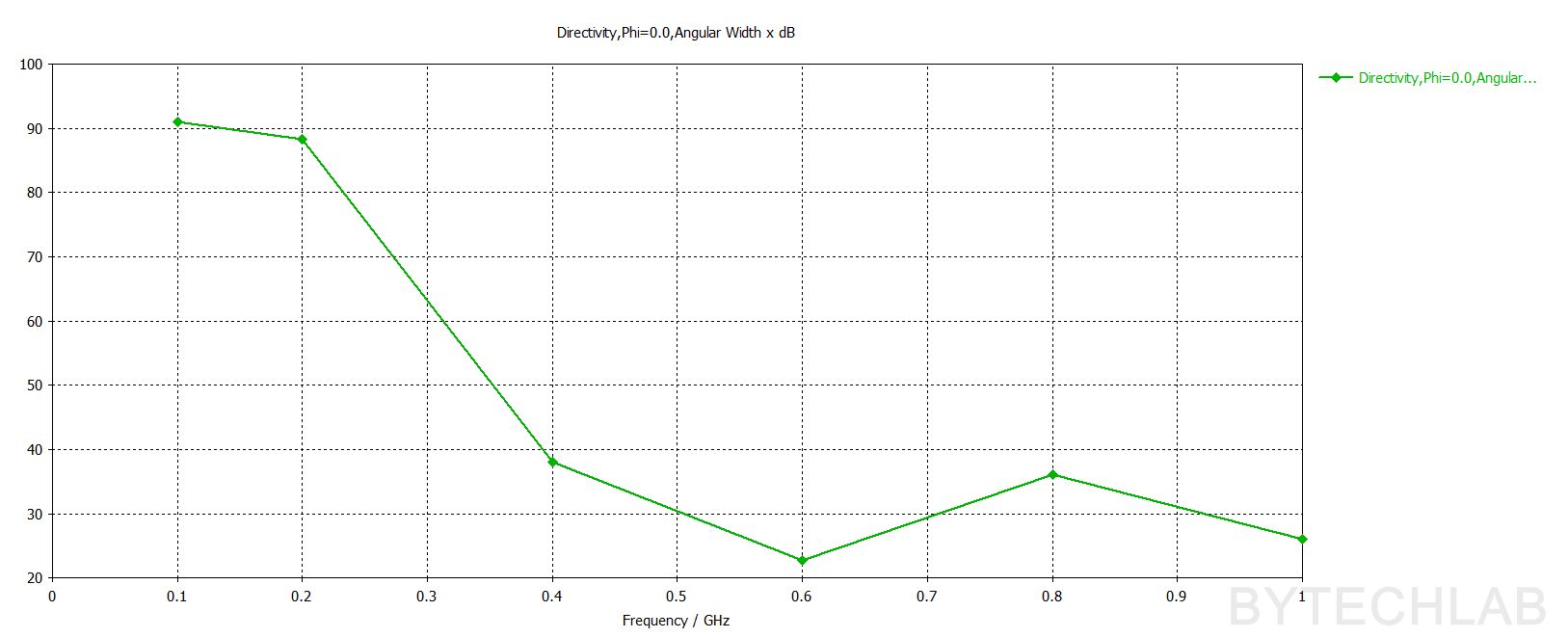
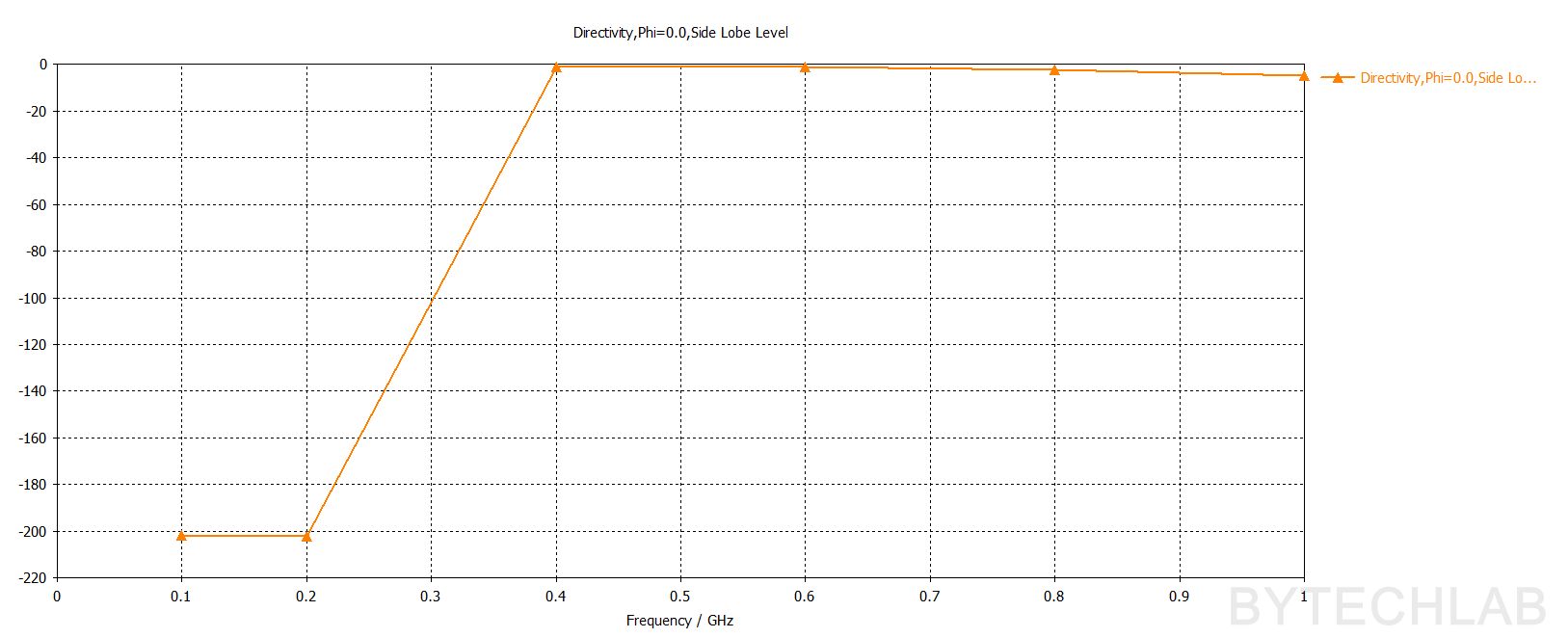
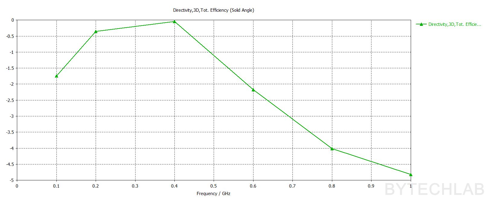
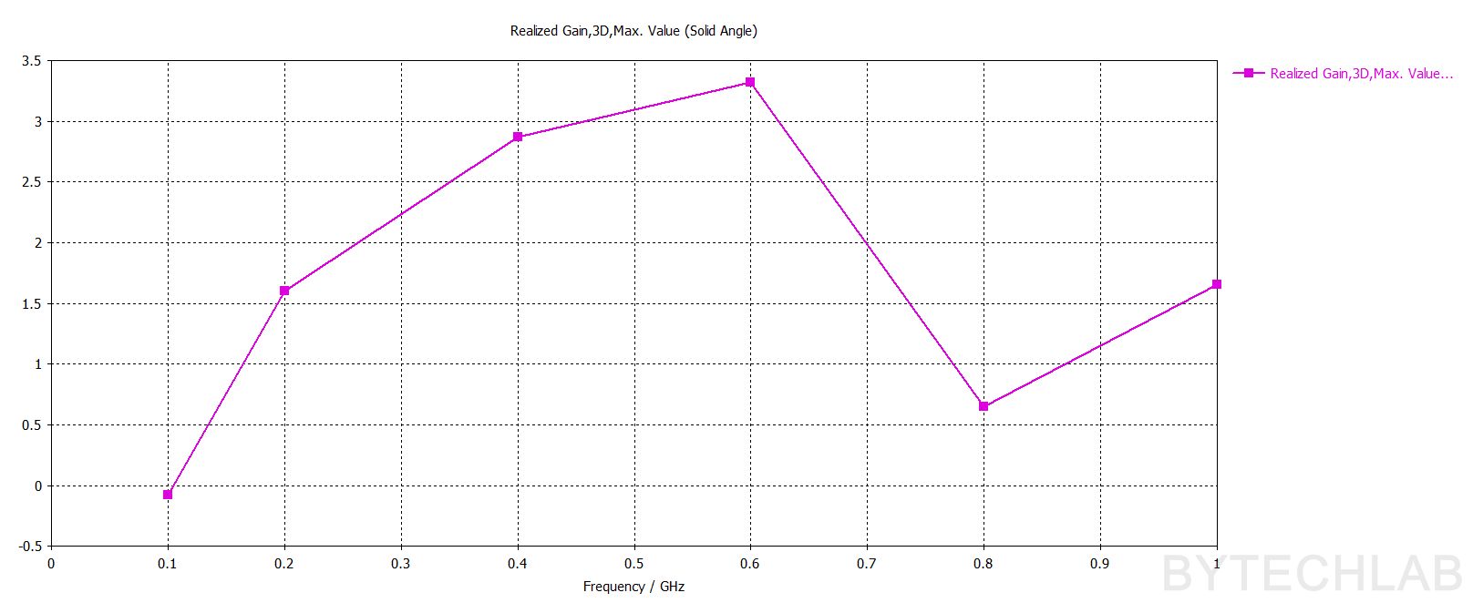
To verify the final MCAD design I have exported it from Autodesk Inventor and imported it back to to the CST Studio. To be 100% sure that this design will work well I have ran full set of simulations. On the above animation you can see the E filed propagating through the antenna at 0.5 GHz. Below you can see the 3D Farfield renders of the antenna (Directivity). As the frequency is rising the beam shape is changing from a donut shape to a more complex shape with a “sidelobes” which shouldn’t be a big problem.
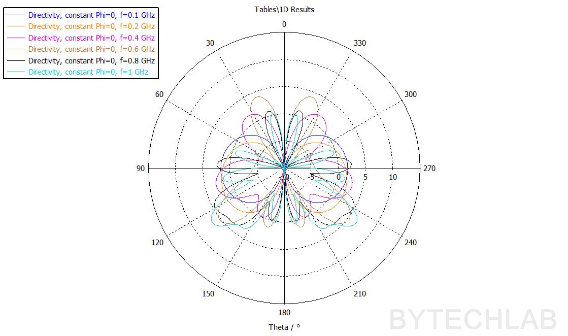
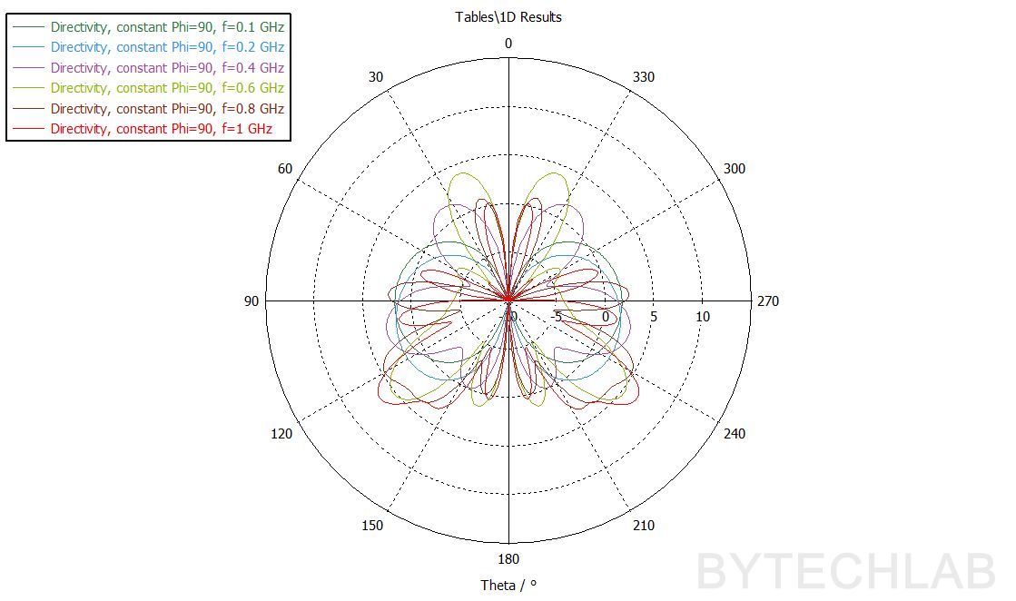
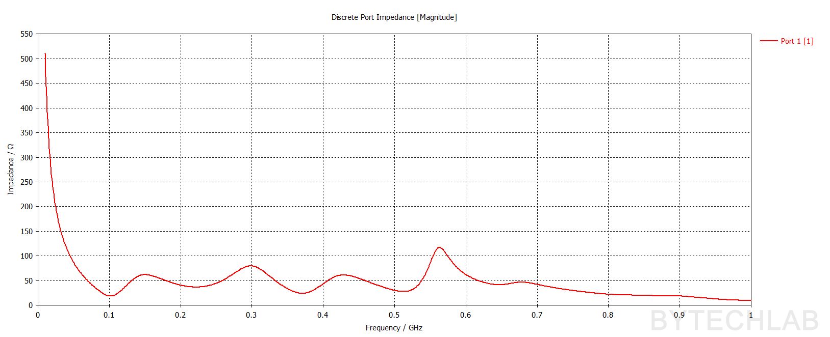
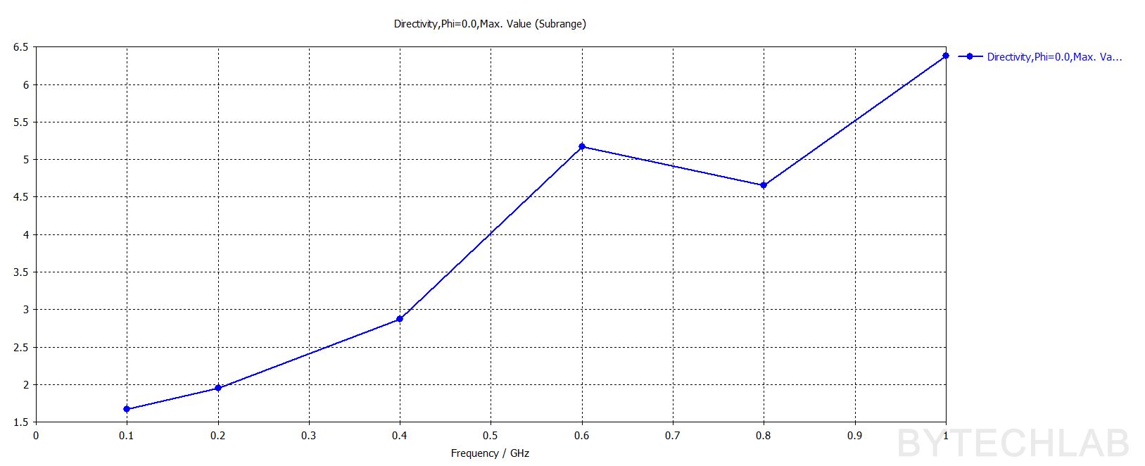
Below you can see also other antenna characteristics such as: Directivity -2D farfield cuts (phi=0,phi=90), |S11|, Port impedance, Directivity Max., Angular width (phi=0), Side lobe level (Phi =0), Total Efficiency, Realized Gain Max.
5) Manufacturing – 3D printing
Parts for the mostly 3D printed discone antenna were printed on BambuLab X1C with ASA filament. ASA filament is an excellent choice for 3D printing parts that are intended for outdoor applications due to its superior weather and UV resistance compared to materials like ABS and PETG. It is designed to withstand prolonged exposure to the elements, including sunlight, rain, and temperature fluctuations, without significant degradation. On the video above you can see the printing process of one of the antenna parts.
Recommended printing settings:
- 0.2 mm layer height,
- ASA filament,
- 75 % rectilinear infill,
6) Assembly
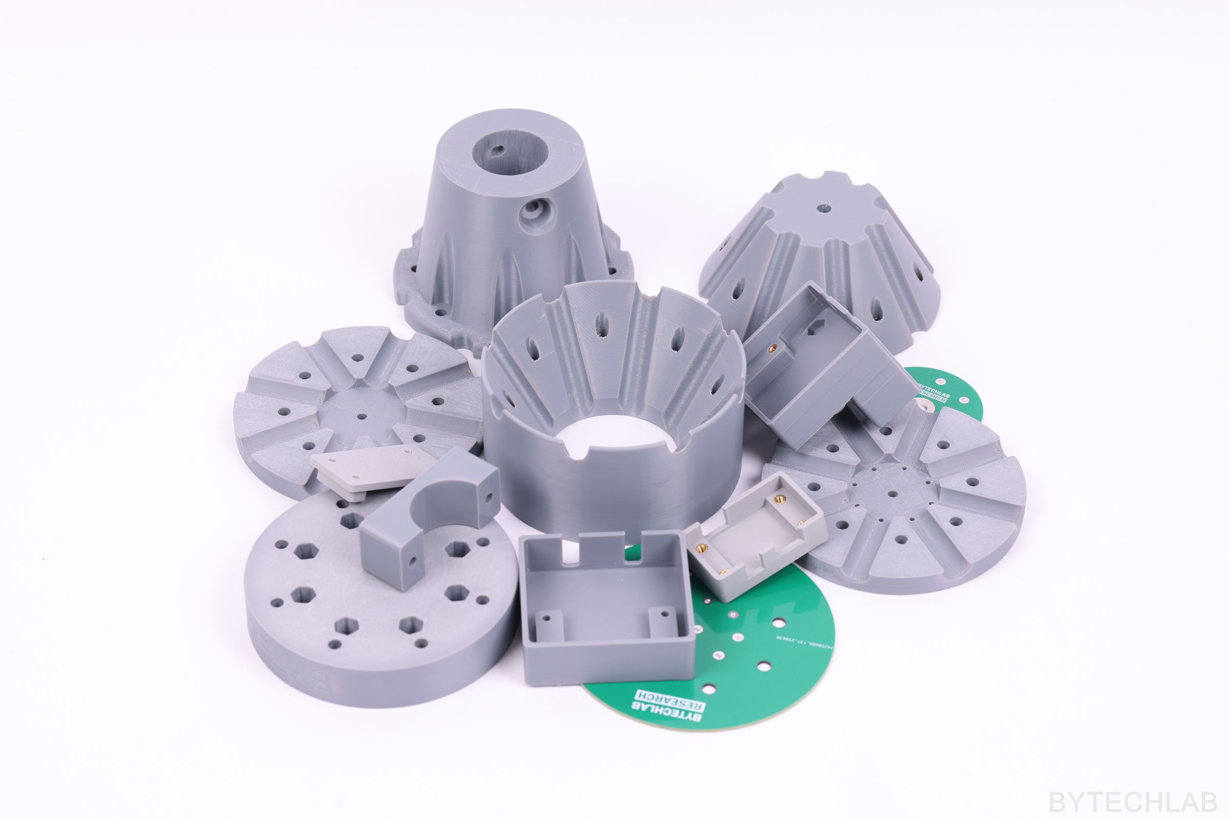
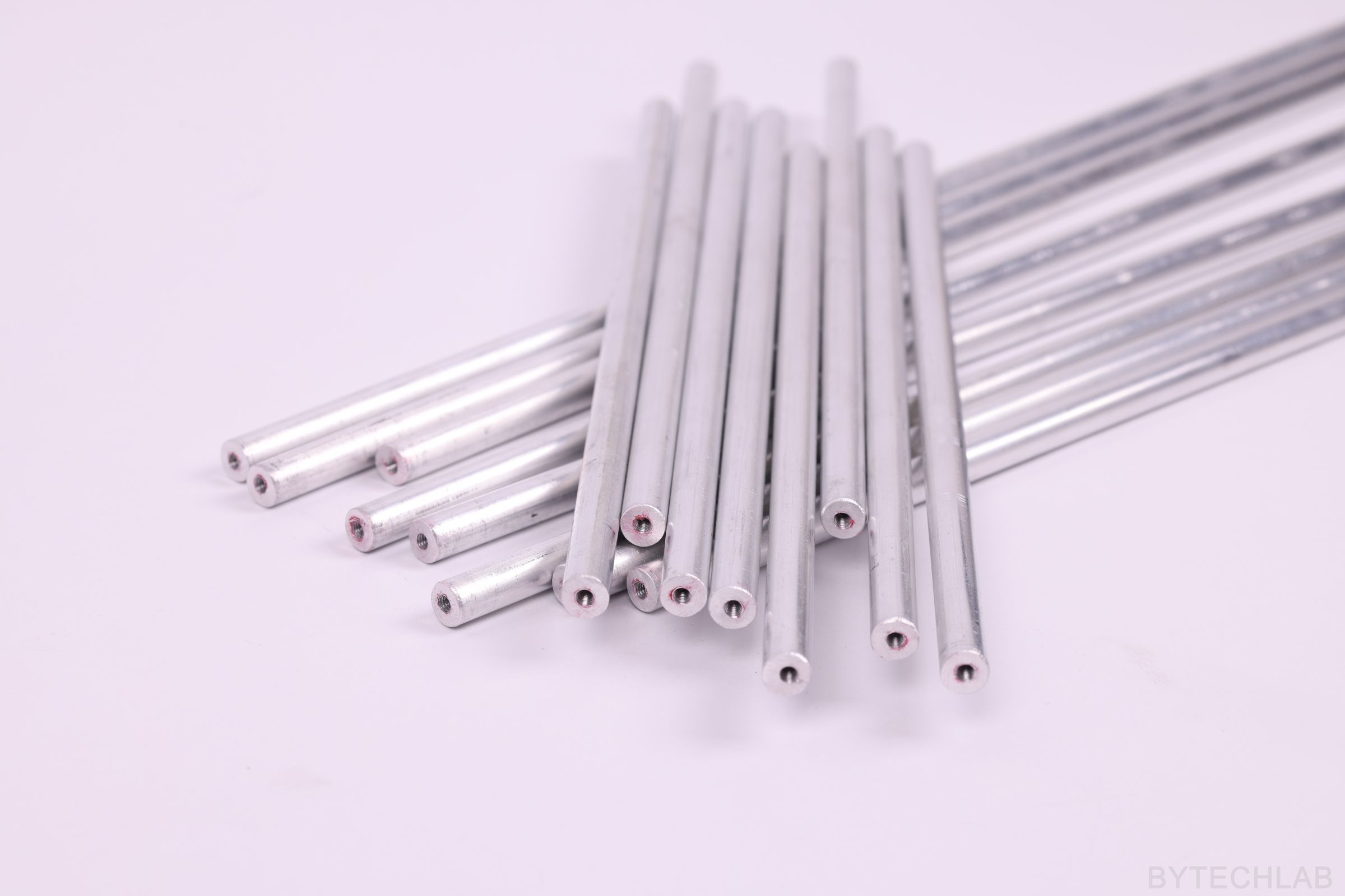
After purchasing and manufacturing all of the needed parts the whole thing needs to be assembled of course. The most time consuming step was to cut the 10mm aluminium rods to proper length and drill the holes and and tap the M4 threads. The rest of the assembly process is very easy and quick ( like a LEGO bricks ). Below you can see how the whole thing is assembled together step by step ( without the screws nuts and washers ).
To finalize the assembly process the copper wires were attached to the cone rods with use of M4 screws and later they were soldered to the cone PCB. After that RG58 coaxial cable was prepared according to the MCAD design and then the shield was soldered to the cone PCB.
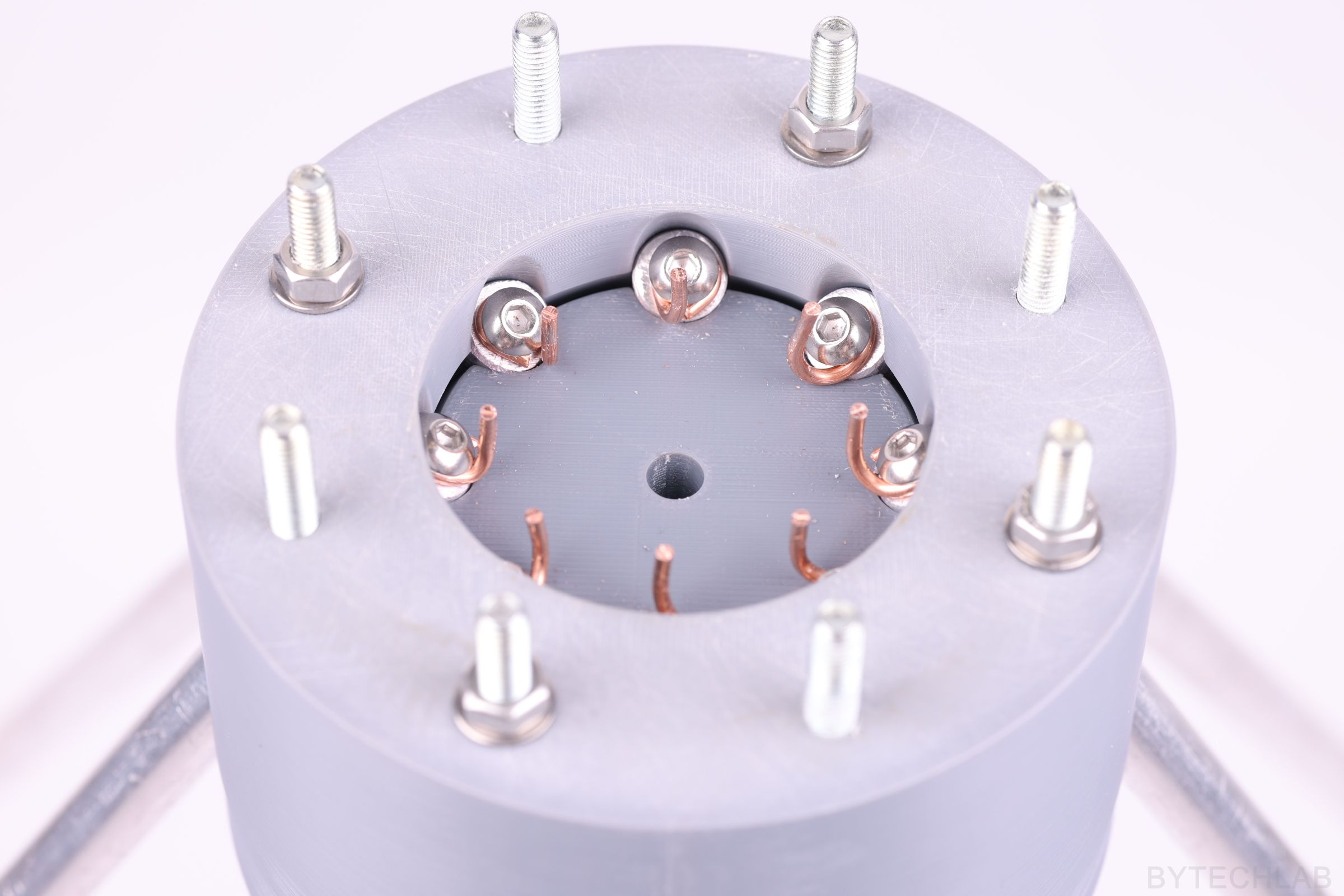

The copper wires also need to be attached to the top disc aluminum rods with the same method.
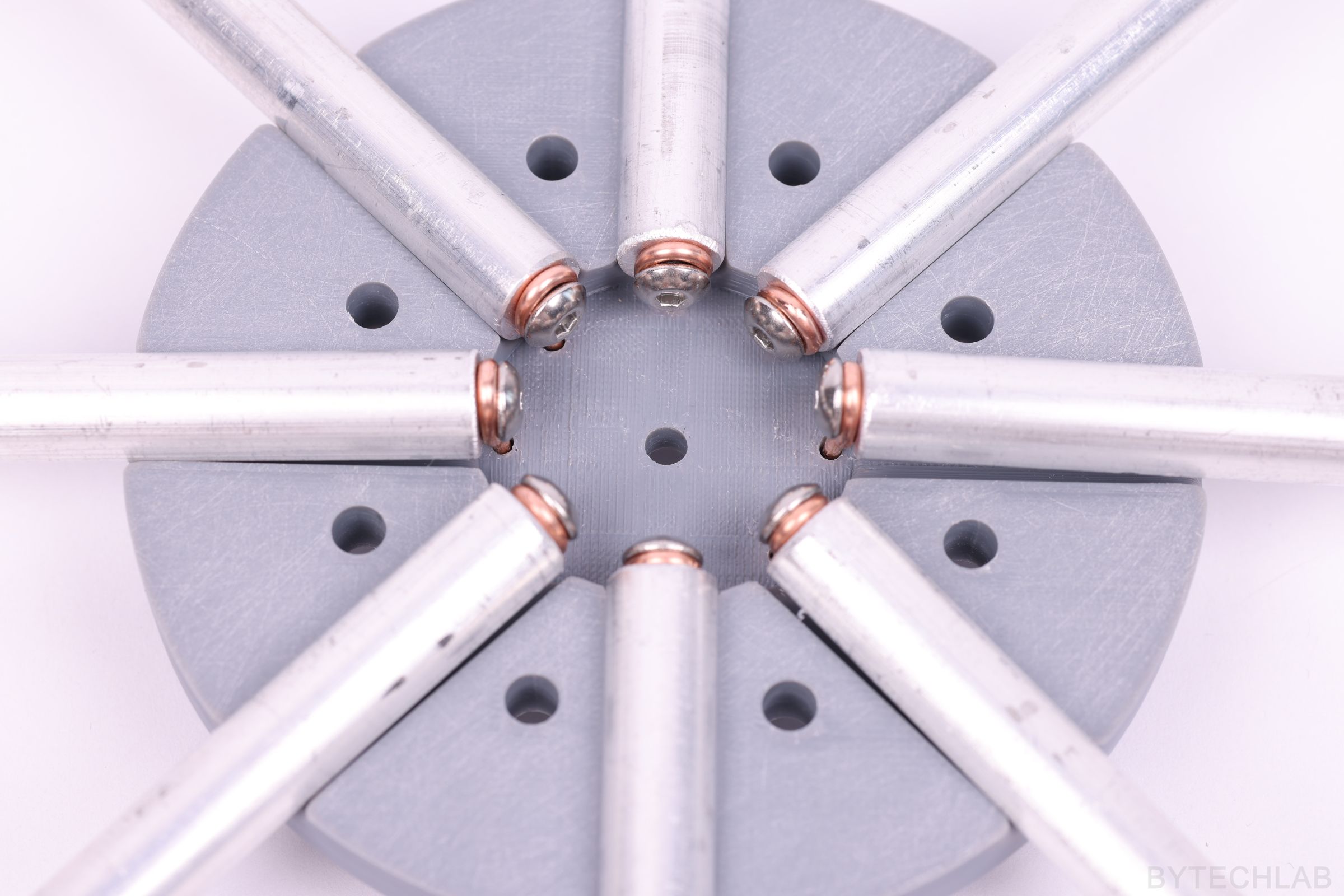
Also these copper wires are soldered to the disc PCB the same way as the cone copper wires are soldered to the cone PCB.
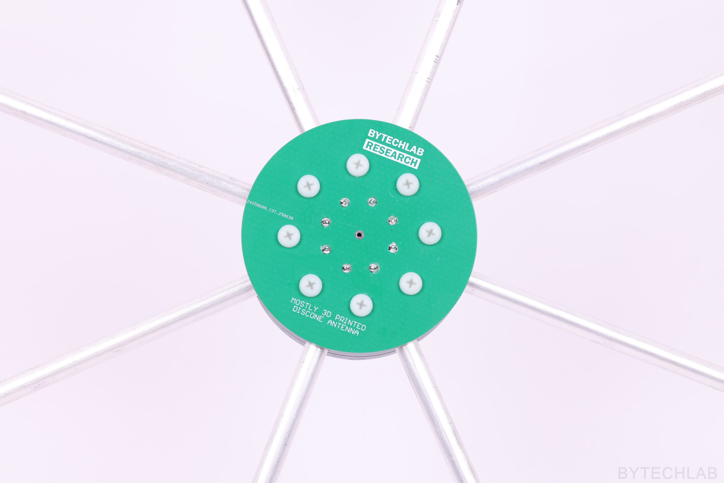
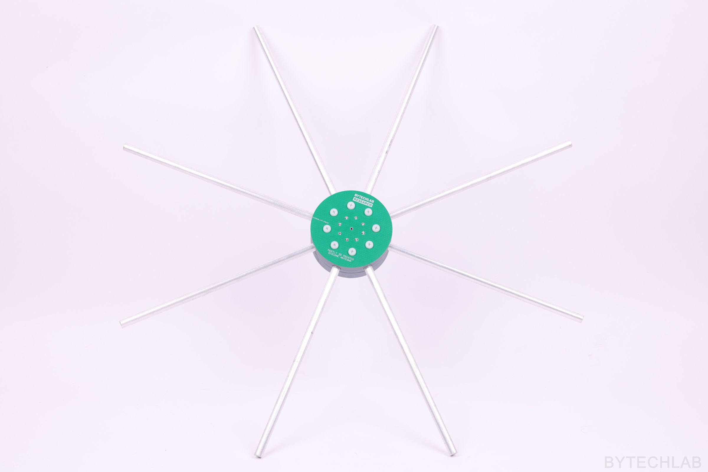
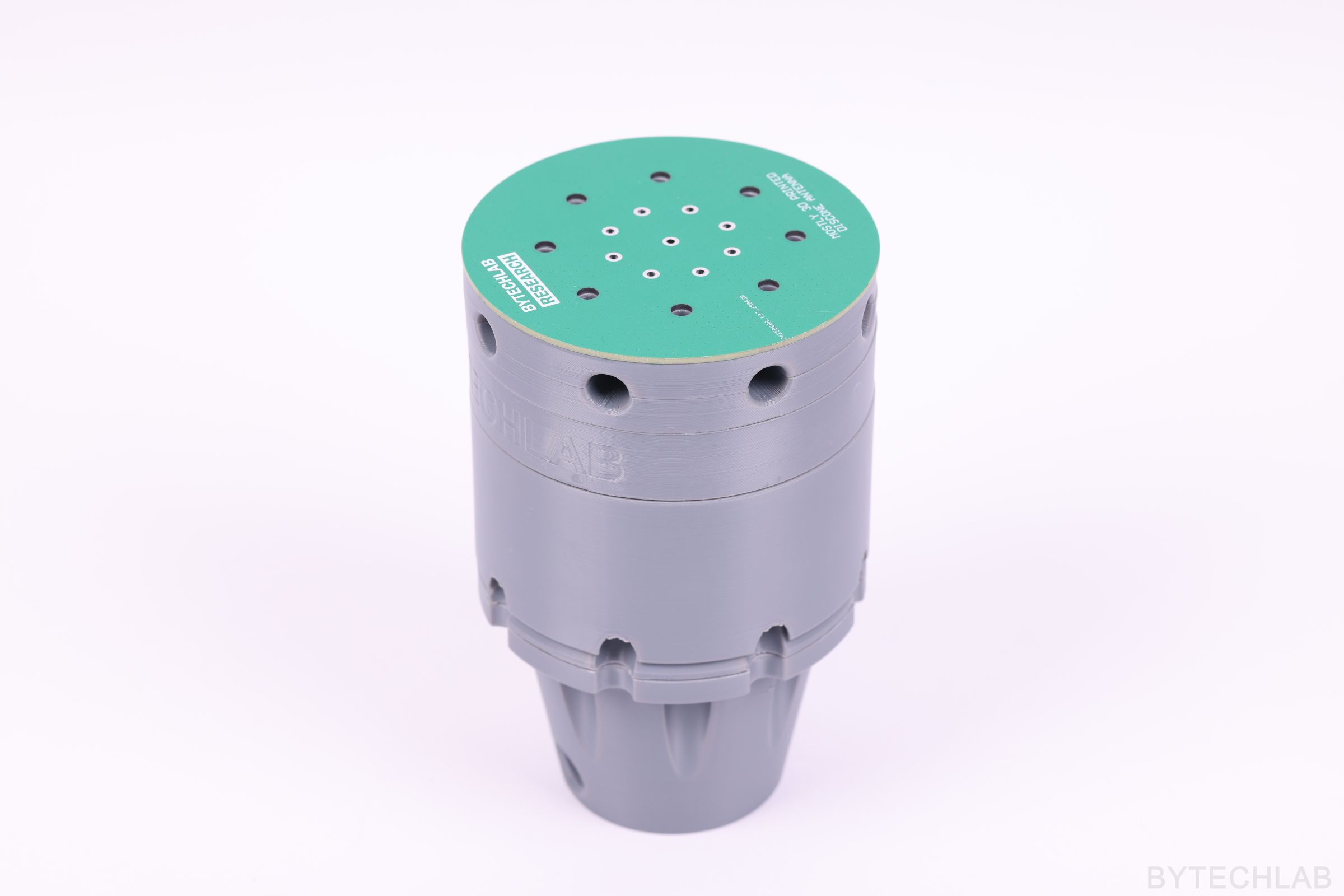
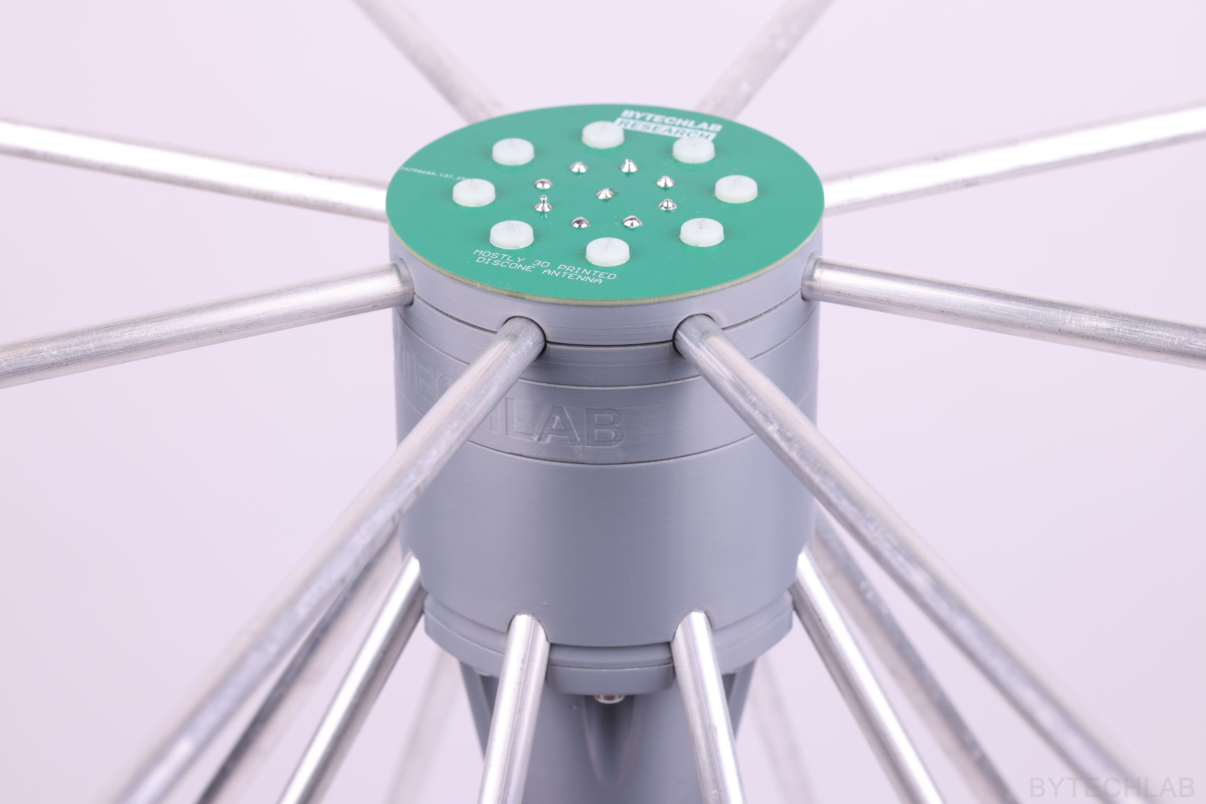
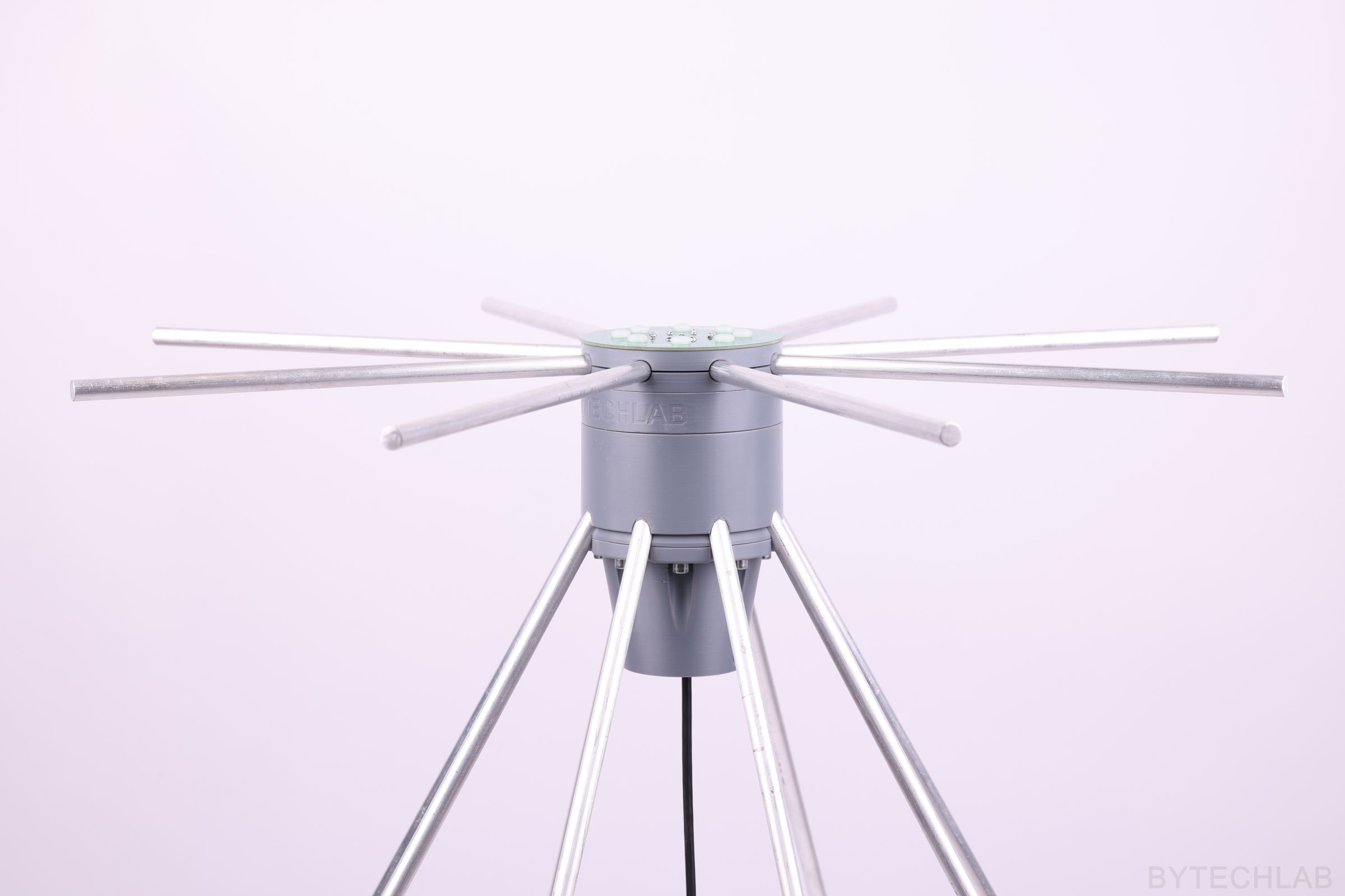
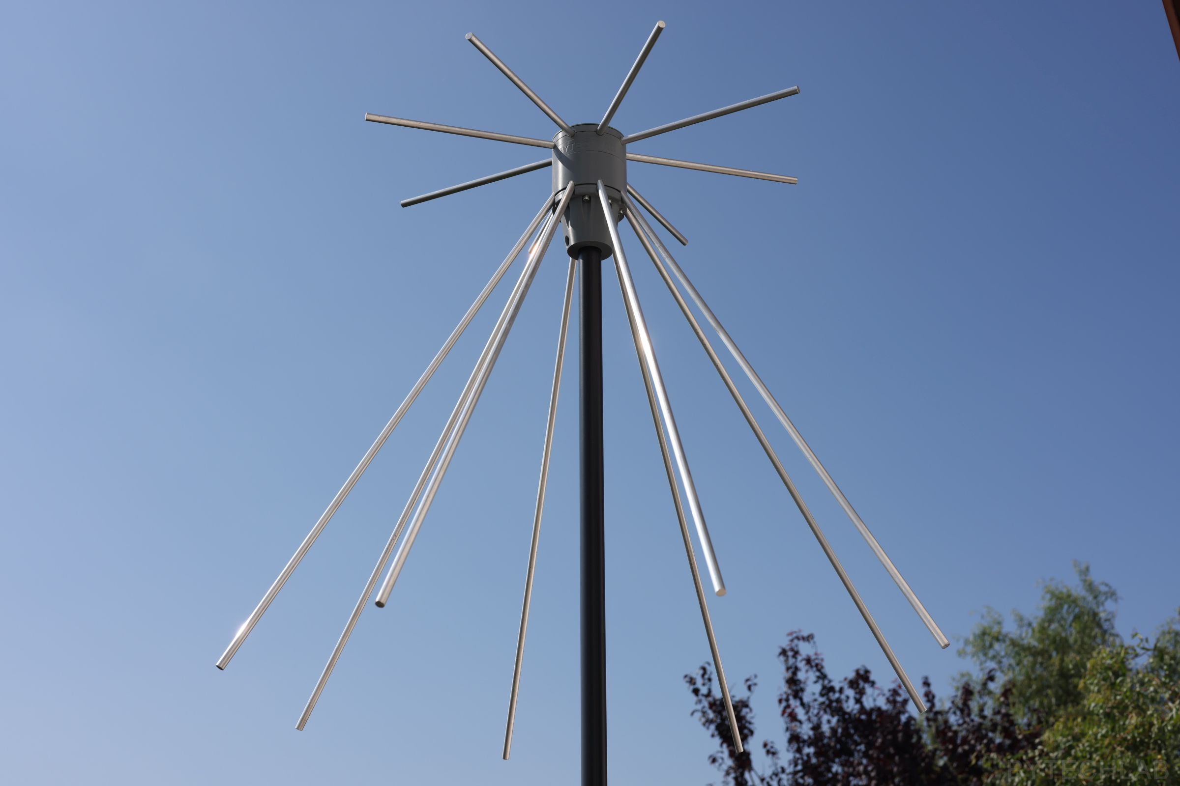
On the photos below you can see fully assembled antenna before it was mounted on the balcony railing.
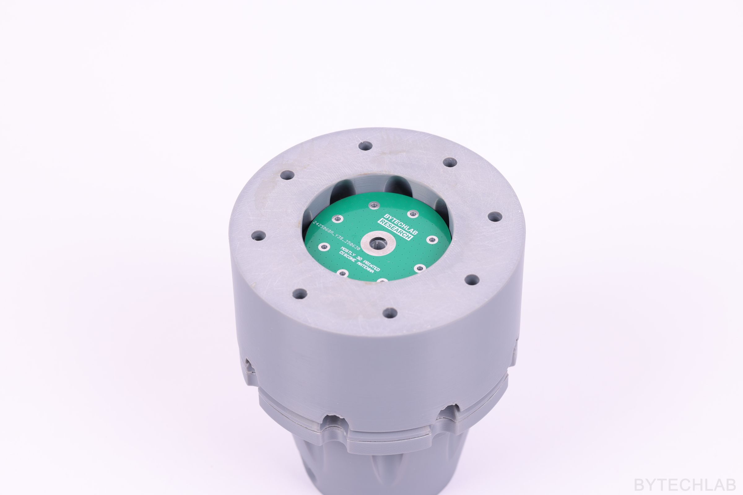
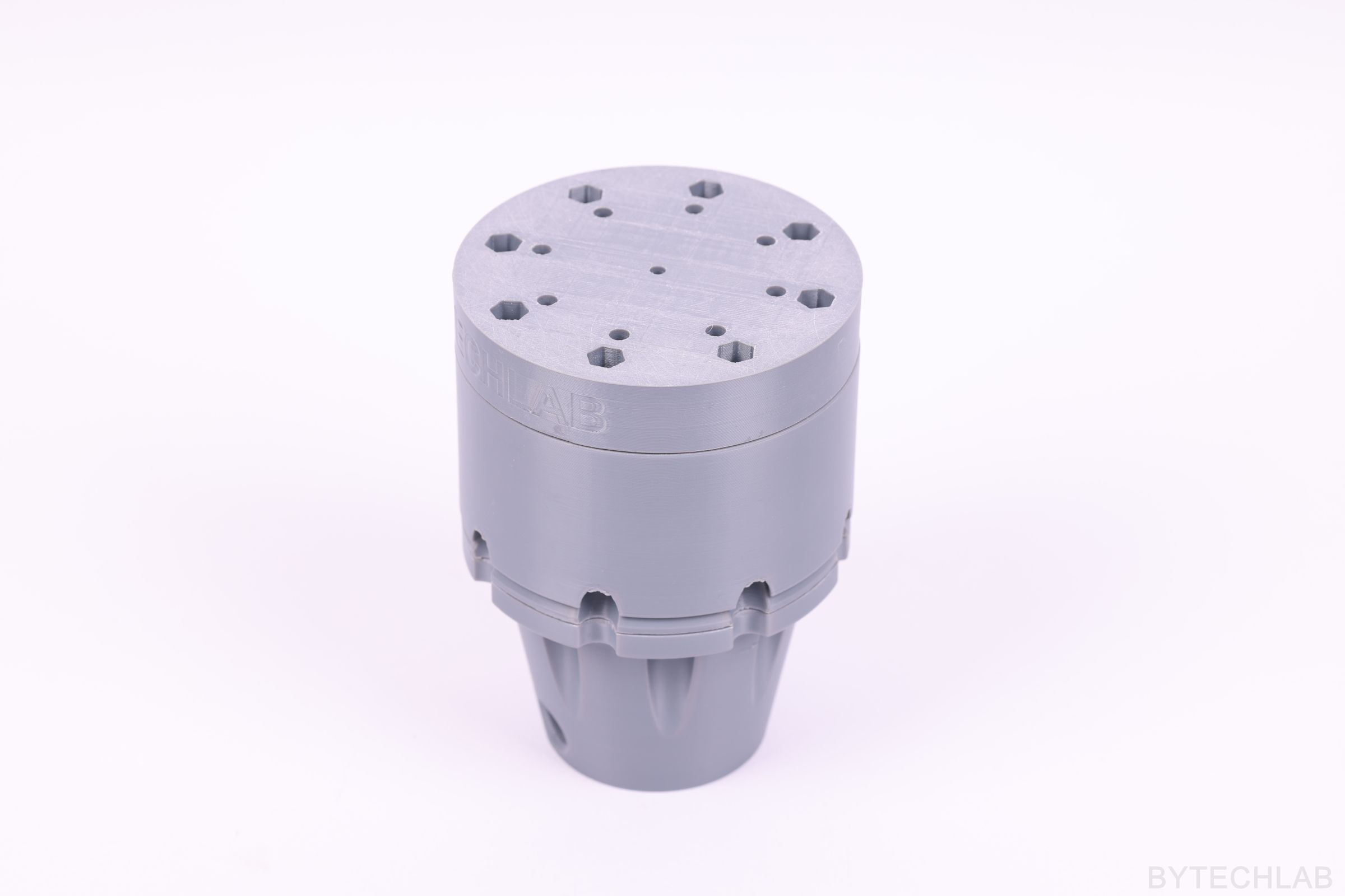
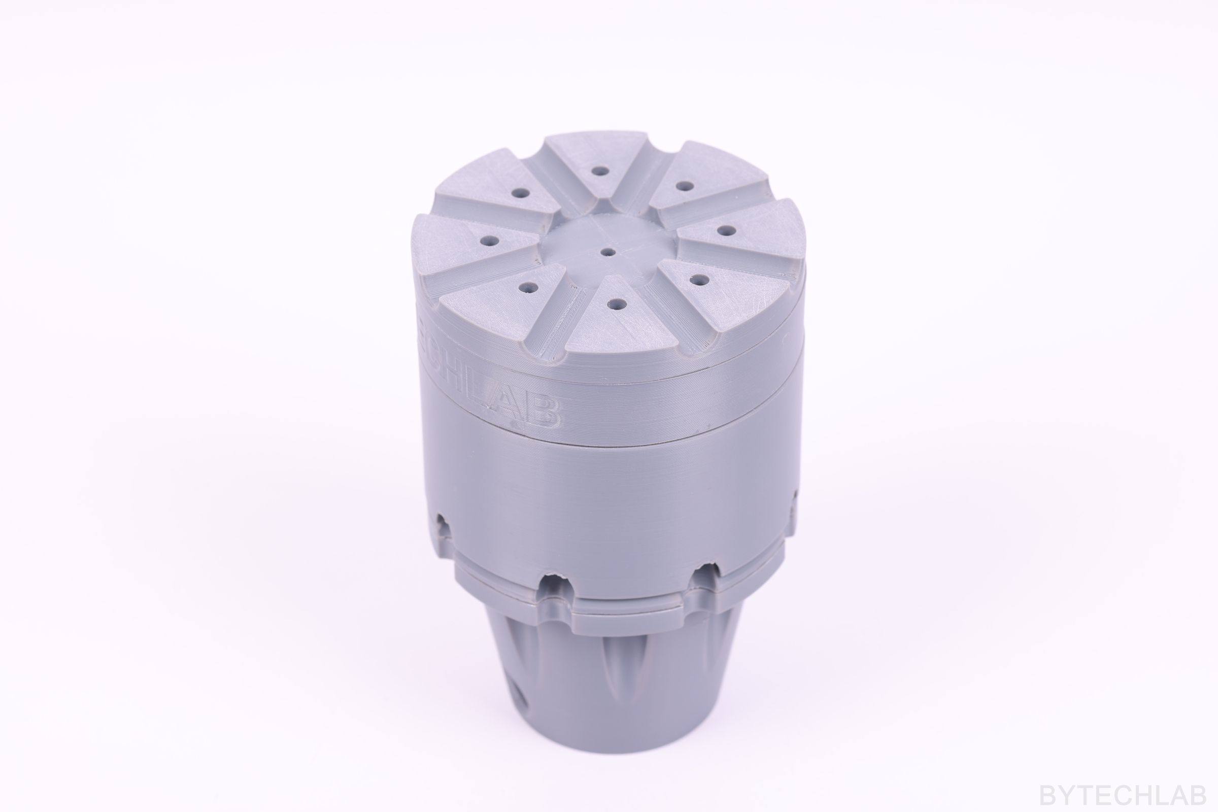
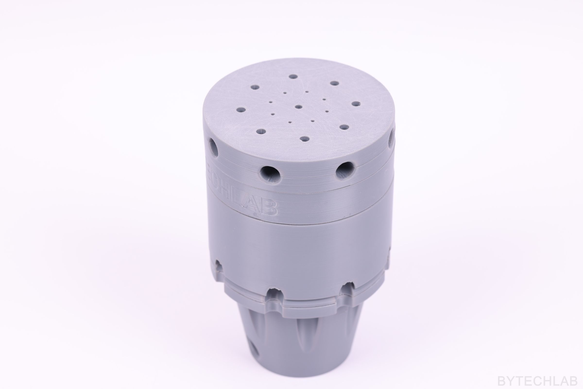
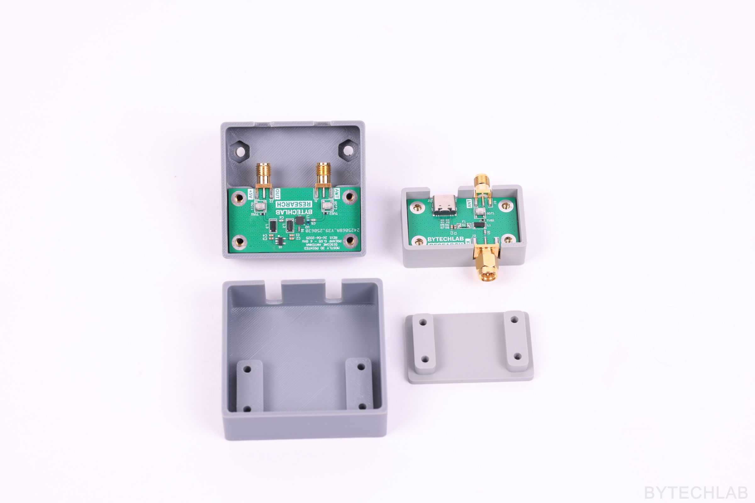
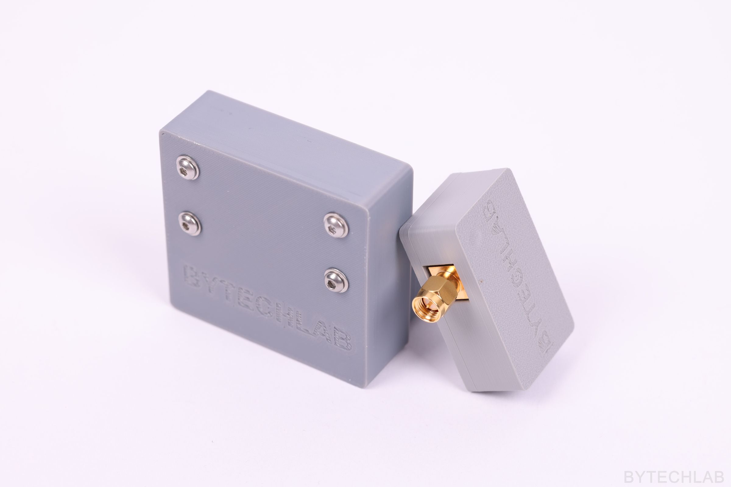
On the photos below you can see assembled preamp and bias tee PCB’s together with the 3D printed cases. The preamp case was designed in the way that basically should keep the PCB dry even during severe weather conditions.
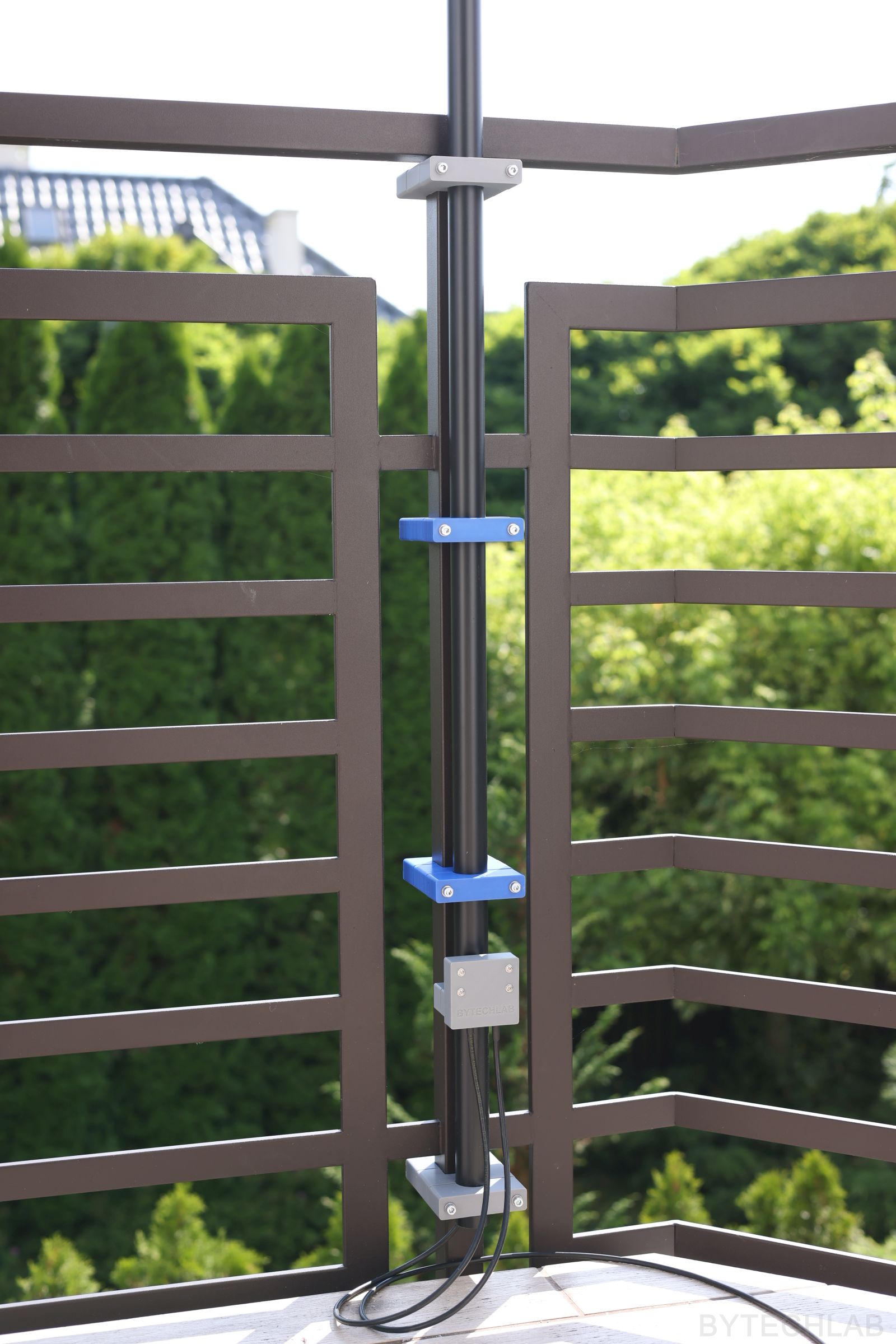
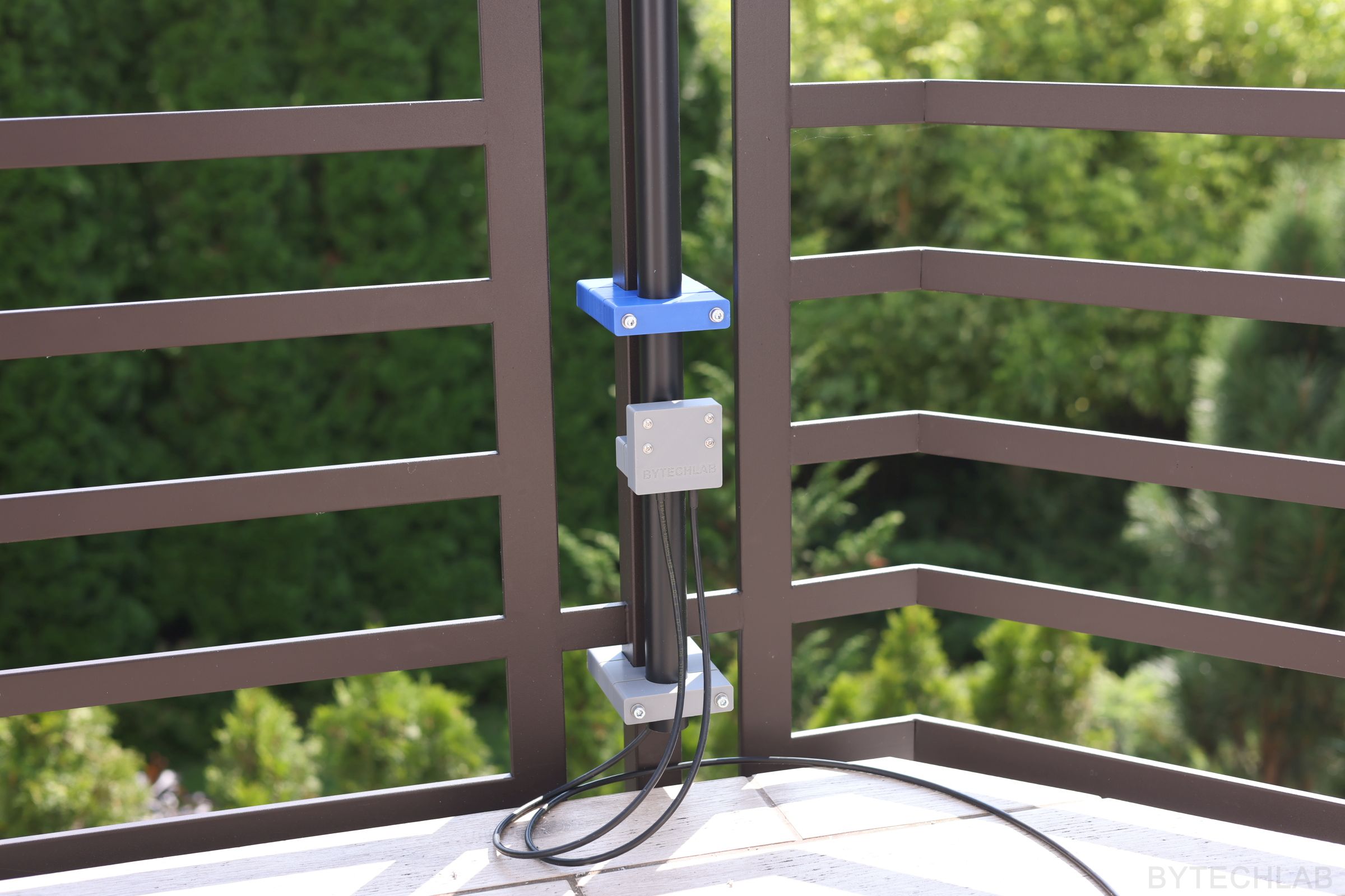
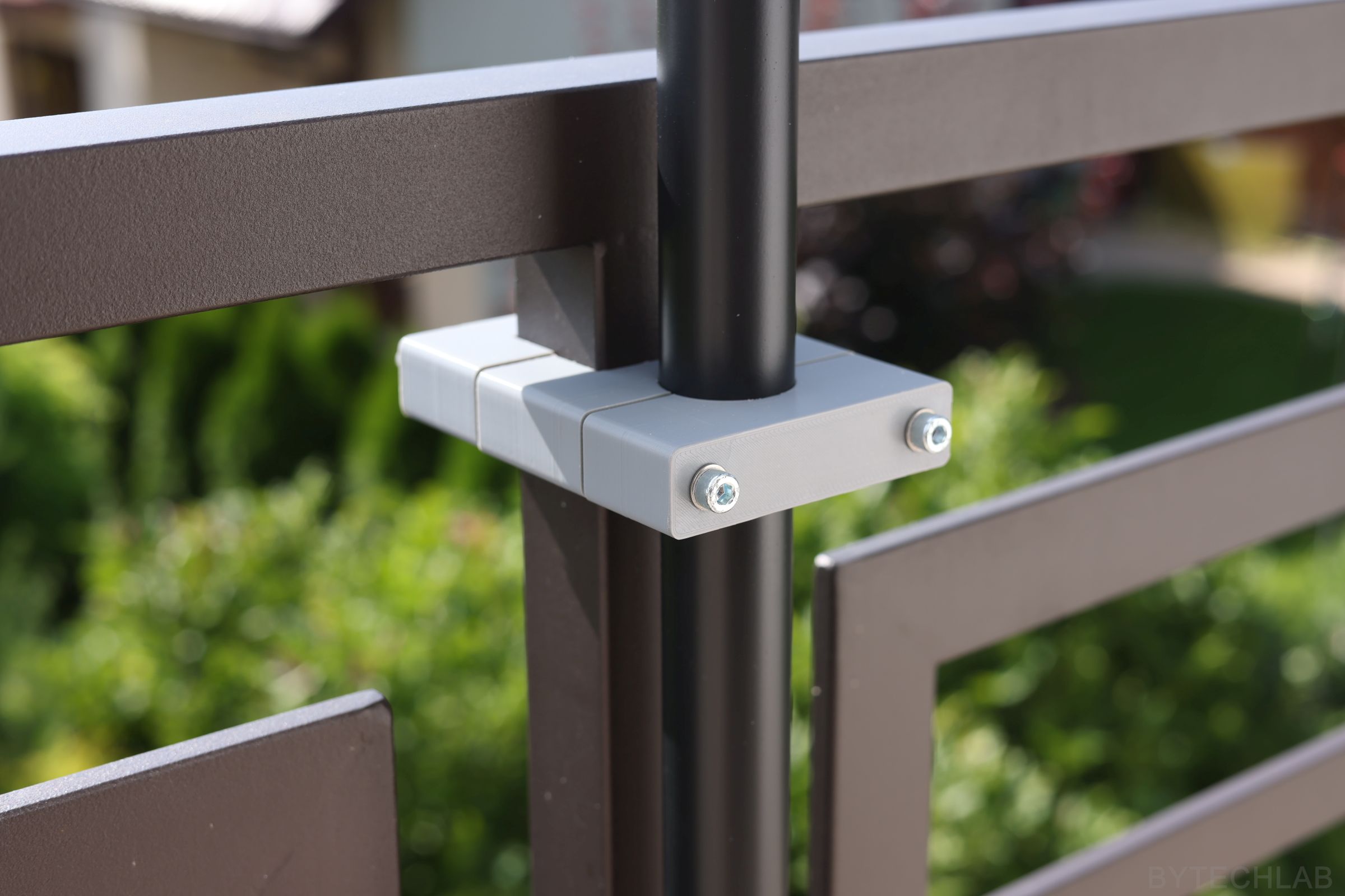
7) Mounting on the balcony
The antenna is attached to a 30 mm diameter fiberglass tube (antenna mast) which is mounted to my balcony railing with a 3D printed clamps. The preamp is mounted at the bottom to keep the coax between the antenna and preamp as short as possible. The whole setup is very rigid and should withstand high winds easily.
8) Testing
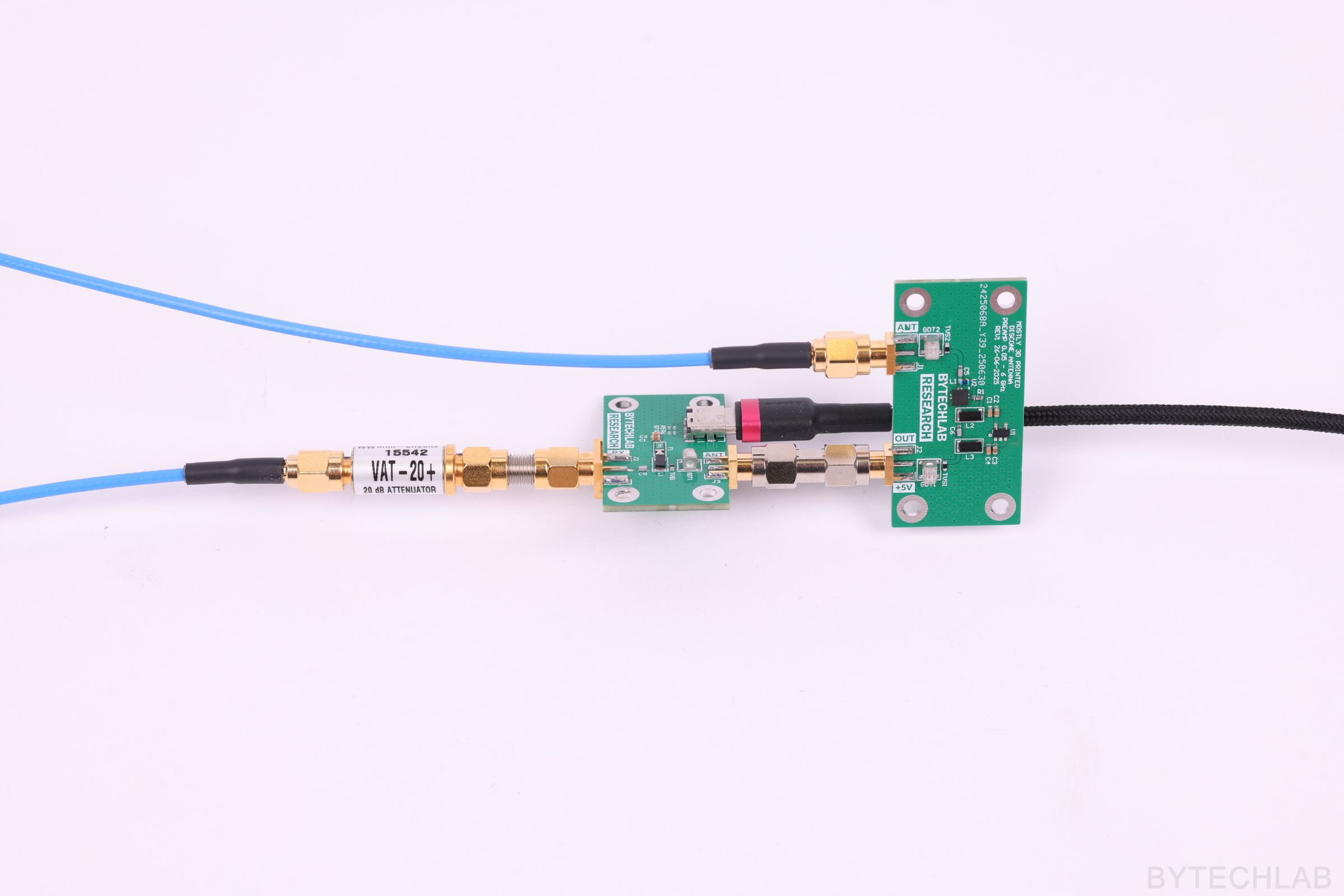
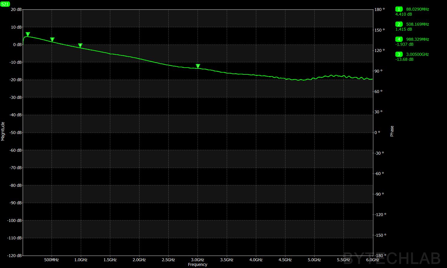
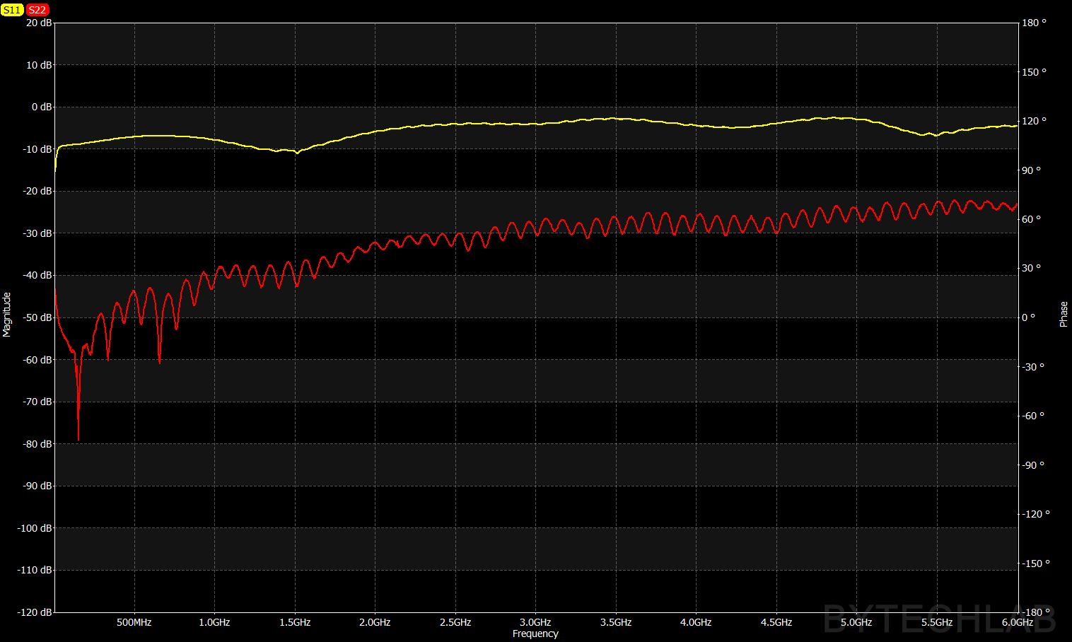
On the photo above you can see the preamp PCB and the bias tee PCB connected together for testing with a VNA. To protect the VNA I have added a 20 dB attenuator at the amplifier output. The amplifier gain is not very flat vs. frequency which is not great (I have overlooked this when I was choosing the amplifier) but it should be fine to boost the signals a little at higher frequencies. The measurements correlate with the manufacturer datasheet quite well.
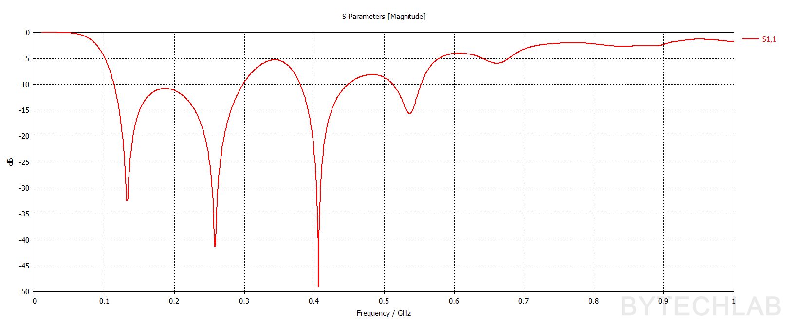
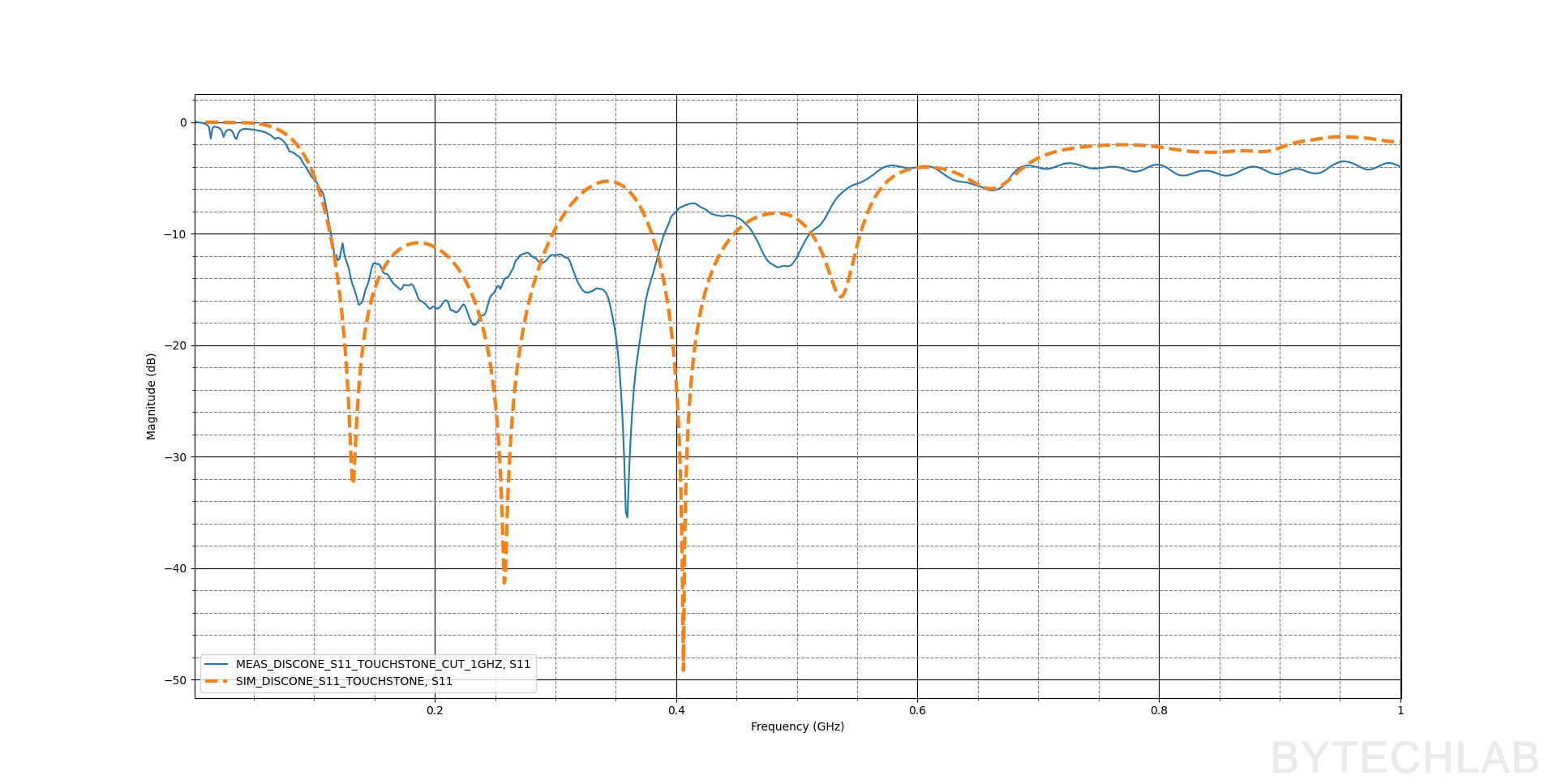
To test the antenna itself I have connected it to the VNA of course. Please note that the calibration plane was set to the end of the 2 meter long coaxial feed cable (running inside the fiberglass tube). Because of that the real |S11| should be worse than measurement at higher frequencies by about 2 times the attenuation at particular frequency. For example the attenuation at 1 GHz for RG58 CU cable that I have used is 0.56 dB/m, this means that the real |S11| might be worse by about 2 dB at 1 GHz. Even when considering the above the impedance matching is quite good from about 80 MHz to 1 GHz – ~one decade (it gets worse at higher frequencies).
On the charts below you can see that the simulation correlates with the measurement quite well. The differences might happen due to many reasons ( for example measuring this antenna next to metal balcony railing, walls etc. which influence the response).
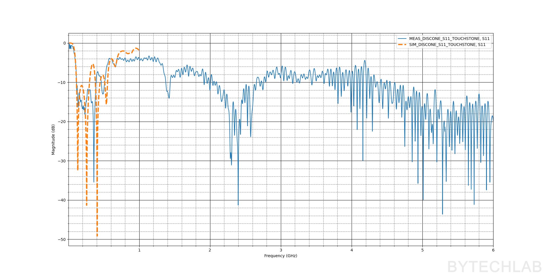
Out of curiosity I have measured the |S11| at higher frequencies (1 GHz – 6 GHz) The antenna seems to be working quite well in this range too even though it wasn’t designed or simulated for this range.
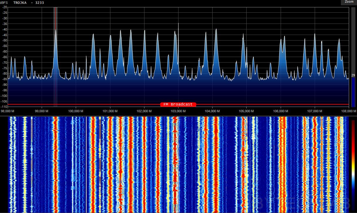
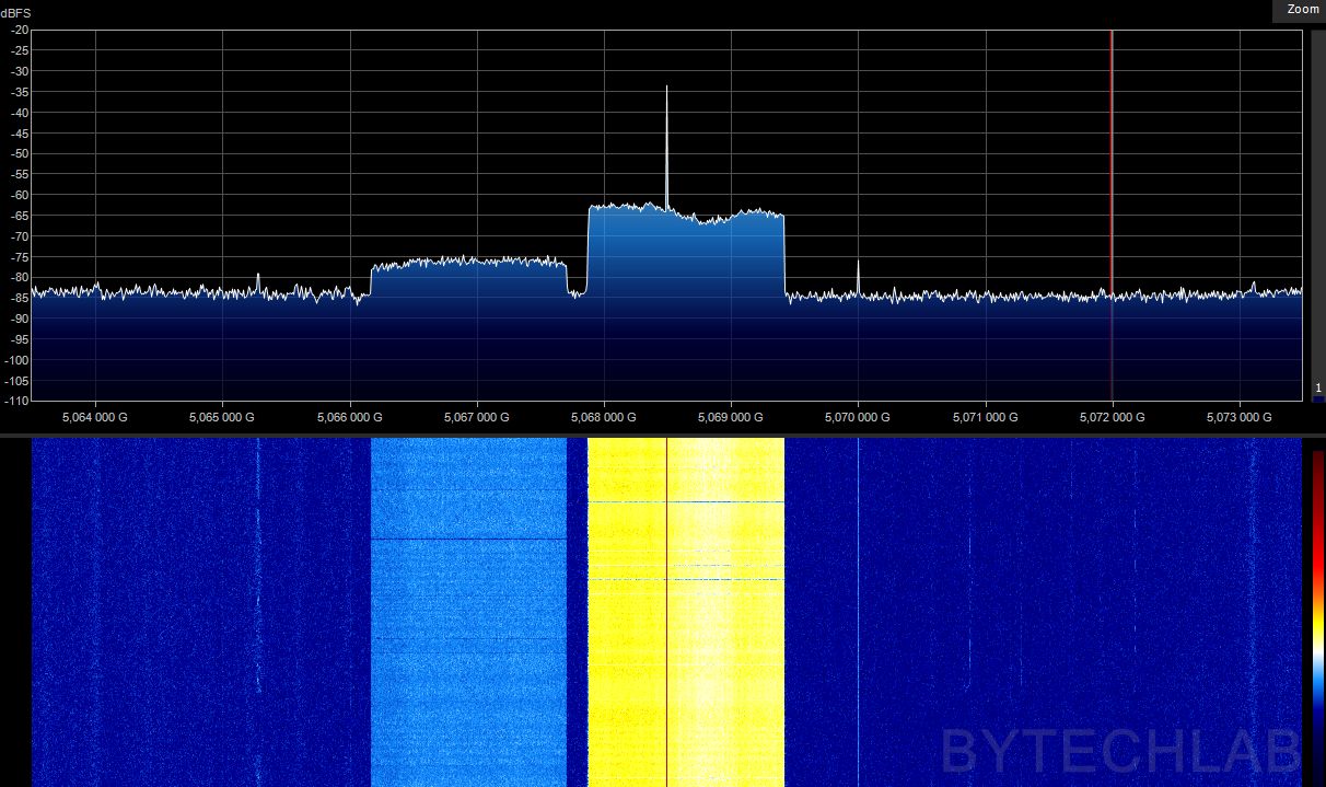
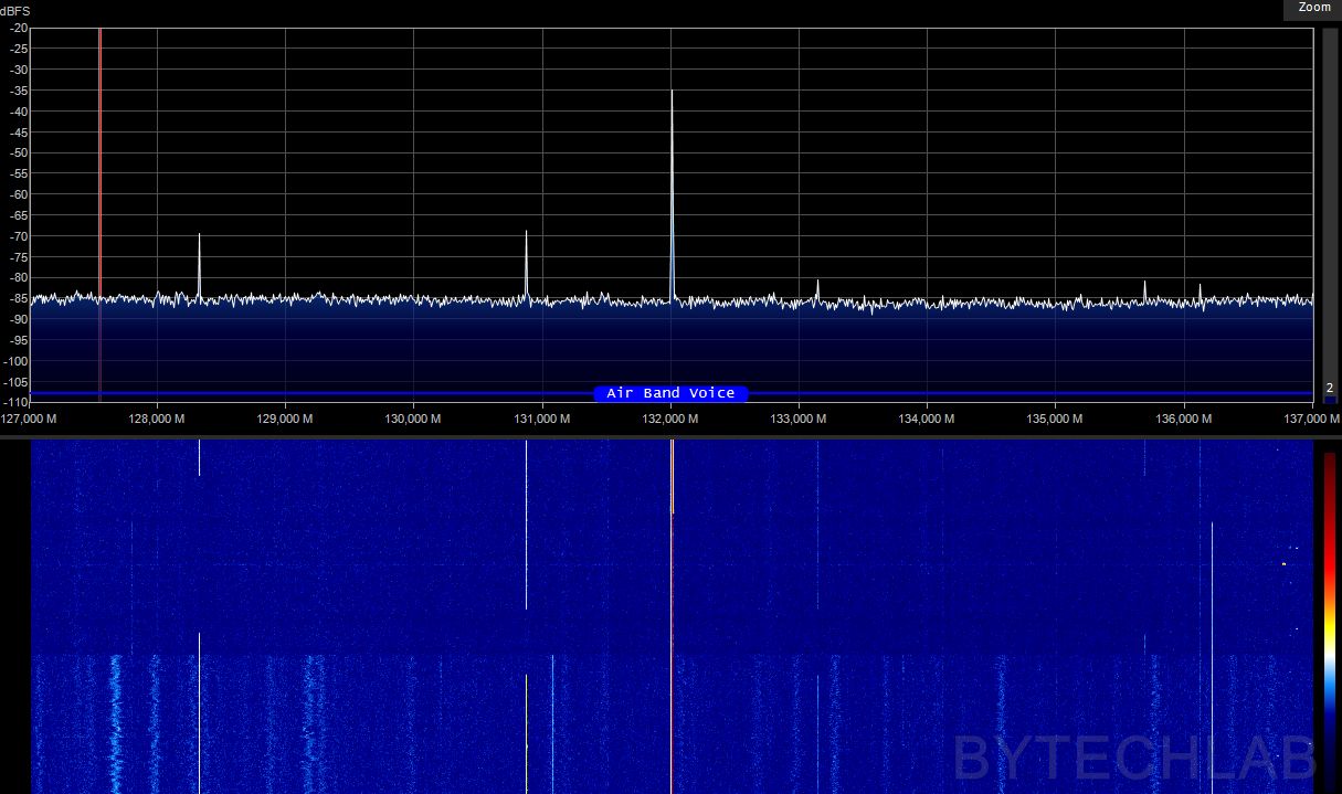
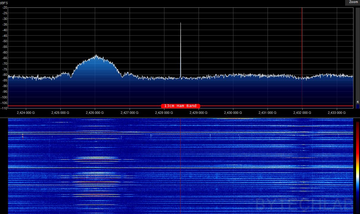
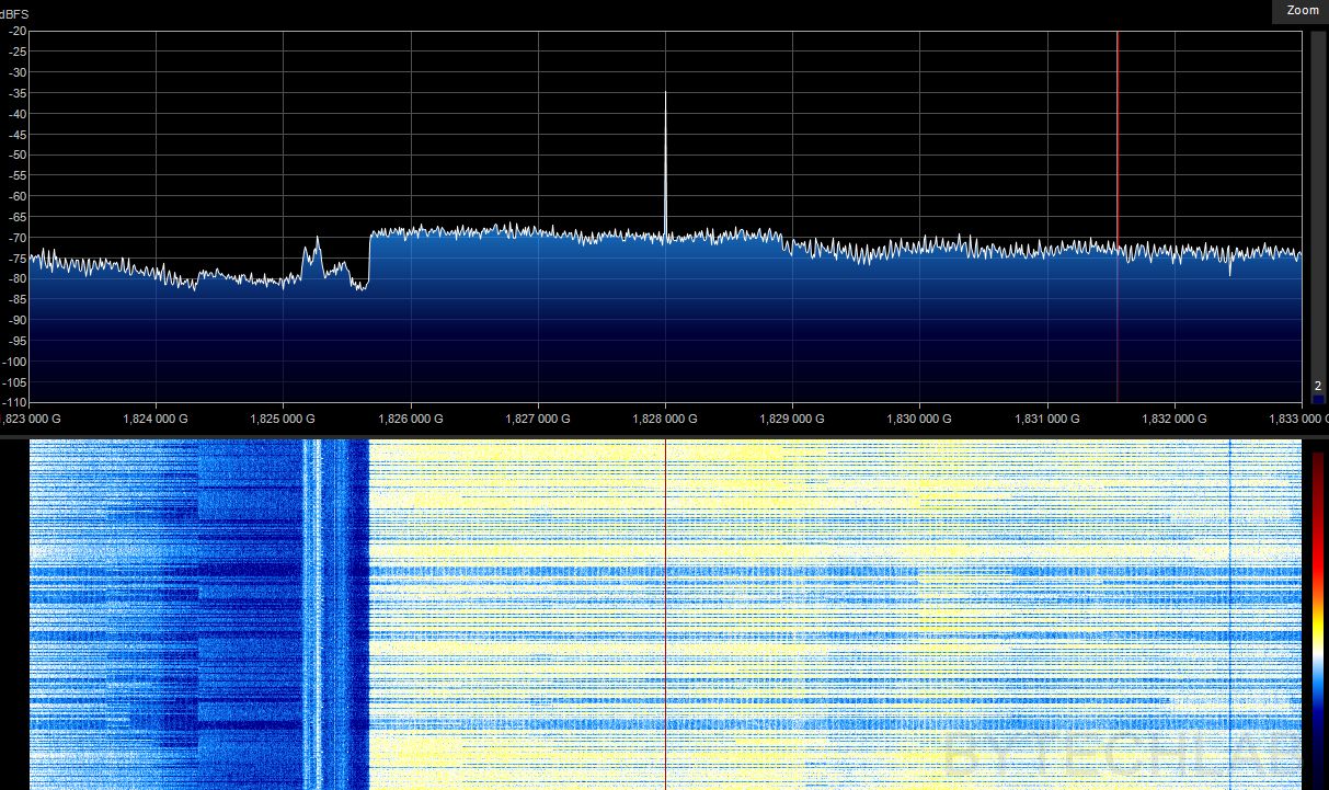
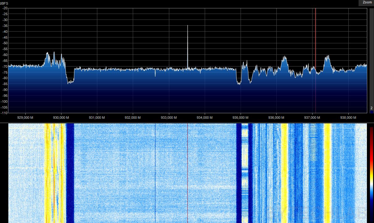
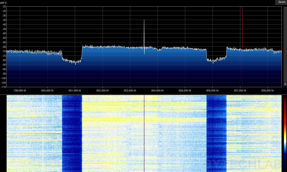
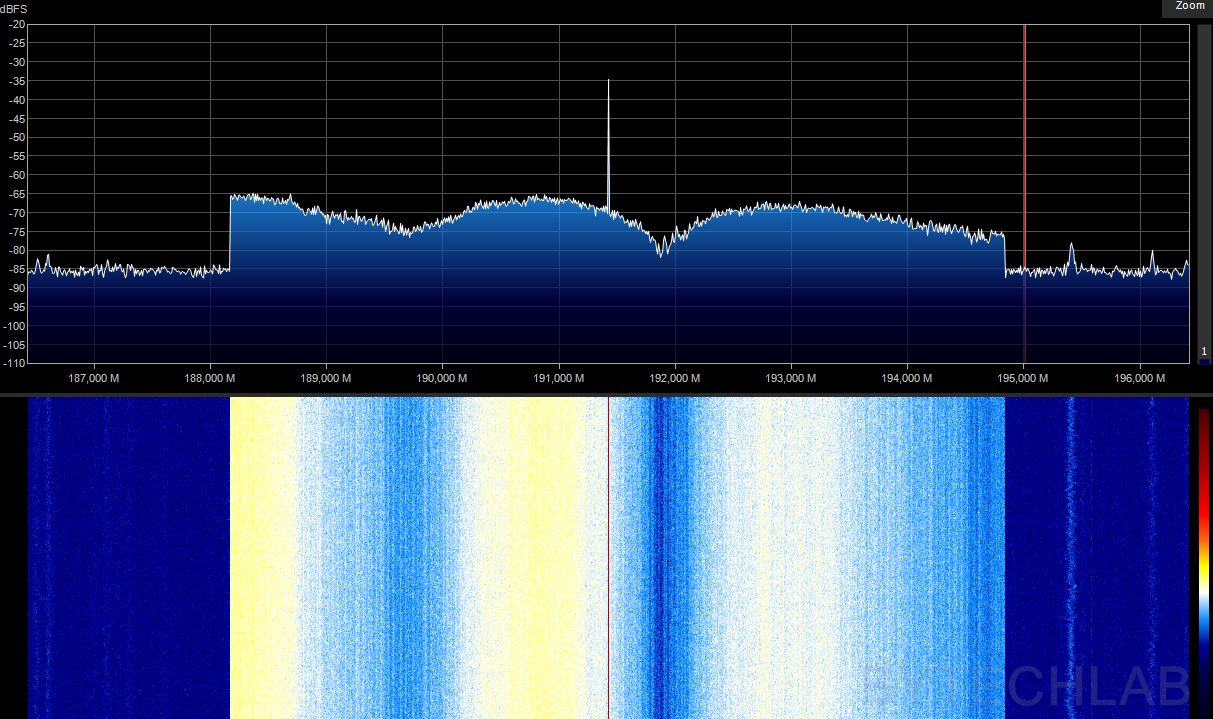
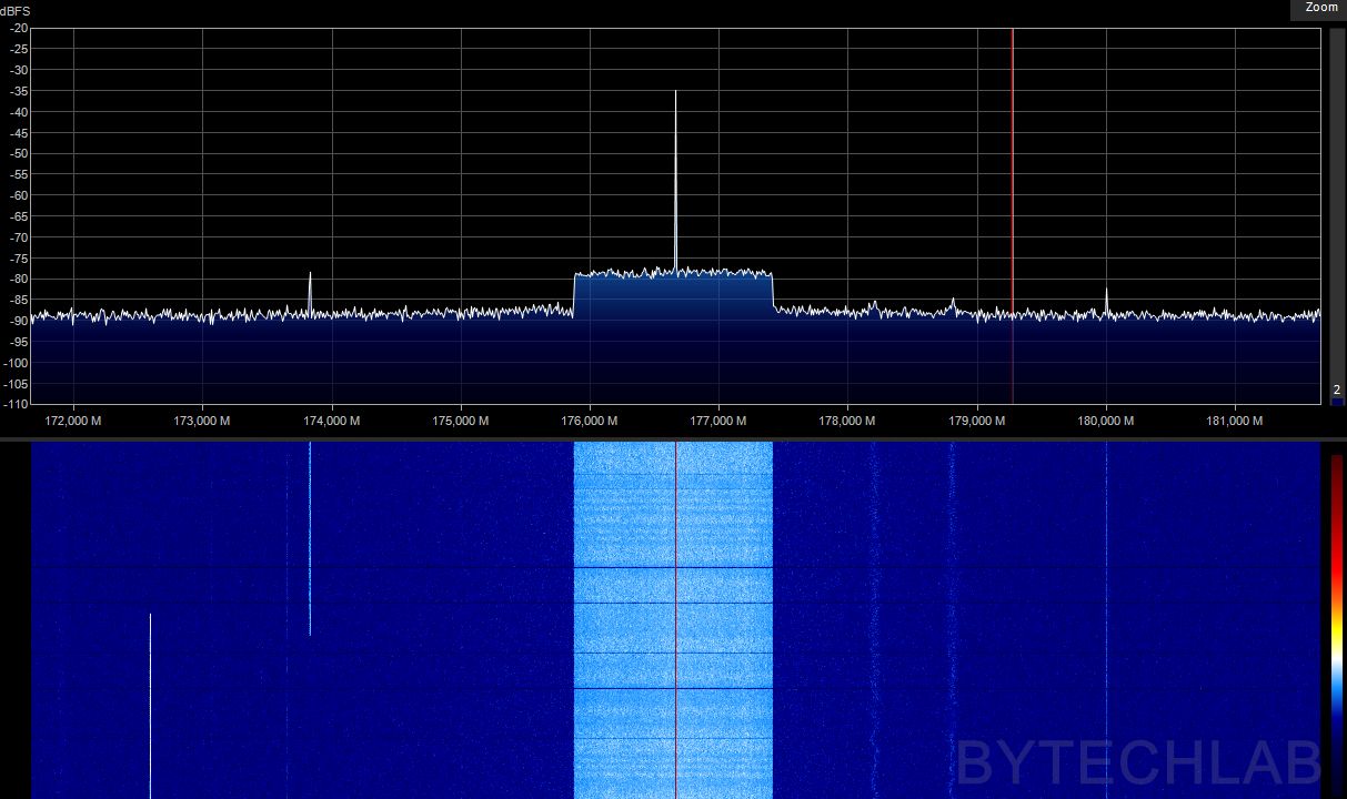
As a last step I have connected the antenna to my SDR to check what signals I can receive with this setup. It quickly came out that I can receive huge amount of signals everywhere & I haven’t found any “dead spots” on the spectrum which suggests that the antenna is working reasonably well to receive signals in the whole 80 MHz to 6 GHz range. It was quite fun to listen to some of the not encrypted signals like communication between the airplane and the tower (airband).
7) Future improvements
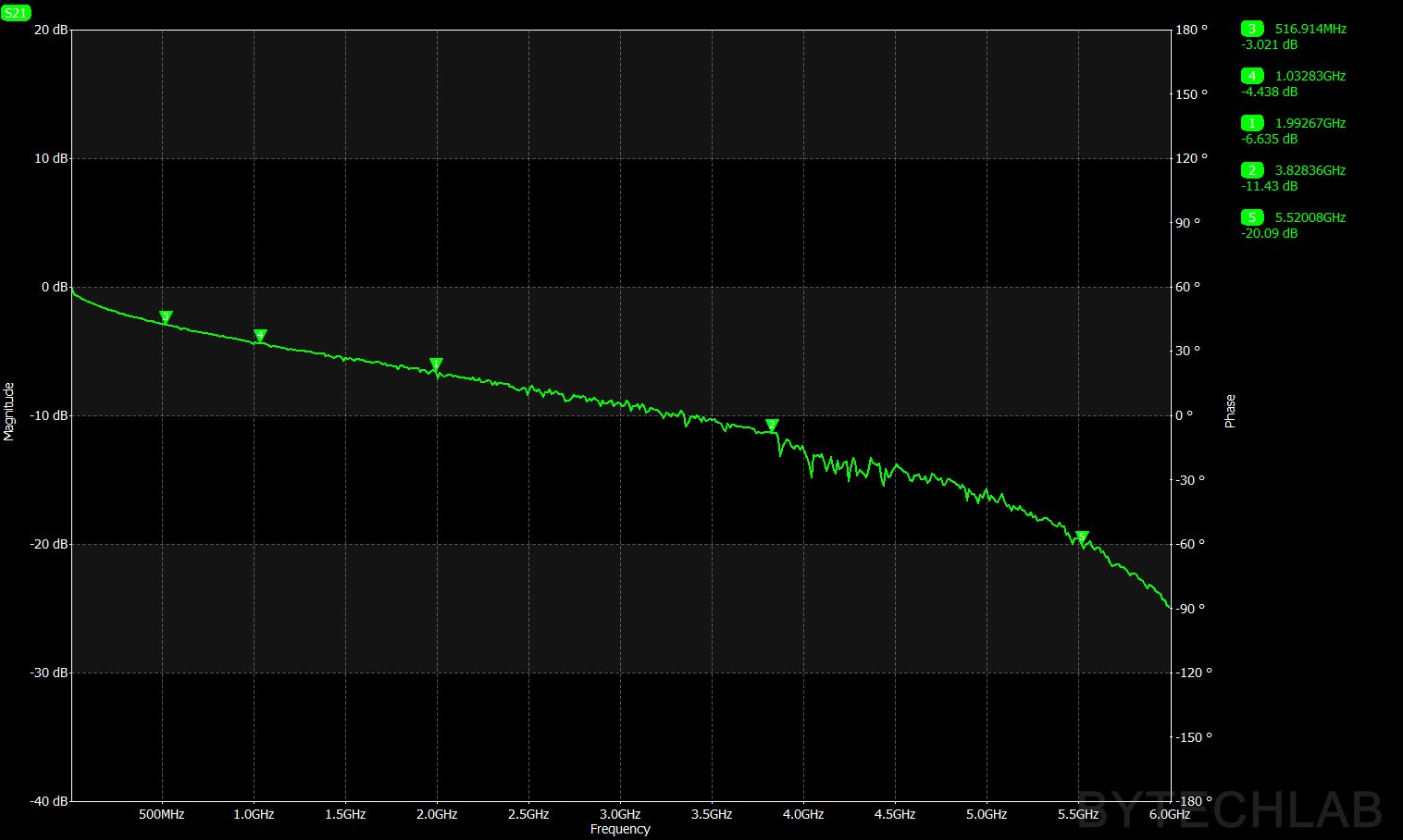
Unfortunately to connect the antenna to my SDR I had to use quite long (6-8 m) RG58CU cable which was quite cheap. Because of this the attenuation at higher frequencies is quite bad (-4.4 dB @ 1GHz, -6.7 dB @ 2GHz, -12 dB @ 4GHz etc..). This together with the lower gain of the preamp at higher frequencies is causing a lot of the signal power loss. Because of this the whole setup is less sensitive at higher frequencies.
Possible improvements:
- Swap preamp for a different one (flatter response),
- Use lower loss coaxial cable,
- Improve the antenna matching and efficiency at higher frequencies,
8) Conclusions
I’m very satisfied with the current design, there are some improvements possible but for my application it is good enough. I think that this setup will be very useful in my future projects. I have already used this antenna to receive and decode LoRa frames that were transmitted by the transceivers that I have designed.
You can read about this project also on:
- Hackaday: https://hackaday.com/2018/05/29/this-mostly-3d-printed-discone-antenna-is-ready-for-broadband-duty/
- rtl-sdr.com: https://www.rtl-sdr.com/a-discone-antenna-made-from-3d-printed-parts-and-aluminum-rods/