
This DIY Bowl Feeder is a part of SMD parts sorting machine. You must be wondering, why I need this fancy bowl shaped thing with a electromagnet under it. The main goal is to sort SMD parts (capacitors and resistors) by their shape and size. When leaving this feeder, these SMD parts will be arranged one by one in a single line (in a “queue”), which is a good thing (it will help with the further processing of these parts in the rest of the machine to which this feeder will be connected).
But wait, there’s even more! Finished feeder will have many stages and it will be much more complex (SMD parts that don’t match the exact pattern will drop down to the next bowl feeder).
You can put all of the SMD parts you have into the main feeder and on the other side you will get them sorted by size (for ex:1206,0805) and arranged one by one in a proper way.
This is just a “proof of concept” prototype. Below I will describe how I designed the whole device and how it works:
BOWL FEEDER DESIGN & ASSEMBLY
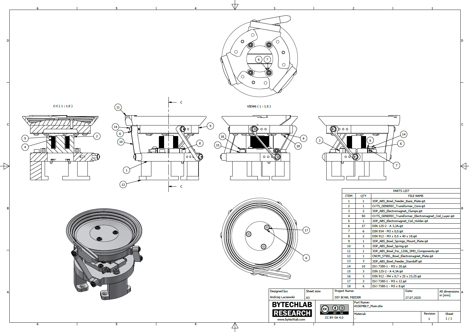
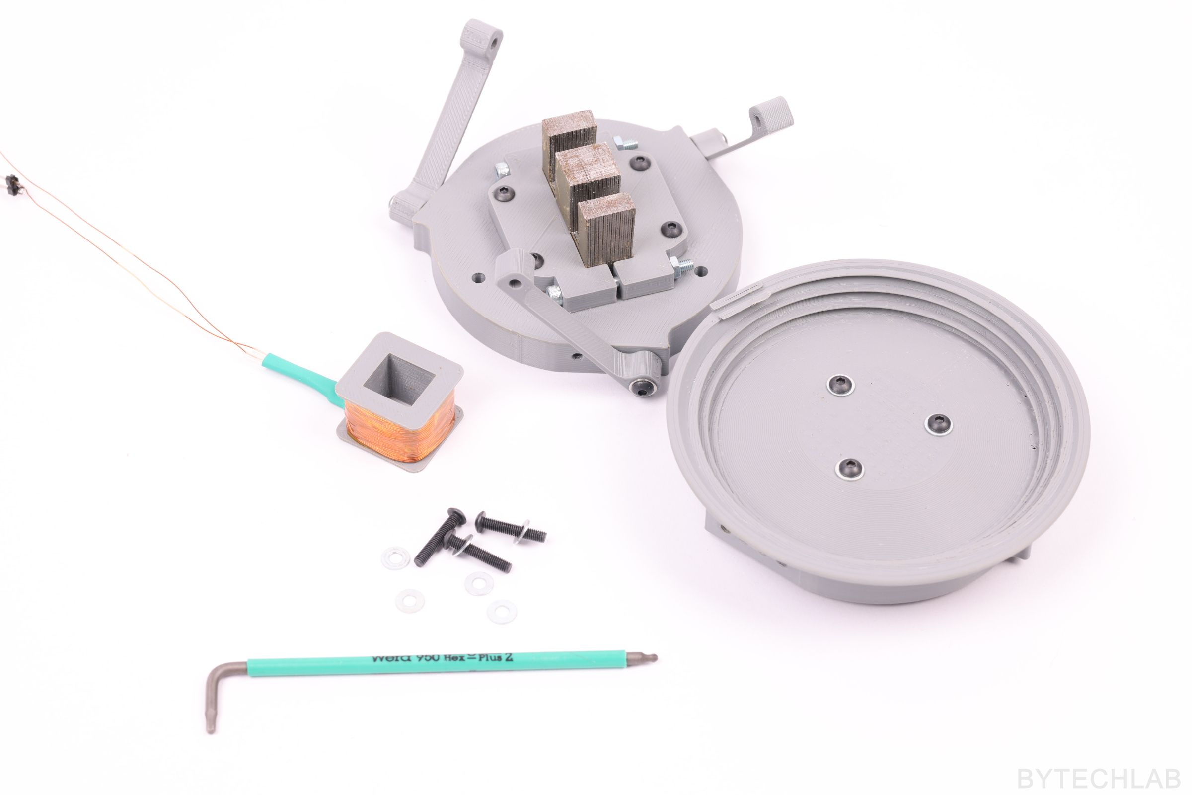
I didn’t have an idea for the name of some 3D printed parts, so I named them as follows:
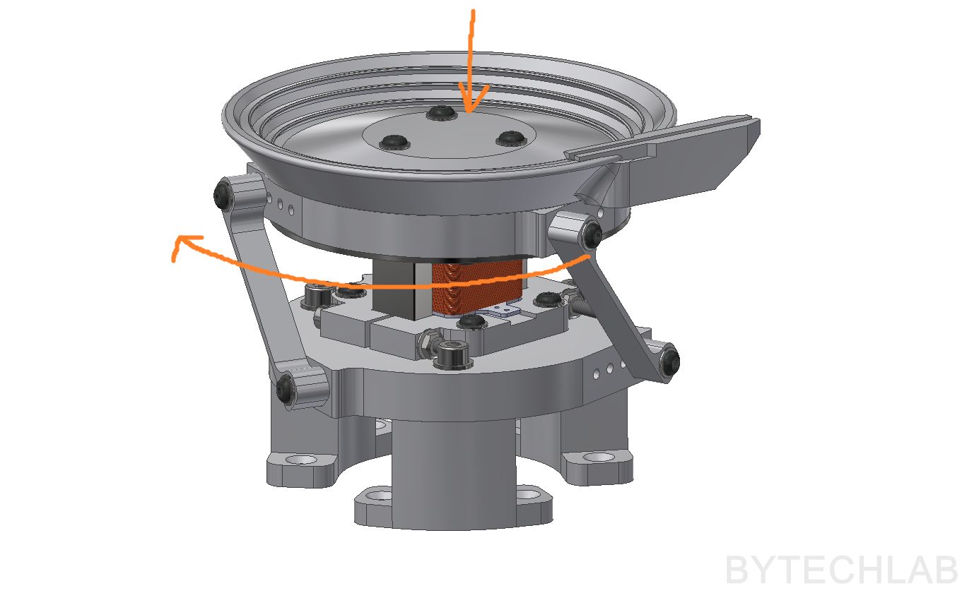
- Upper part that connects the springs together with the bowl itself – ”bowl spring mount plate”
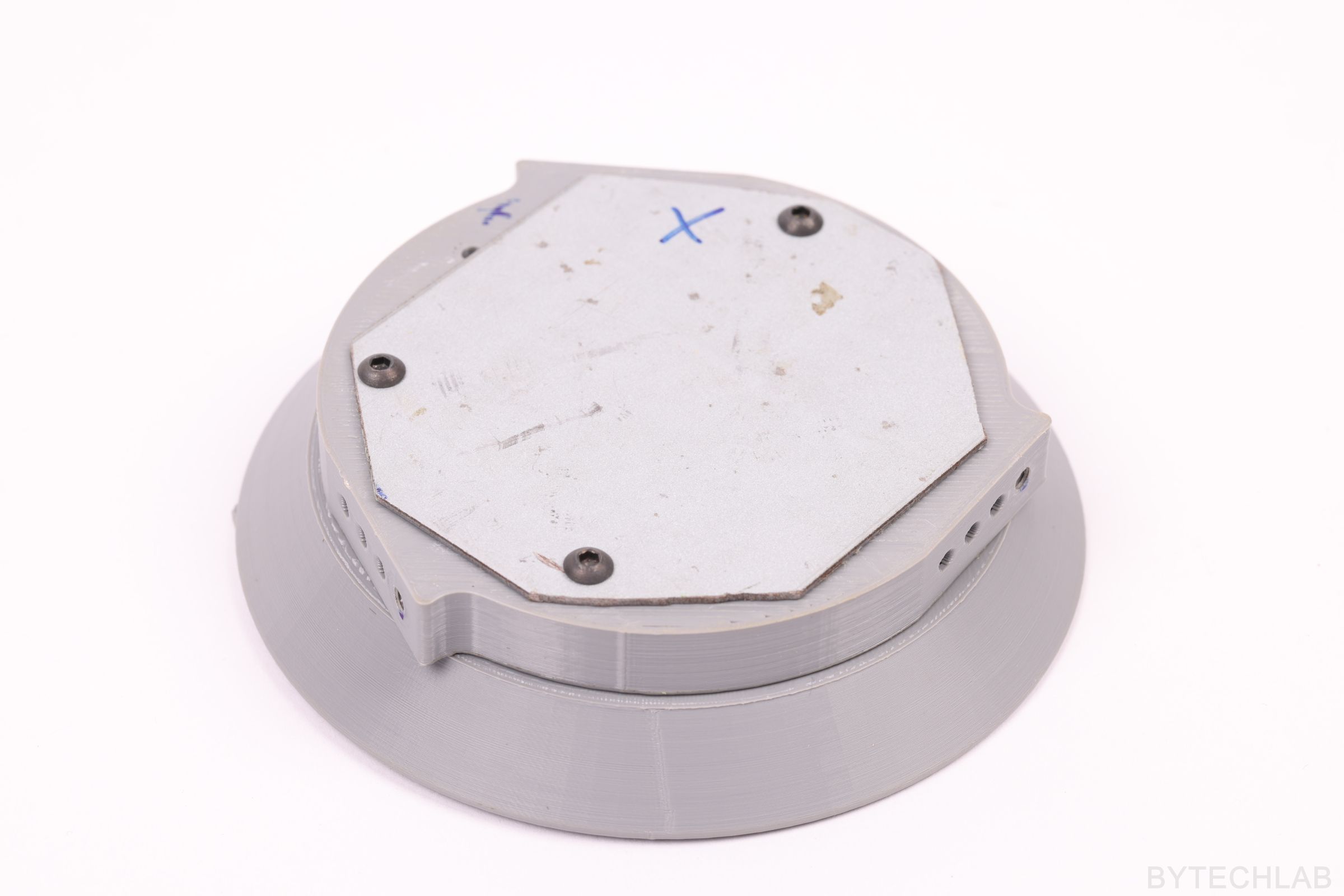
- Bottom part that connects the springs and electromagnet together – ”base plate”
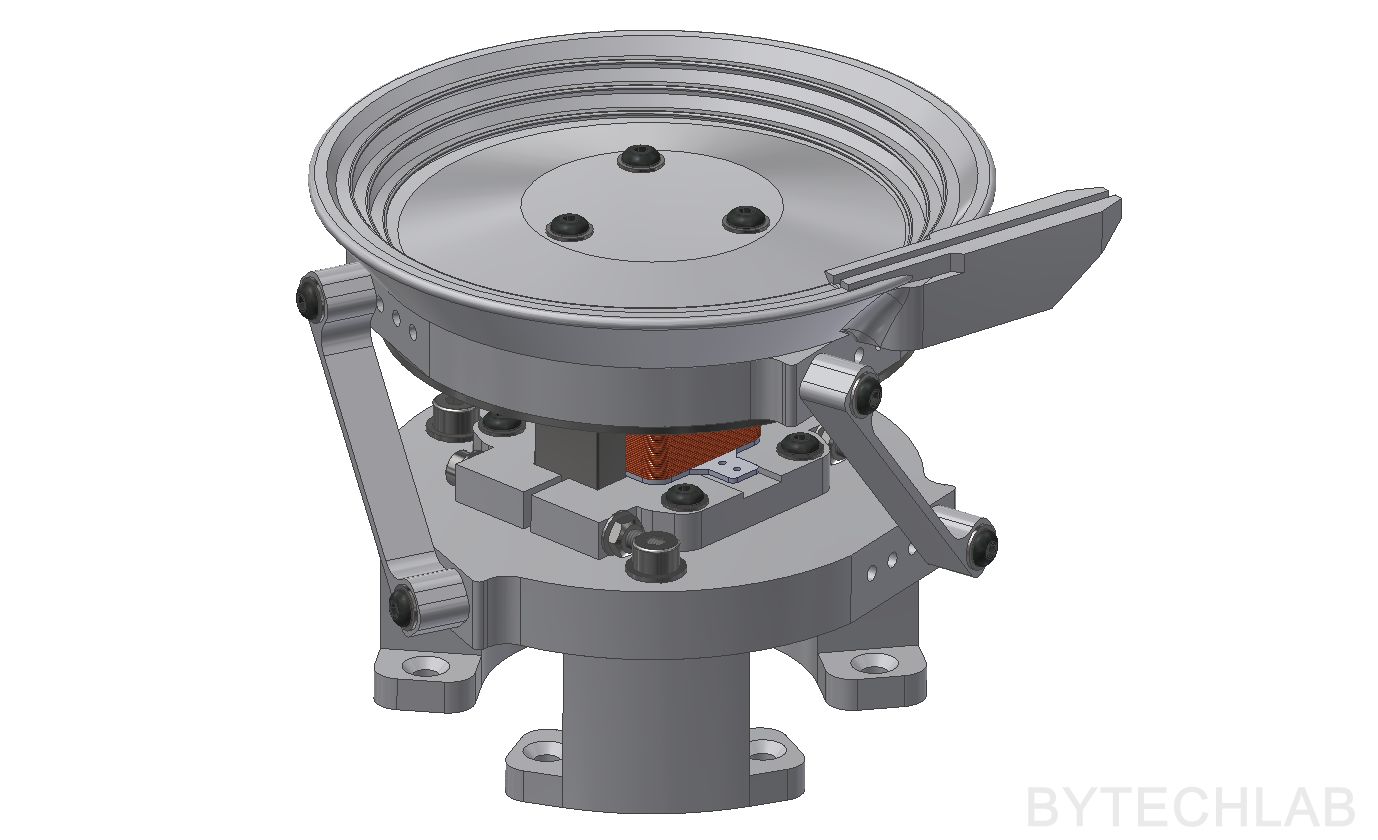
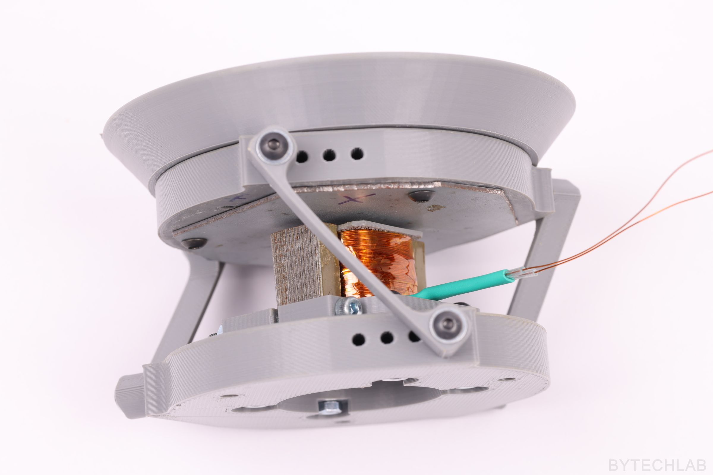
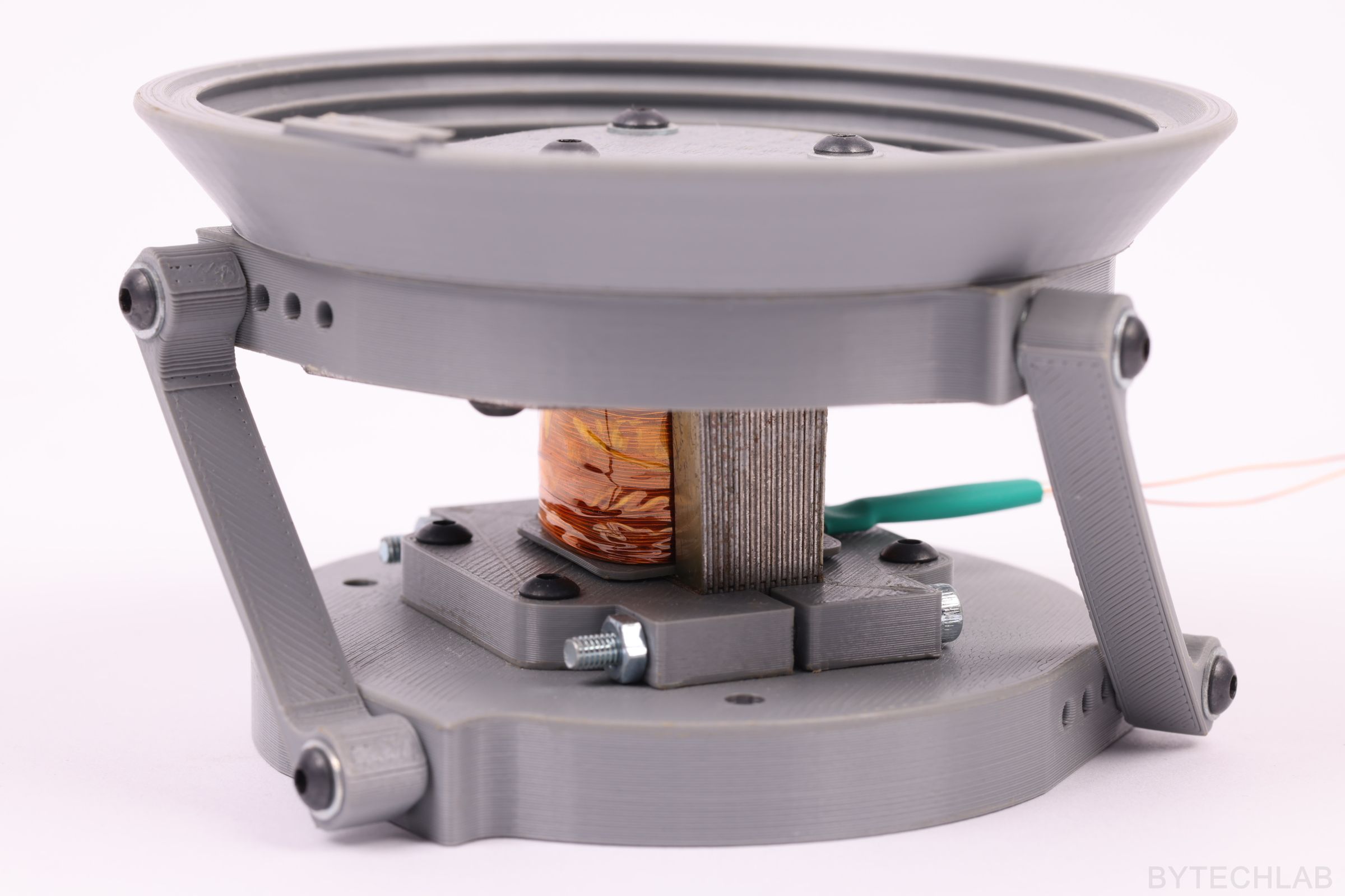
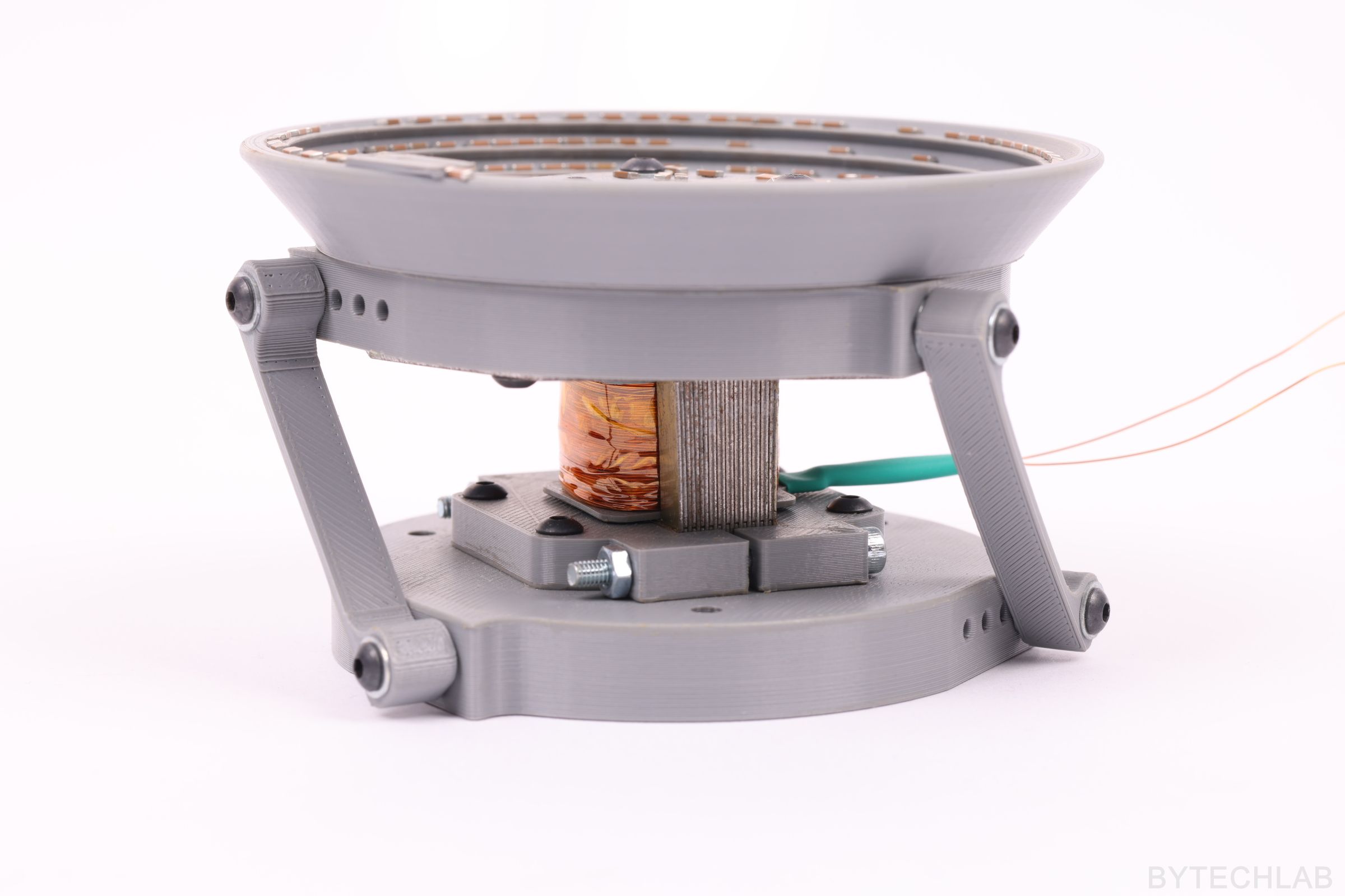
As always, everything was designed in the Autodesk Inventor software. Just before making the first prototype, I’ve carried out several simulations to make sure that the springs are designed and arranged correctly. The springs were printed from ABS filament in such a way that they can bend repeatedly without damaging (material fatigue). Their hardness, length and angle under which they are bolted down, have been chosen experimentally (that’s why there are several holes in the base plate and in the bowl spring mount plate).
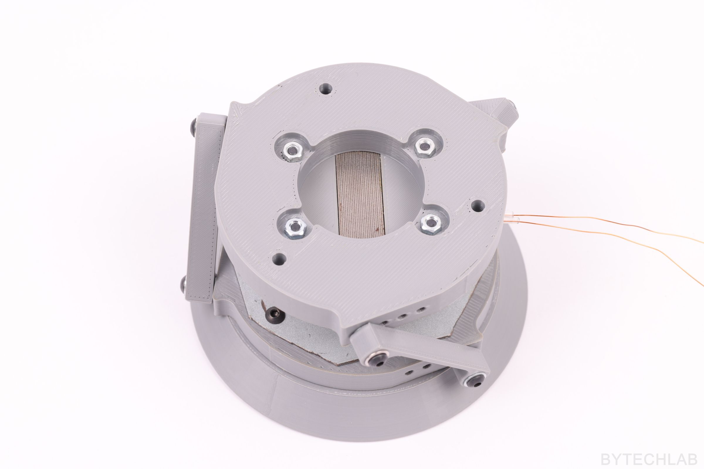
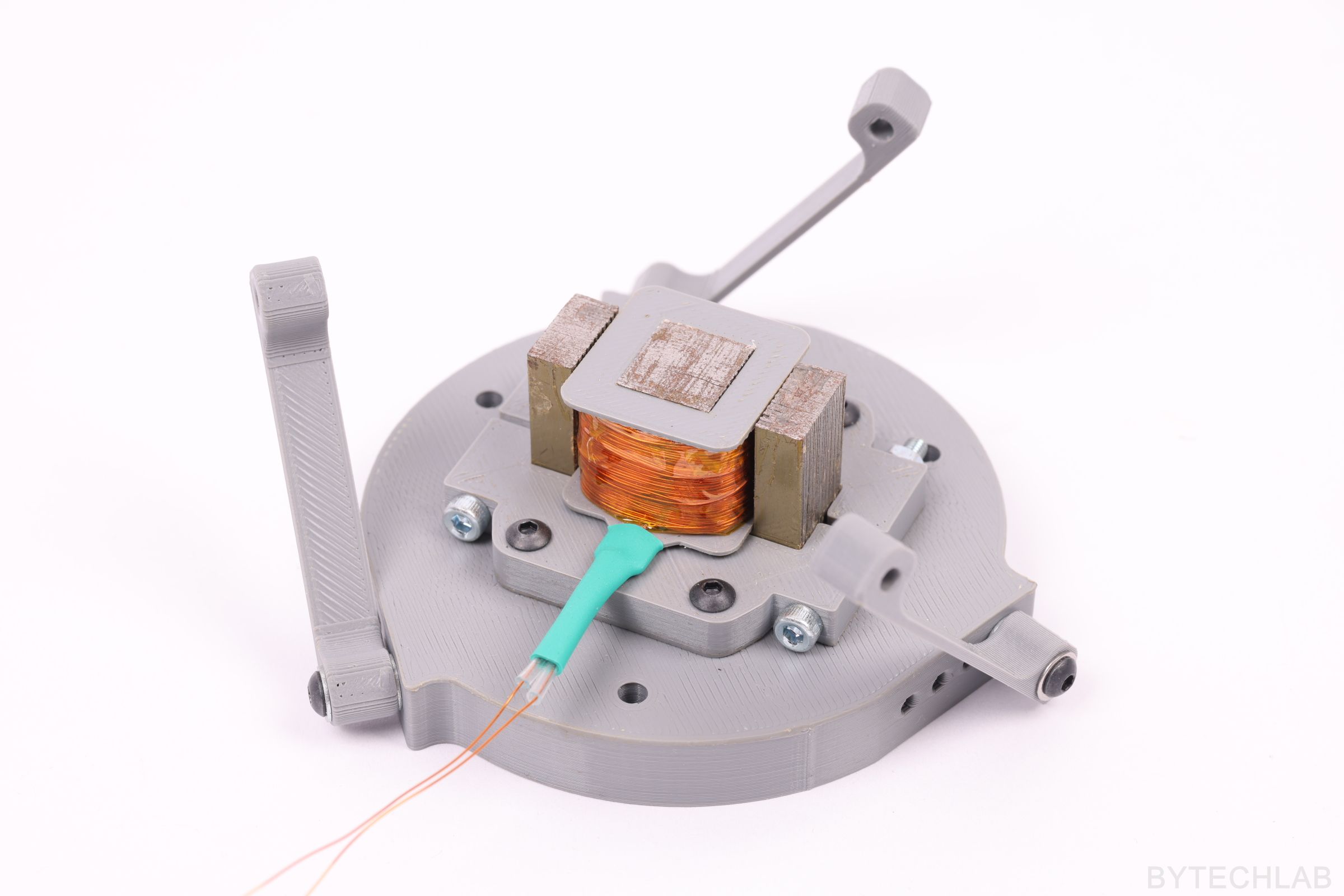
The electromagnet is attached to the base plate with two clamps that squeeze the transformer core. These clamps are bolted down to this base plate with four M3 bolts. The base plate is bolted down to the stiff surface with three M4 screws. The springs are rigidly fixed to both mounting plates using M3 screws and several washers (spring can’t rotate along the axis of the bolt).
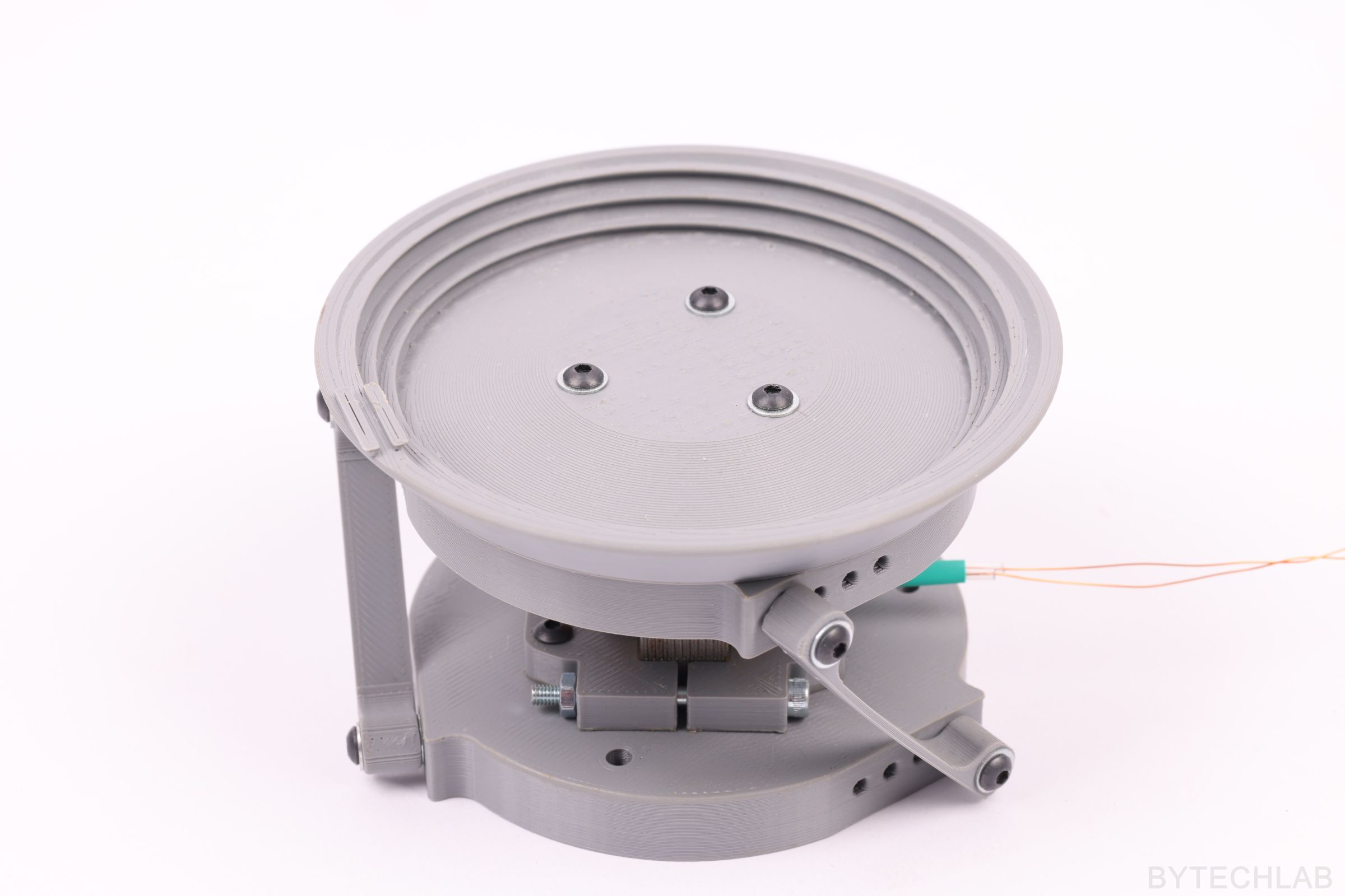
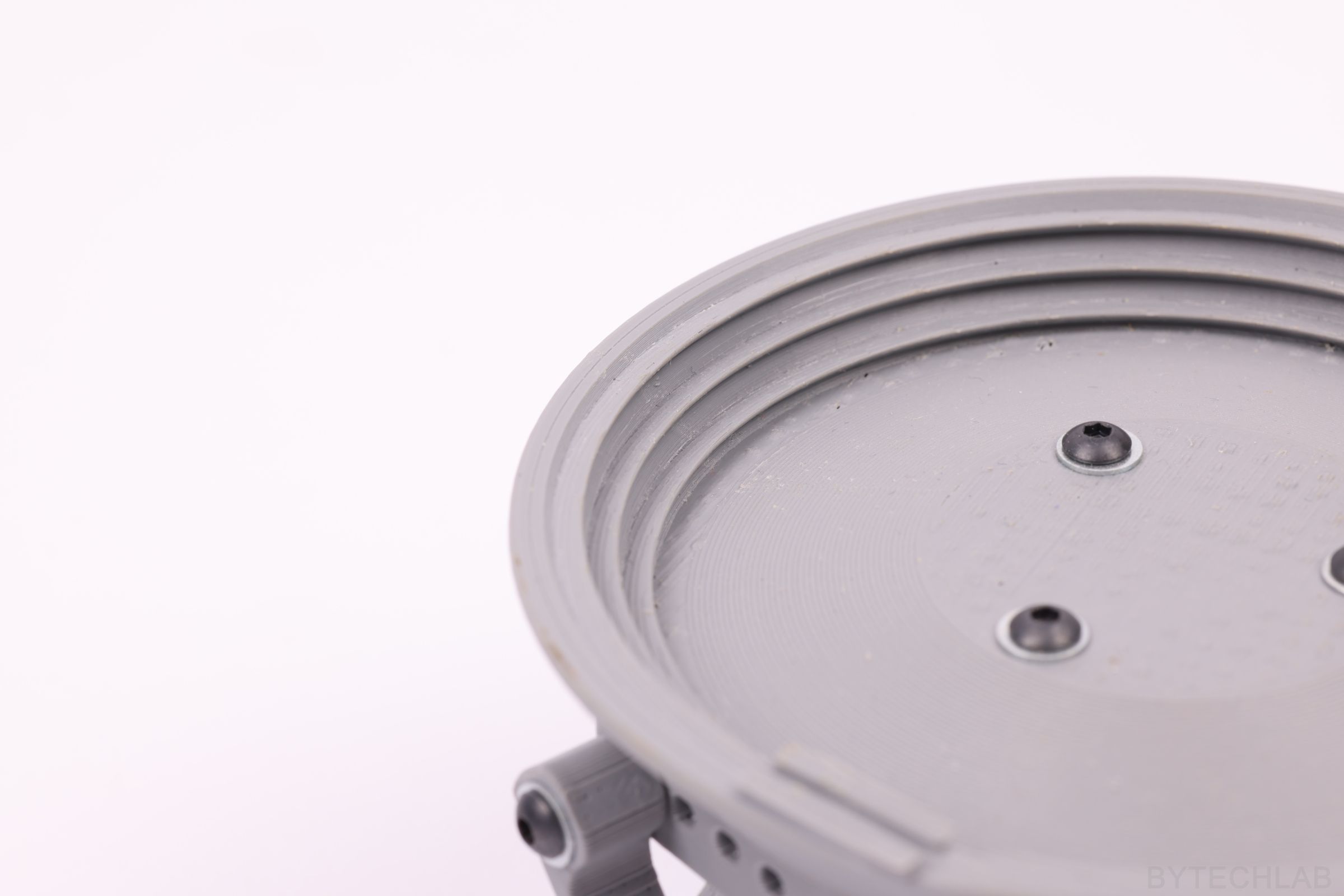
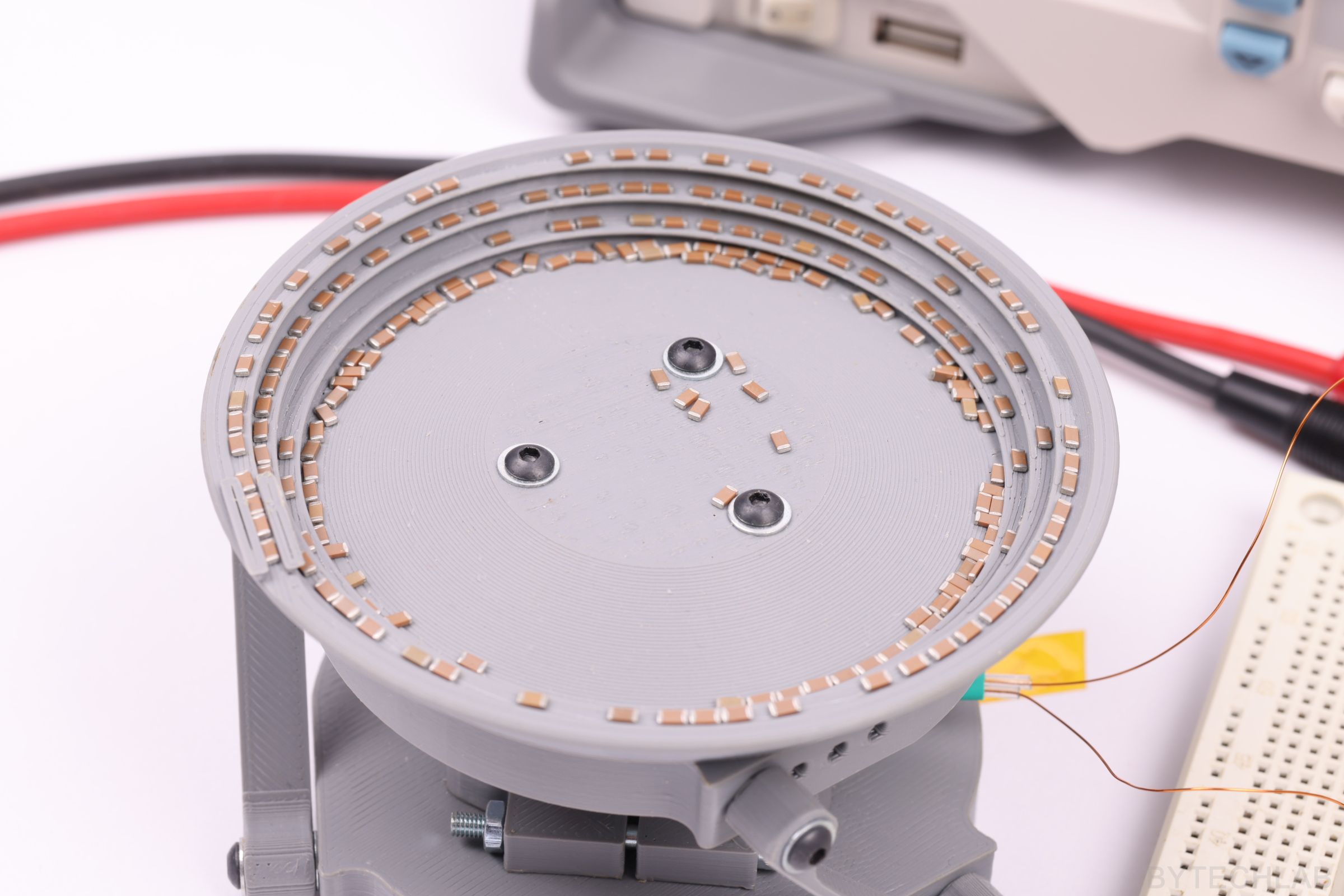
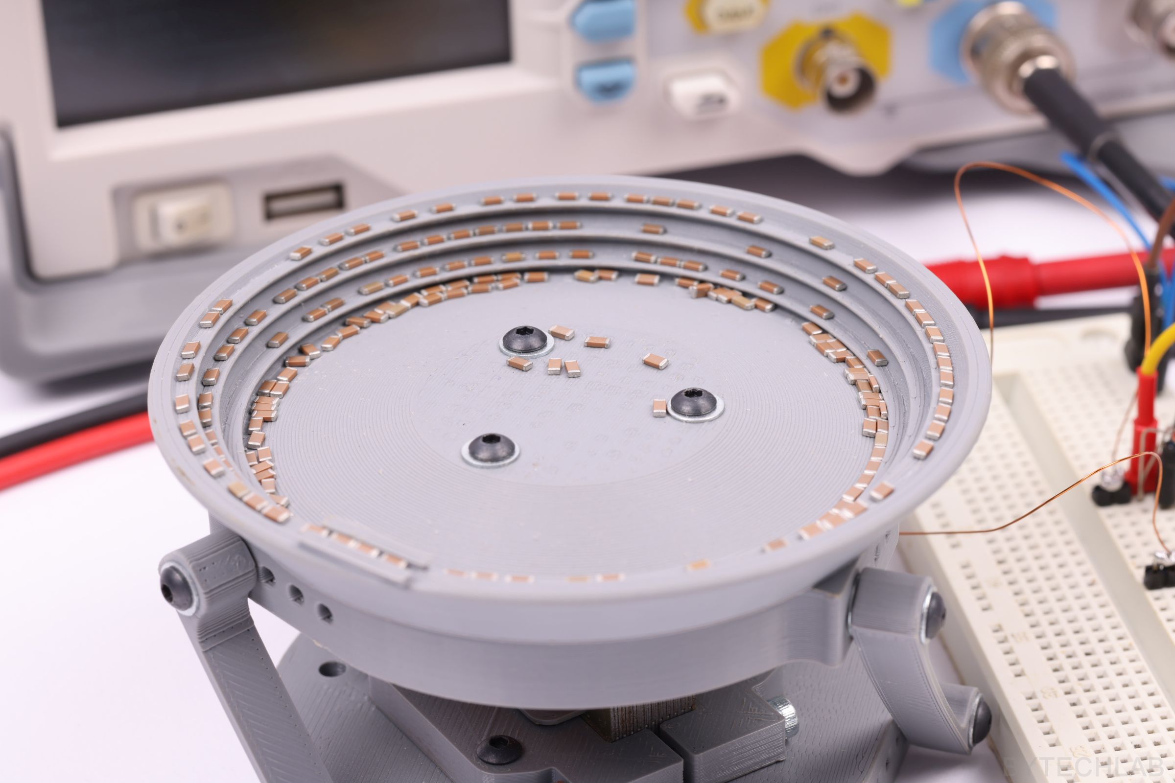
A steel plate which is pulled down by the electromagnet is attached to the bowl spring mount plate with some M3 bolts. The bowl is bolted down to the bowl spring mount plate with three M3 screws. At the very top of the bowl I have modeled the outlet channel in which the pre-sorted elements will move. In this channel, there will be an optocoupler sensor which will detect the presence of these parts. It will allow to feed only one part at a time for further processing by the rest of the machine.
The spiral on which the parts move is slightly inclined to the inside of the bowl so that the elements don’t fall down by themselves (about 10 degrees from the base of the bowl). The bowl helix pitch has been selected experimentally (when the pitch is too high the parts won’t climb up the helix). In the final version of this device I will be add some barriers and obstacles on the helix that will cause the SMD parts to drop down when they don’t match the correct size.
In the GitHub repository (MCAD folder) you can find the following files:
- Autodesk Inventor project,
- Exported STL files for 3D printing,
- Exported STEP file of the whole assembly,
- Exported PDF file with assembly drawing, BOM and assembly instructions,
- Exported assembly renders,

3D PRINTING PARTS
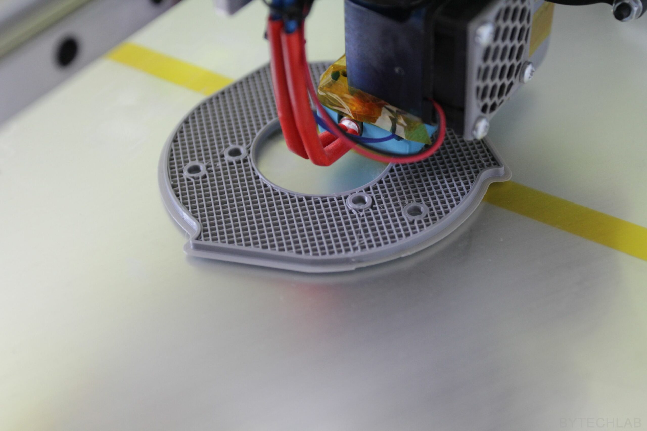
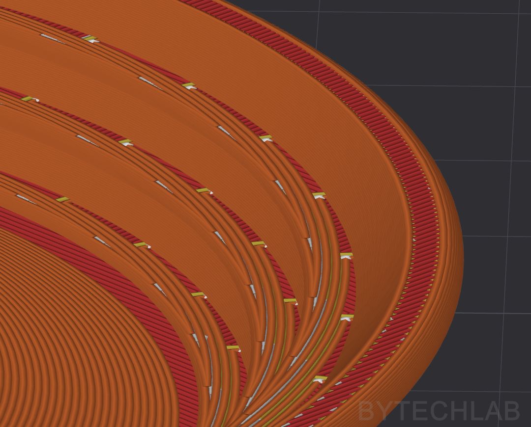
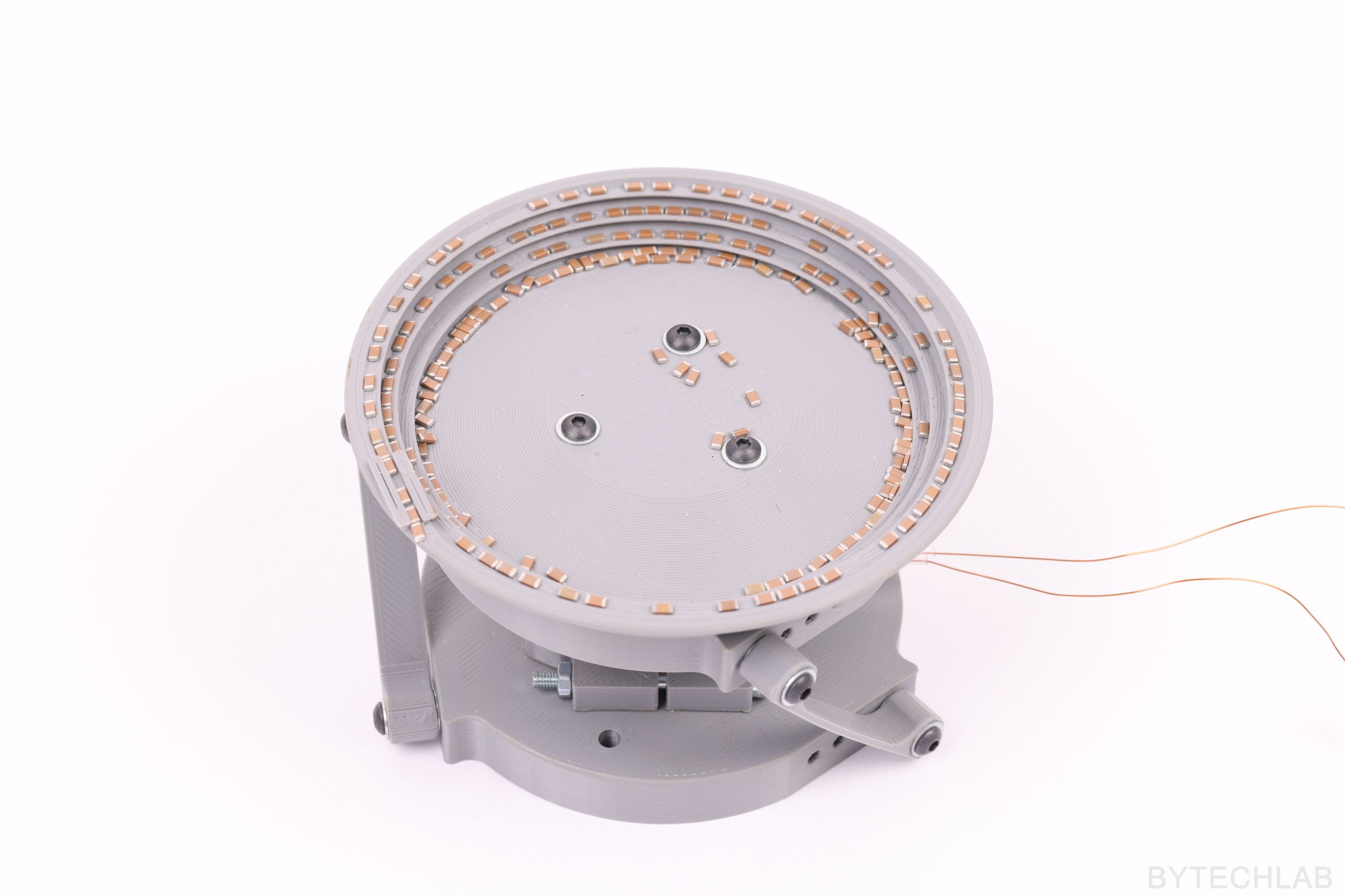
Parts for the DIY Bowl Feeder were printed with use of ABS filament due to its durability and heat resistance. Almost all parts were printed using a 0.2 mm layer height. However, the bowl required a layer height of 0.1 mm to ensure that inside surface of the helix is as smooth as possibile. If layer height isn’t low enough, layers form a “stairs” on the upper surface of the helix that block moving parts. The problem is that even with 0.1mm layer height layers form small stairs on the helix.
So what’s the solution? The bowl needs be sanded and smoothed with acetone vapor to get rid of any unevenness that might cause parts to get stuck.
In the screenshot below, you can see the problem of stairs formed on a helix surface:
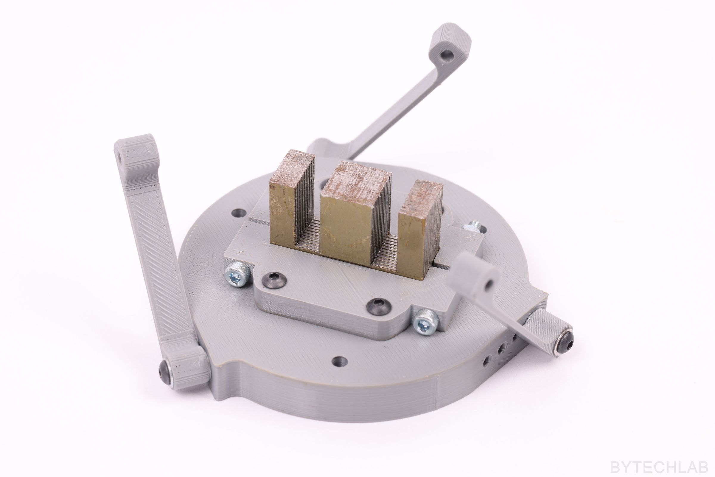
ELECTROMAGNET & COIL WINDING
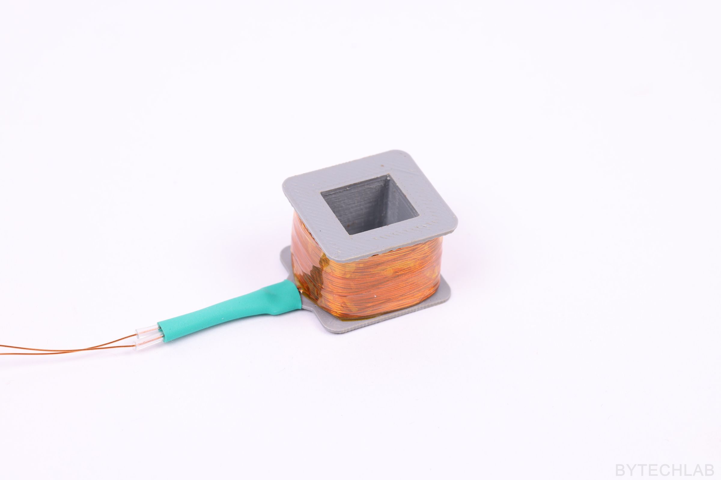
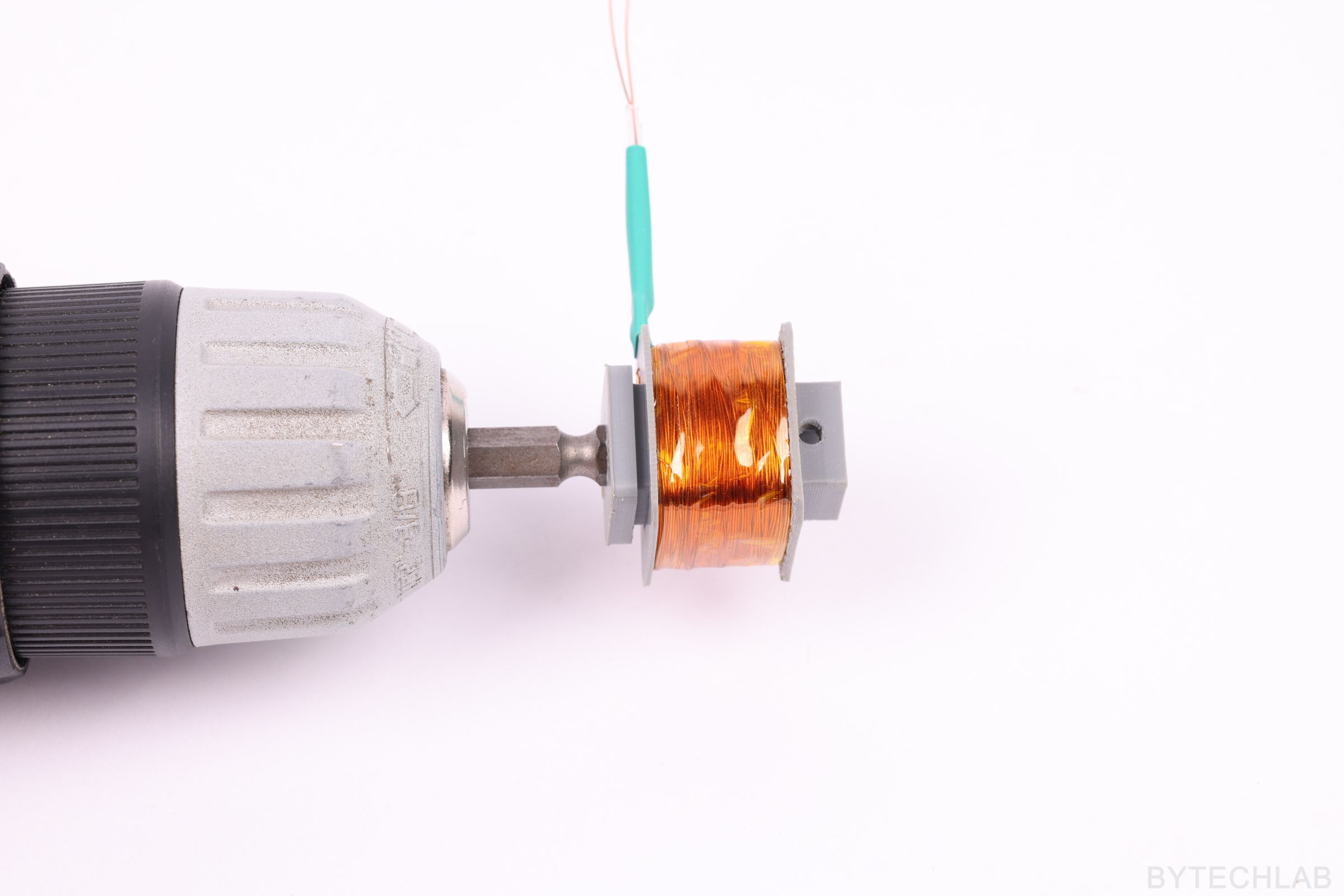
I started winding the electromagnet coil by designing an adapter that allows the “3D printed separator” to be attached to the drill. The separator contains special holes that prevent the copper wire from unwinding and breaking off. The coil was wound with a 0.3 mm diameter copper wire coated with insulation enamel. You must be wondering why I’ve used this diameter. I’ve made some calculations that allowed me to determine the intensity of the magnetic field at constant voltage and a fixed space inside the E-shaped transformer core. As you know, there’s a catch. The thicker the wire the less coils fits to the inside of transformer core, but we can push more current through it before it gets seriously hot.
As always, it was necessary to compromise between two important factors. In this case between the intensity of the magnetic field inside the inductor and the current drawn by the coil at the set voltage.
After winding the coil, it was secured with a kapton tape and several heat shrink sleeves. I don’t know the exact number of coil windings because in this case it is not that important (the only thing that matters is the intensity of the magnetic field caused by the current flow in the coil).
HOW DOES IT WORK?
A powerful electromagnet attracts a steel plate attached to the bowl, It causes the bowl to move quickly down. At the same time, during the lowering of the bowl, a small torsional movement along the main axis is made (thanks to the springs which are set at an angle). SMD parts can move up along the helix due to vibrations in 2 directions happening at the same time. The whole thing works only at a strictly defined resonant frequency.
The SMD parts, due to their inertia, float for a while in the air while the bowl quickly falls down and twists a little. At some point, the parts fall on a lowered and twisted bowl. Then the bowl begins to rise with the SMD parts placed on a helix in a new position, this cycle repeats about 76 times per second (resonant frequency of this particular setup). The resonant frequency depends on several factors: type of springs, mass of the vibrating assembly,shape of the helix, shape and mass of the SMD parts themselves.
TESTS
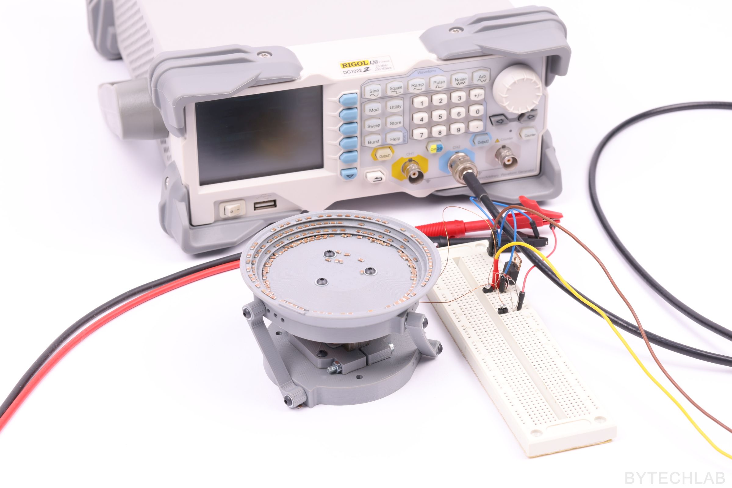
DIY Bowl Feeder tests were carried out to check whether the whole device works as it should. During the first tests there were some problems with the proper adjustment of the bowl springs (the SMD parts didn’t wanted to move up the helix or they were instantly falling down from it). After adjusting the springs and the distance between the electromagnet and the bowl itself, the device started to work properly.
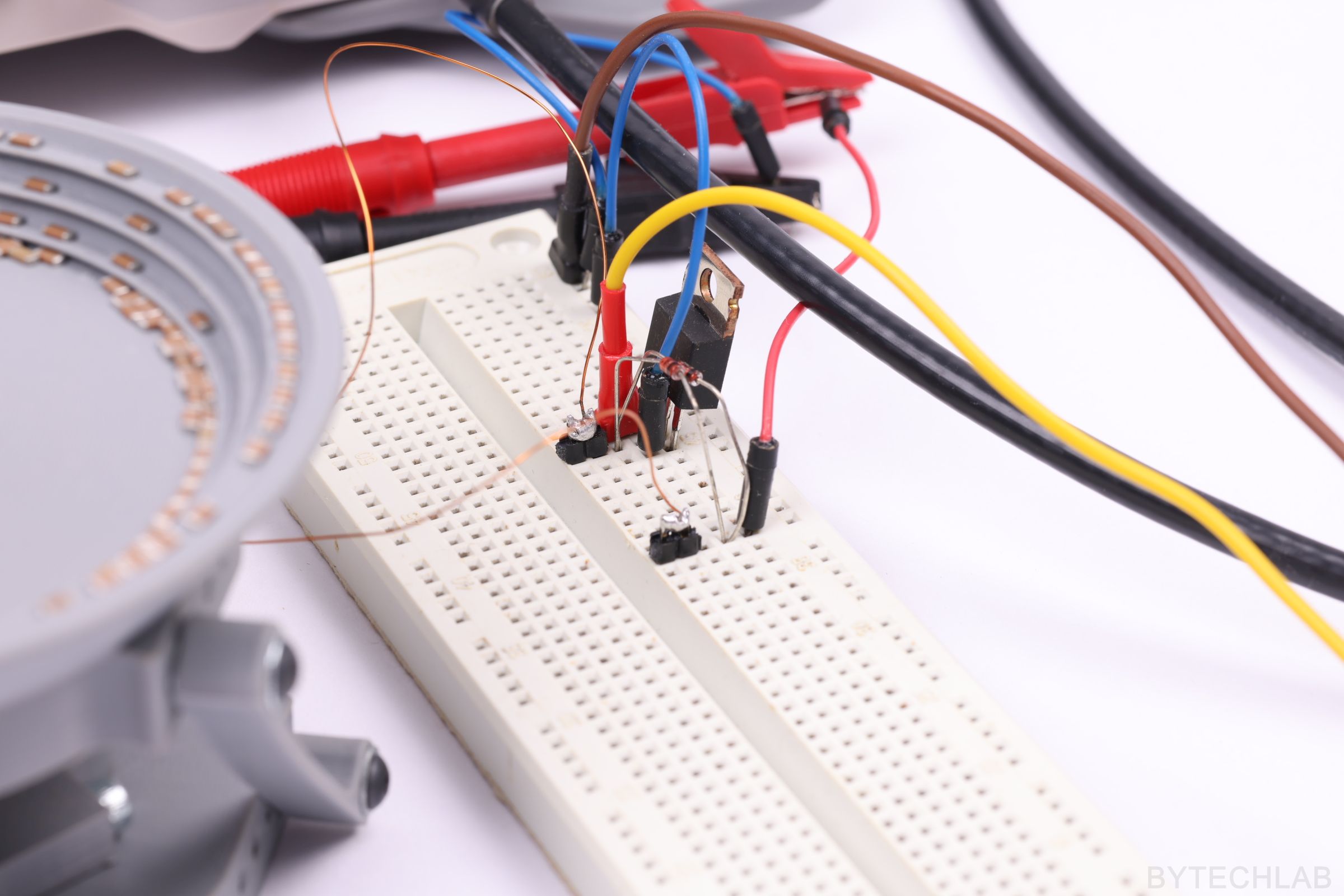
The only thing left to do was to find appropriate vibration frequency using the signal generator, in this particular case it was about 76 Hz (resonant frequency). I used an ordinary MOSFET-N transistor to switch the coil on and off (of course I’ve used some fast “flyback diodes” to prevent high voltage spikes from appearing and killing the transistor). Below you can see how the whole thing works after some adjustments:
TESTS – VIDEO
LINKS TO .STEP & .STL FILES
- Grabcad [CAD]: https://grabcad.com/library/smd-parts-bowl-feeder-prototype-1
- Thingiverse [STL]: https://www.thingiverse.com/thing:3017796
SUMMARY
The DIY Bowl Feeder requires a few more modifications and improvements, but everything works as it should. It’s a very clever design that is being used very often in many factories where they need to feed parts in a particular orientation to a some sort of machine. You can use this bowl feeder to feed all sort of stuff: bolts, washers, bearing balls, SMD parts and much more.
UPDATE: You can read about this project also on: