
I am very happy to announce you a new very big project. 😉
If someone doesn’t already know , [IP] abbreviation in the title stands for “In progress”.
I know it may sound silly and crazy but, I’ve always wanted to make a Mars rover by myself (or at least something that will look and work like real Mars rover). I was dreaming about this project for a really long time. Finally I can make it because I have just enough equipment and knowledge.
Unfortunately the whole project is quite “abandoned” now because I don’t have enough finances to buy new parts and materials.<poor student 😐 > . Sadly I can’t show you much at the moment because the whole rover is still in design process ,many things will change and as you might already know I don’t like to show projects like this one in a unfinished form.
The only thing I can show you is overall external appearance of some parts and assemblies. I’m publishing this short article just to arouse your curiosity about this fancy rover 🙂 . Down below you can find a work log which will be updated every time a progress is being done ↓ ↓ ↓ ↓
I finally discovered that I need to redesign most of the main frame and drive gearboxes to solve some important problems which I encountered during research & design process.
For now, I will keep the whole project “secret” 🙂 .Take your imagination to the next level and try to imagine how the whole rover will look like when the whole project will be done !
As promised before I’m showing you a few renders of some parts:
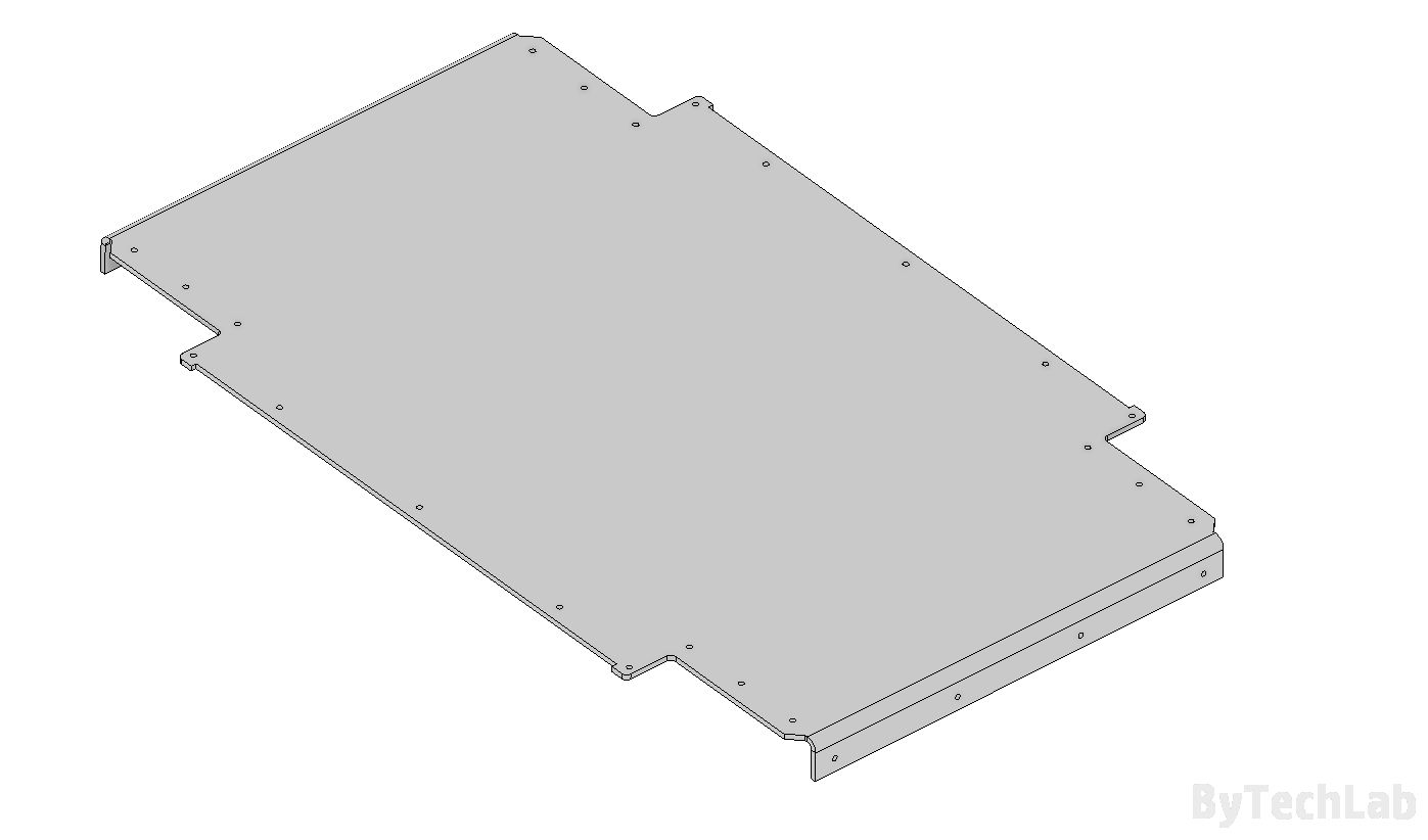
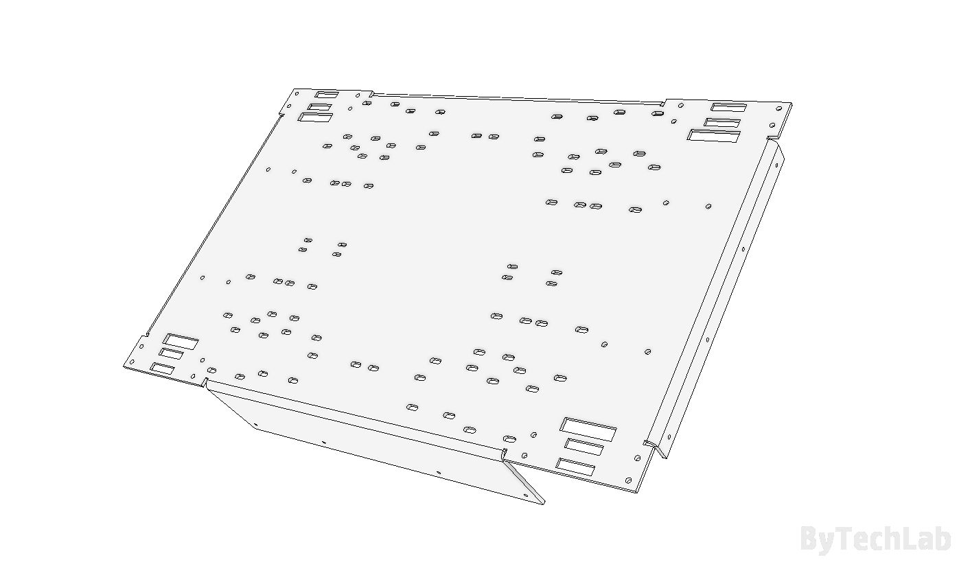
–> Top plate:
It is not finished yet on this render, many holes are missing. This top plate design will go straight to the trash, because the main frame needs to be redesigned anyway.
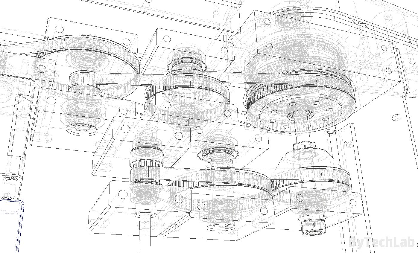
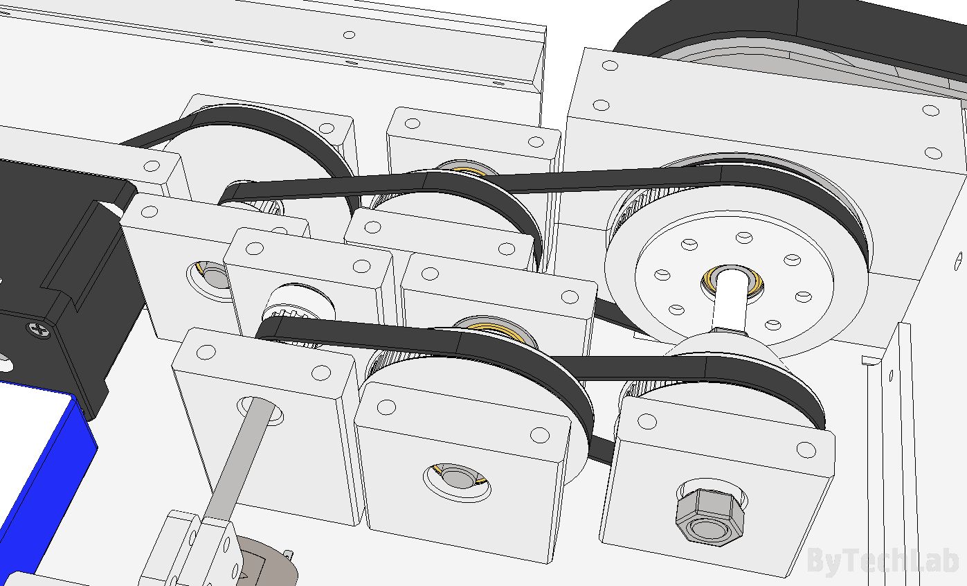
–> Main gearbox:
Main gearbox will be redesigned too, for now it is too big and too heavy. I’m designing new one in the way it will weight at least 2 times less than this one. I’ve also changed some gear ratios to improve the holding torque available at the output.
–> Bottom plate:
You guessed it! , just like the “Top plate” it will be mostly redesigned to improve overall stiffness of the frame and reduce its weight.
As it turned out later, bottom plate has some difficult 90 deg. bends which are hard to manufacture (you know, it costs much). I need to find another way around this.
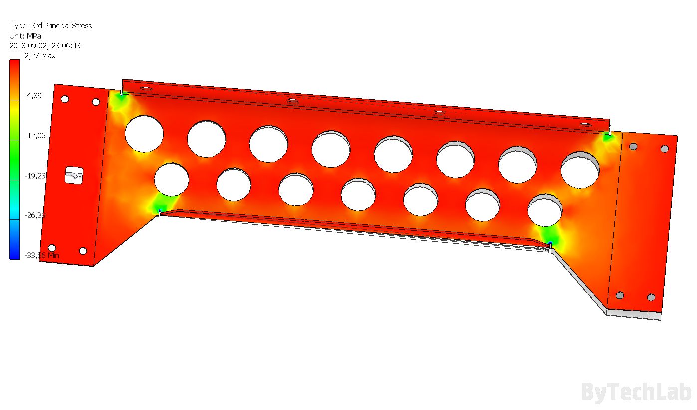
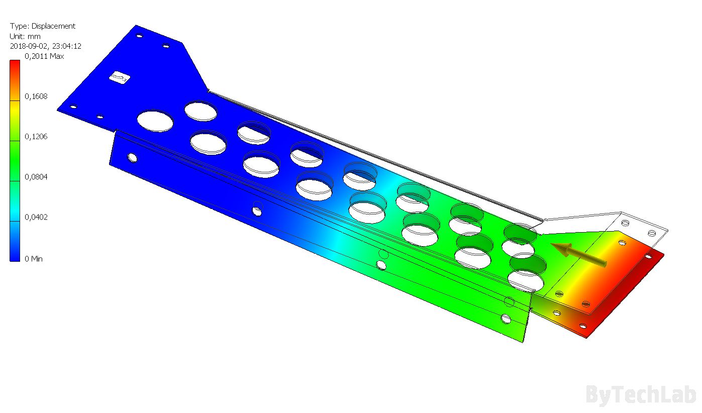
–> Top beam stress & displacement simulation:
Im trying out a few designs now , below you can see just another main frame part that will go straight to the trash 😀 because it can’t withstand the loads that it should carry (see stress points down below):
–> Arm pin assembly:
And with the trash full of failed designs we can take a look at a fancy part that will be responsible for transmitting the torque from the double and multi stage gearbox to the main drive arms.

Work log:
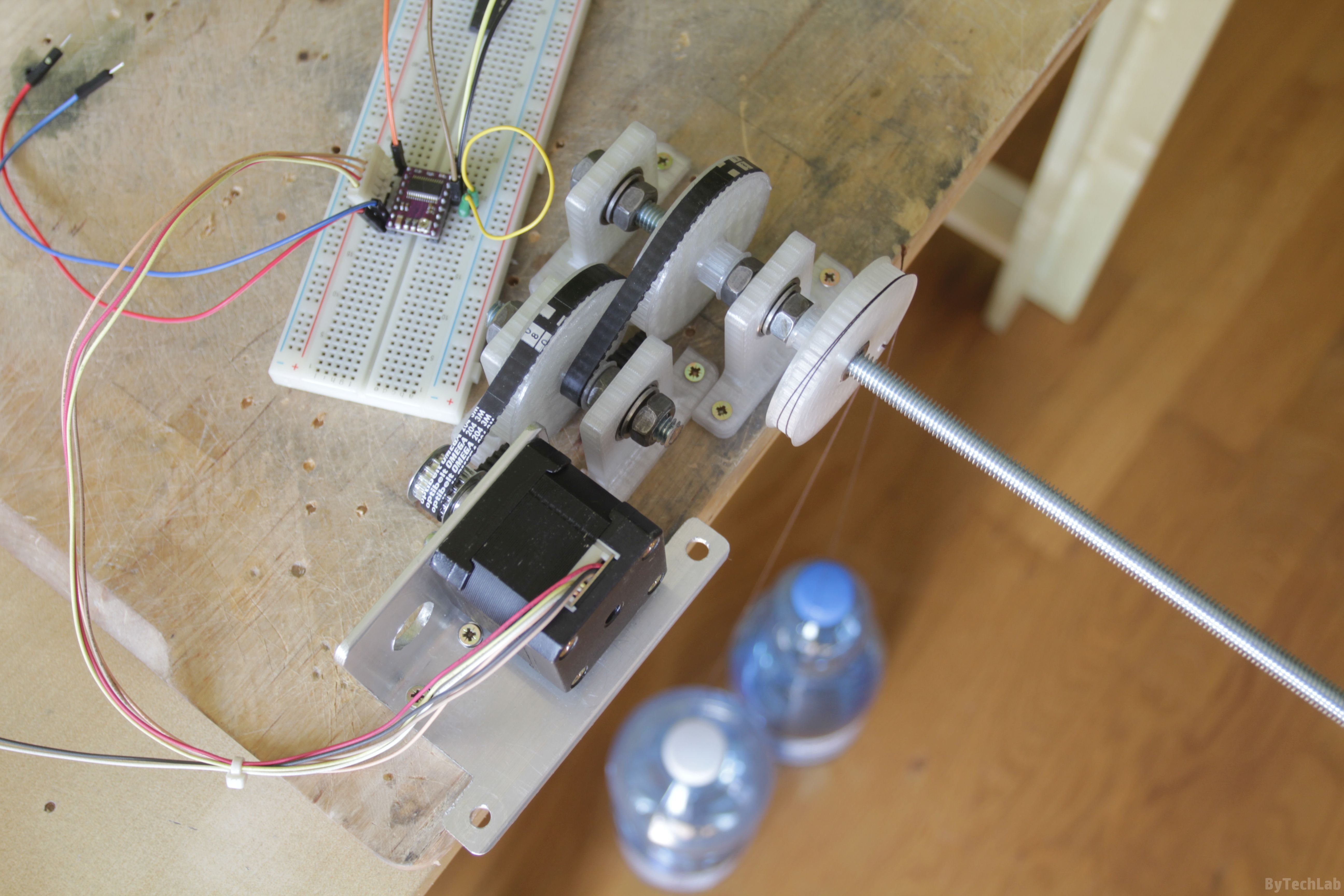
- EDIT: 10.09.2018:
I printed old gearbox just to test the whole thing out and check if there are other issues that need to be fixed before designing a new one. The whole gearbox is based on HTD3M timing belts, they are thick enough to withstand the loads that they should carry. I’ve used a stepper motor with unknown parameters so I don’t really know what’s the holding torque of it. Im sure it’s not high because it’s a quite small motor which I’ve found in some scrap.
Anyway ,if I remember correctly there should be about 15 Nm of the torque available at the output of this gearbox. This torque can be obtained only with use of a longer NEMA 17 motor (it has about 0,5 Nm of holding torque). This gearbox has gear ratio of 30:1 , so the torque from the stepper motor is roughly multiplied by 30 (i know there are some losses in the gearbox itself) and the angular speed is divided by 30. Because of that I need to balance between the torque and angular speed at the output of this gearbox.
As you might already know stepper motors lose their holding torque with increasing speed , so too high gear ratios are not suitable because it would take ages to make one full 360 degree turn at a reasonable stepper motor speed. I’m still thinking about using some beefy BLCD,s with a feedback loop.
Everything was printed from PET-G filament, It’s just fine for these pulley’s, but later I will eventually print everything from ABS filament anyway. I’ve mounted the whole thing to the table with some wood screws. During the tests I found out the belt has a tendency to skip a few tooth’s when it slips on smaller pulleys. It definitely needs to be fixed somehow.


To be continued ………. 😉
Stay tuned !
As always, you can post comments down below↓↓ (If you have any questions feel free to ask):
Don’t forget to like, follow and subscribe ByTechLab on other websites: