
I’ve got inspired by the Adam Savage “One day builds” series which is being published on Tested (YouTube channel). Because of that , I will start publishing short posts describing my “one day projects” from now. Each one of them will be tagged with [#One day projects] tag.
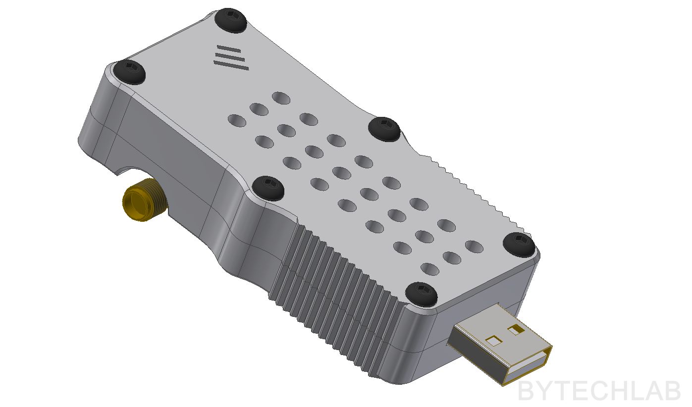
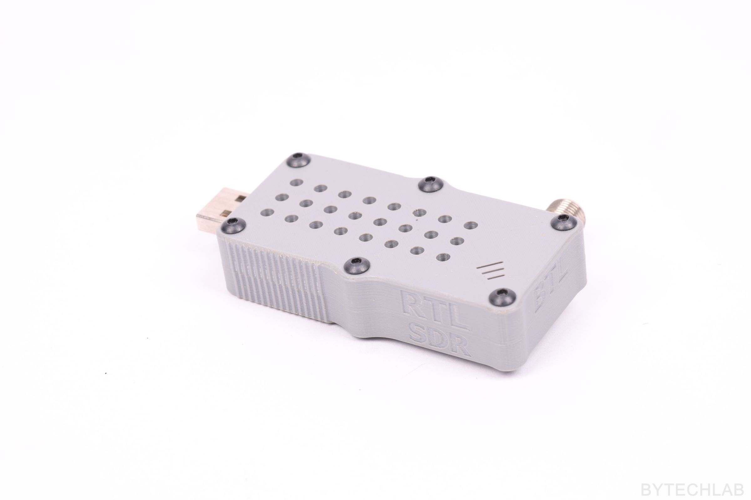
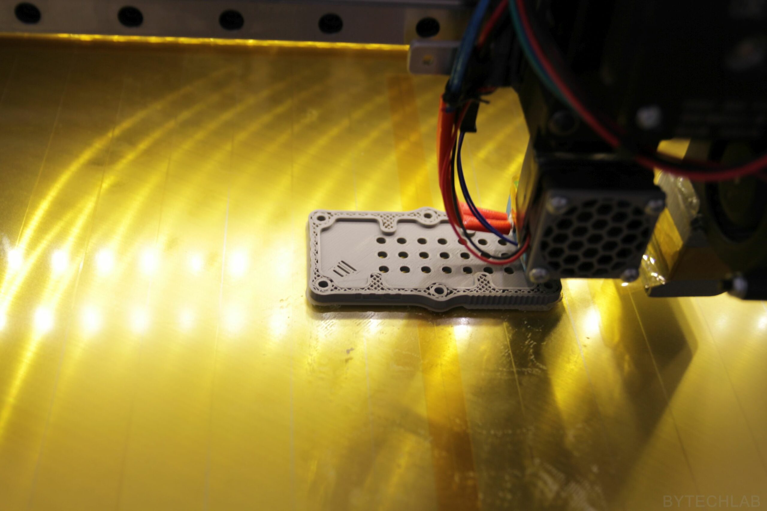
But that’s not all ,I will try to add something more to each of these posts. Hopefully you will like this idea. Today we are going to look at a decent RTL-SDR dongle case / enclosure which I’ve designed and printed in about 3-4 hours.
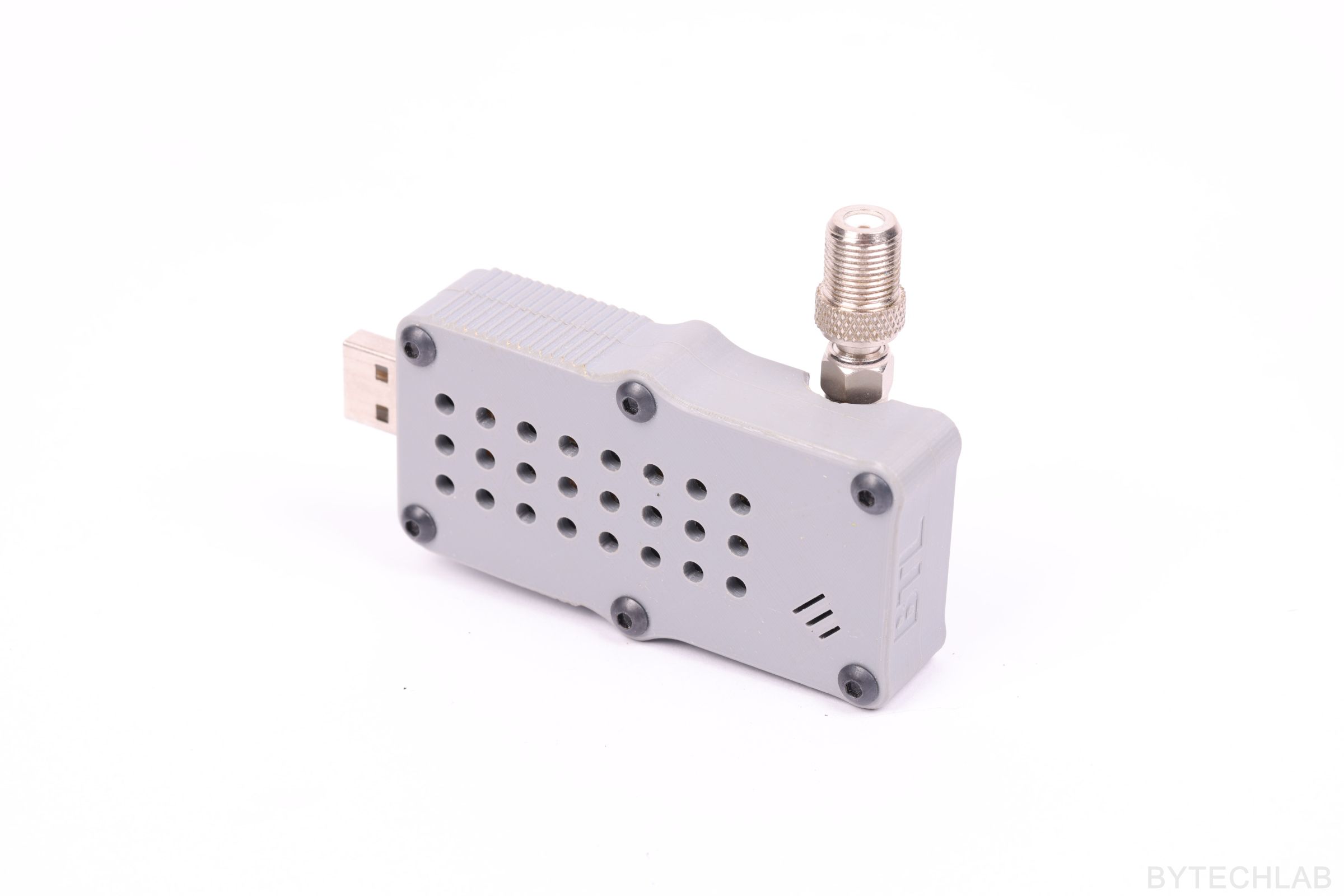
NOTE: This case/enclosure fits only to the blue R820T2 based dongle with a SMA connector soldered at the bottom side of the PCB.
DESIGN PROCESS
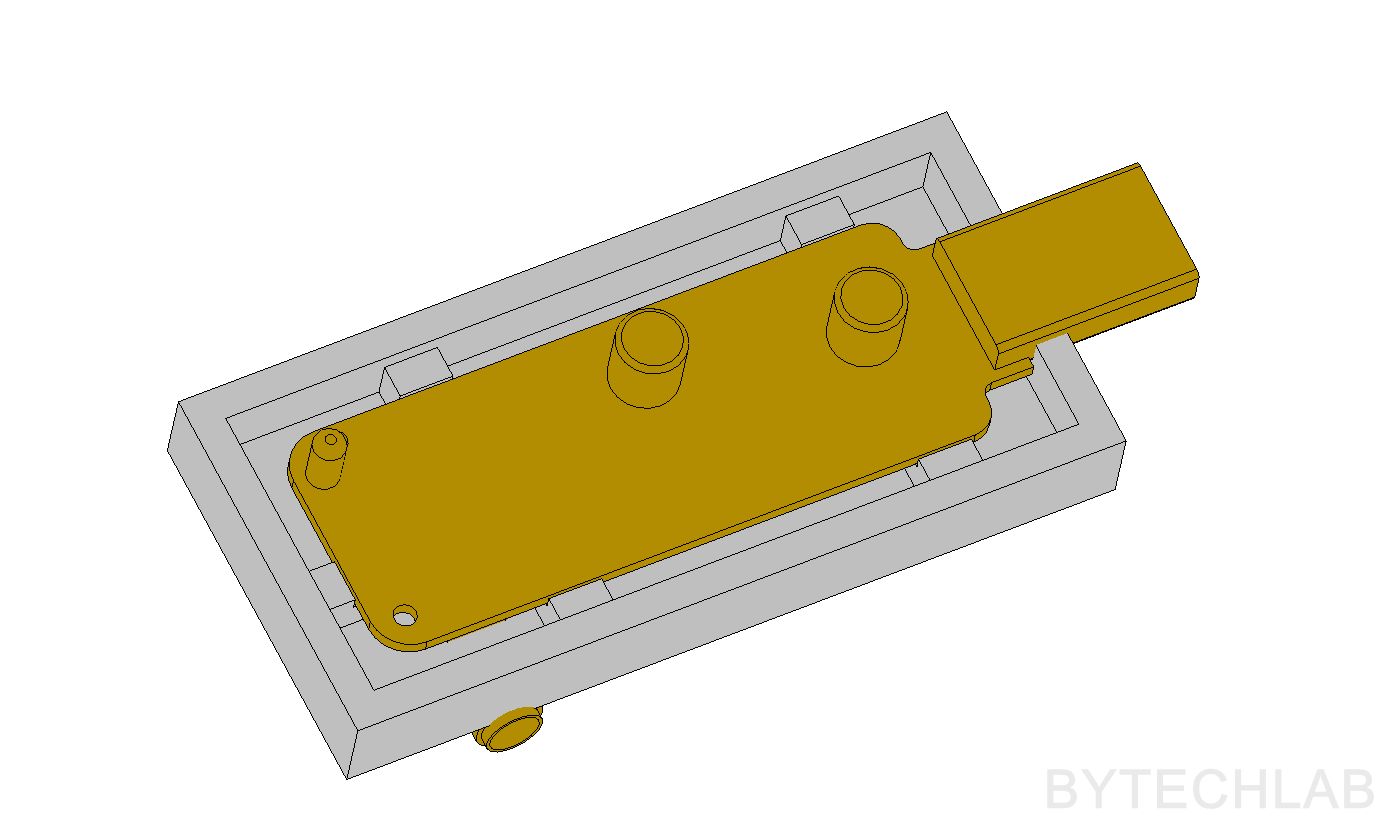
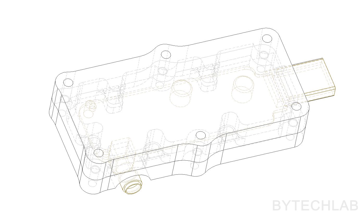
I started with drawing a rough model of the modified dongle PCB. I’ve modeled all big components on the PCB that might interfere with the case. So that I can measure everything in the CAD software and adapt the case to the dongle very easily.
A brief description of the design process:
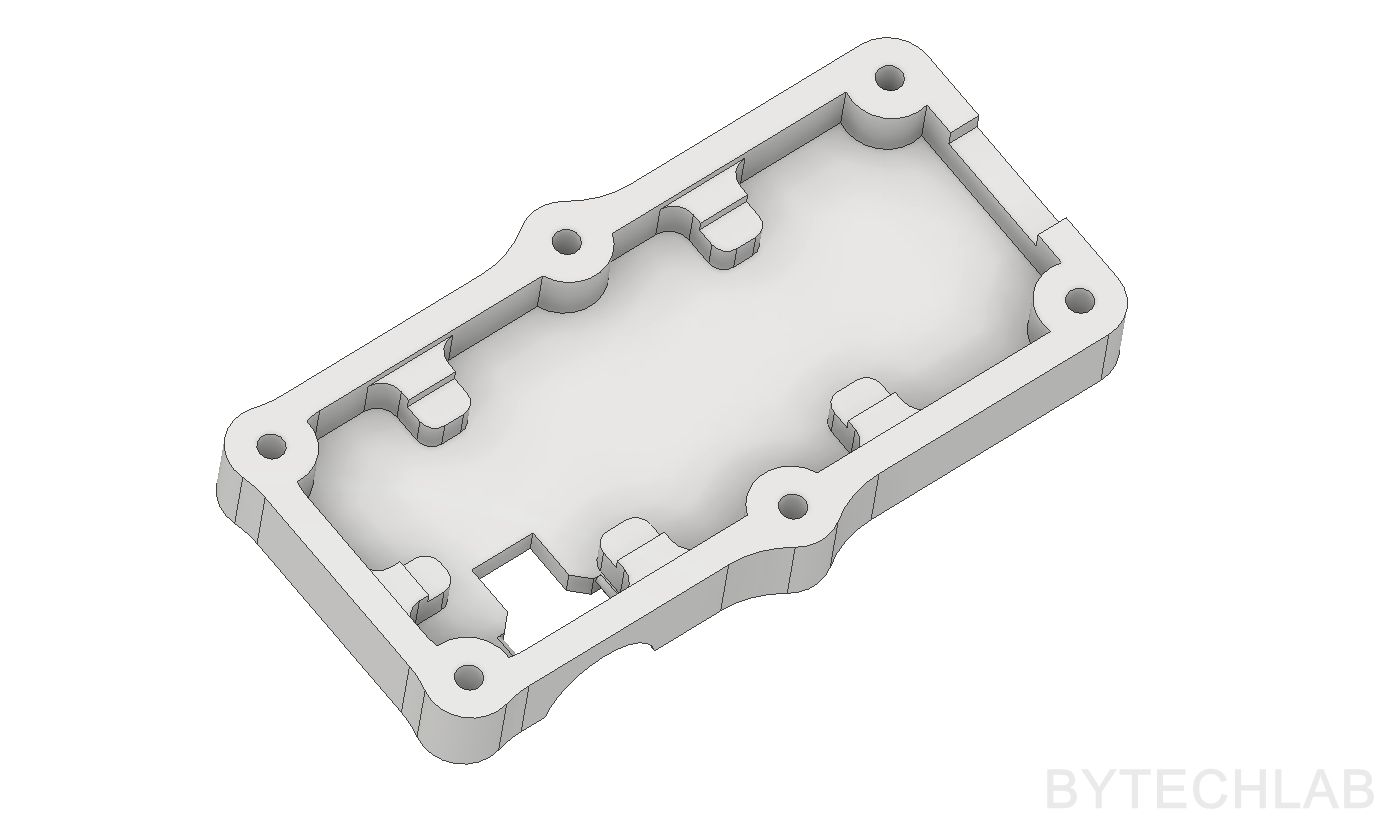
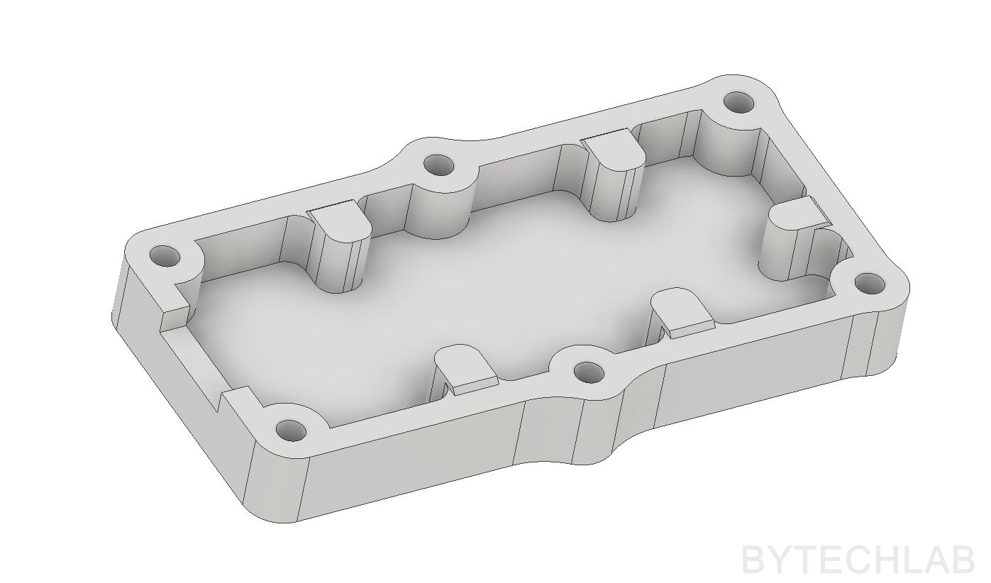
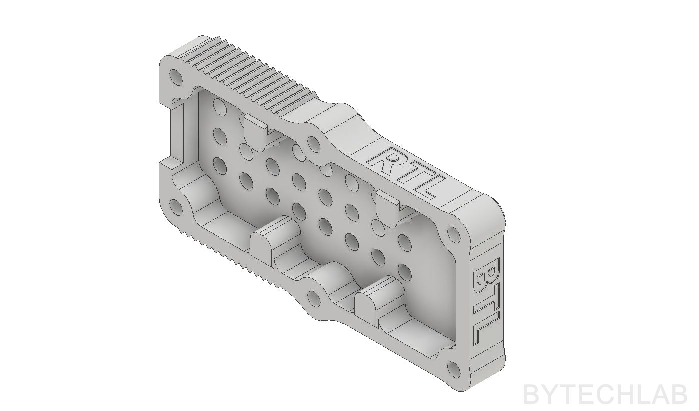
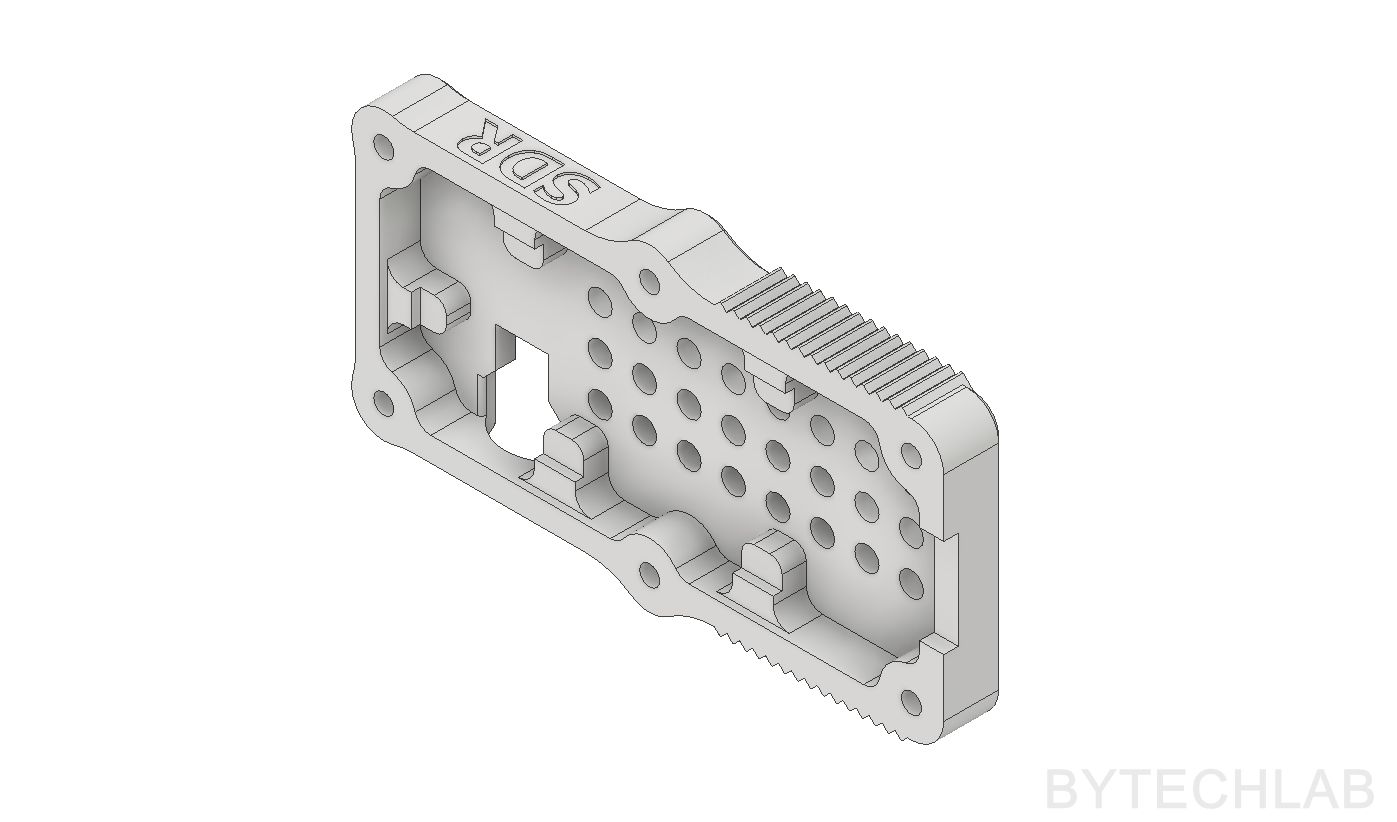
- Firstly , I’ve designed some tabs around the PCB that will hold it firmly after putting everything together. Of course every of these tabs sits in the place where the PCB has no soldered components. It is very important to take into account the layer height (there shouldn’t be any free space left between the PCB and the case tabs).
- Then I’ve roughly outlined the shape of the case around the PCB which I modeled before,
- In the next step, I’ve created a assembly with these unfinished case halves to check how everything fits together,
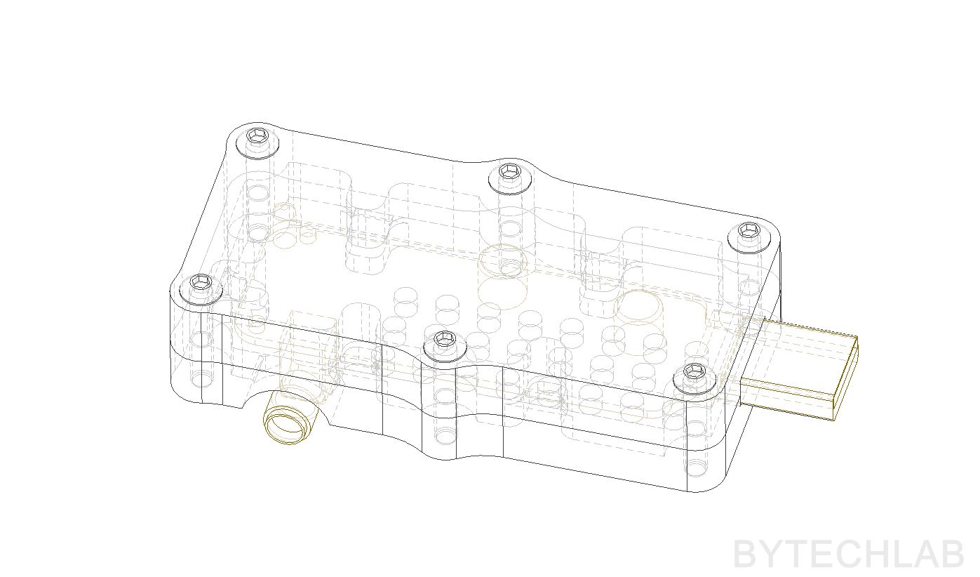
- After checking for some dimensions and clearances, I added some holes for screws,
- At this stage I’ve added some chamfers and fillets to improve overall external appearance and get rid of sharp edges that doesn’t print too well in FDM technology,
- Later I’ve shrunk the whole case around the PCB to reduce it’s size as much as I could,
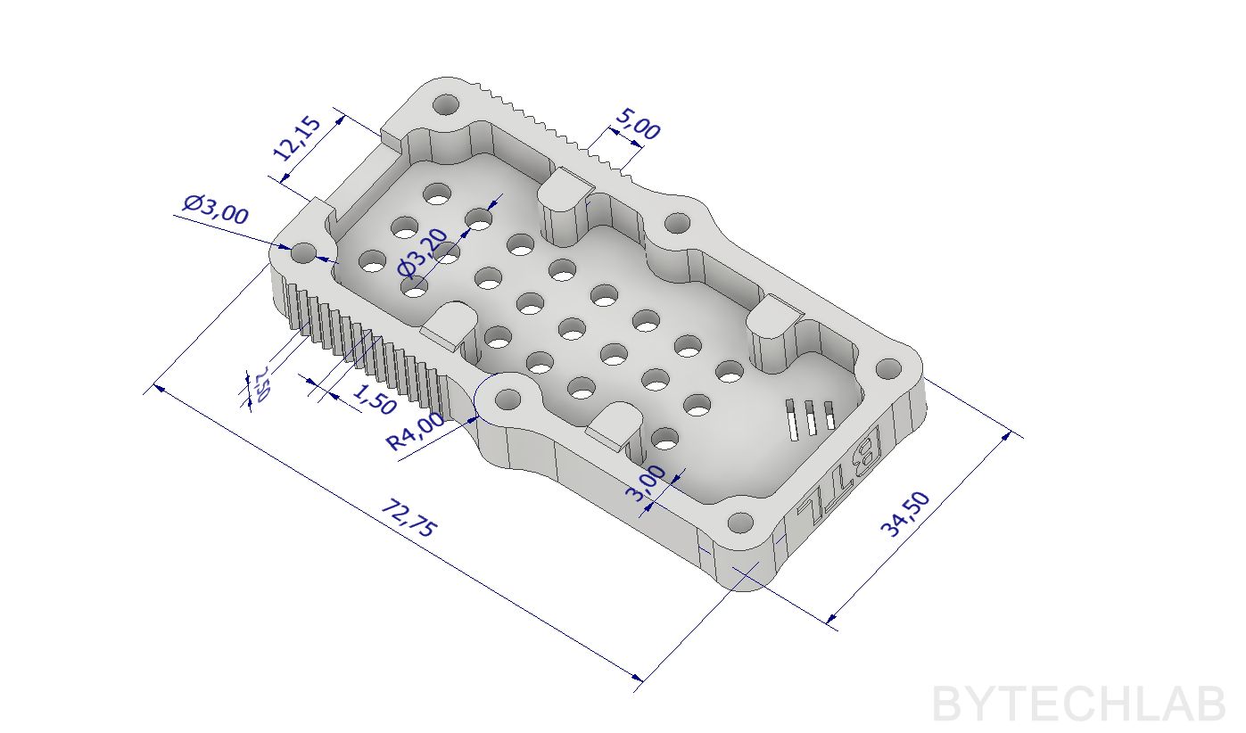
- In the last step I’ve added: some text on the sides , vent holes to improve the air flow and a rectangular hole for the SMA connector of course.
And that’s it!, really nothing fancy 😉
In order to make a simple shielding of the RTL-SDR dongle case, you can cover the case halves with thin copper foil from the inside and then connect them to the GND in the USB connector.
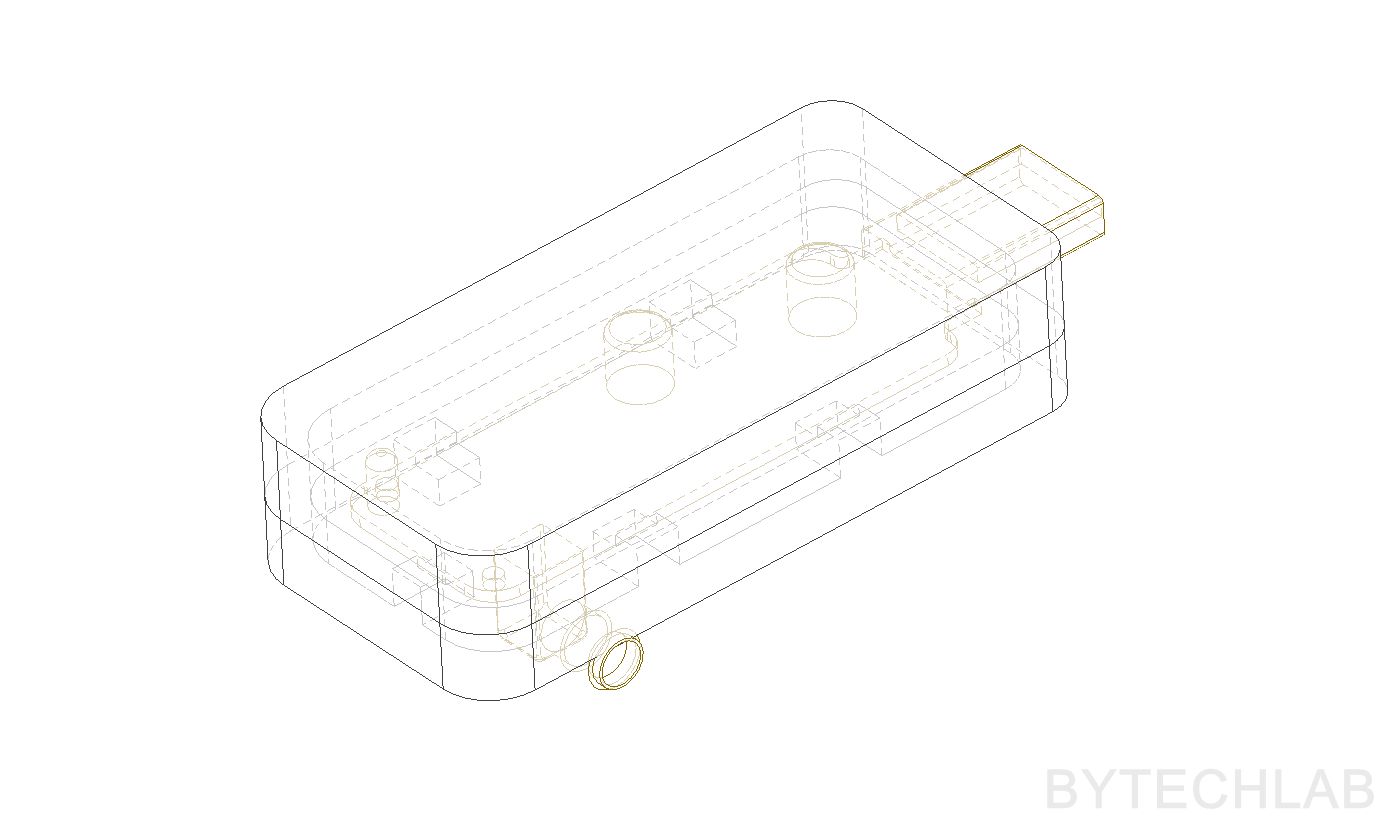
Below you can see a render from each step of the design process:

SOME DESIGN TIPS FOR FDM TECHNOLOGY (WITHOUT SOLUBLE SUPPORTS)
Probably most of these tips are quite obvious for more experienced people, anyway someone might find it interesting , so let’s start!
- Avoid extreme overhangs,
- Always try to design the whole thing in the way that it can be printed without any support material,
- If you need to add some holes for bolts/screws always make them bigger if you don’t want to drill them to make them fit (for ex. add about 0.15 mm or even 0.2 mm to every 3 mm dia. hole),
- Avoid thin vertical walls , It really depends on your printer setup but you shouldn’t go for single or double extrusion walls. Usually these walls doesn’t look good, they are not durable either.,
- I found that the thickness of 3 mm of every vertical wall works the best along with the 0.4 nozzle and a 0.45 mm extrusion width (We need to have some free space for the infill, in my case I have about 1.2 mm of free space for the infll [4 x 0.45mm perimeters = 1.8 mm ]) If you don’t have some space for standard infill ,some problems with the pressure in the nozzle might appear (especially if you are slightly over-extruding),
- Avoid vertical dimensions that can’t be exactly divided by the layer height,
- Avoid very sharp edges, they don’t print well in this technology , always apply some fillets and chamfers. The print will look nice and the risk of appearing any ringing or ghosting is greatly reduced,
- Always add clearance in places that must fit other objects (For ex. I’ve enlarged the USB connector slot by 0.15 mm in the vertical plane),
- I’ve found that text extruded 0.25 mm to the inside of the print (concave to the inside) works the best.
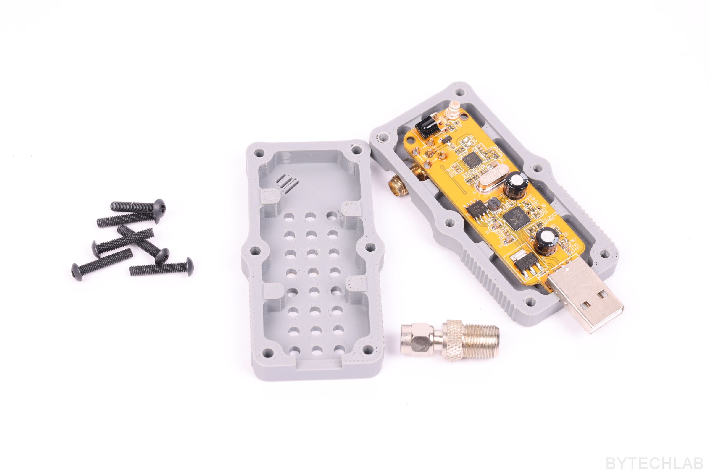
MORE PHOTOS

RECOMMENDED PRINTING SETTINGS
- Layer height: 0.1 mm
- Heated bed: 90 deg C or more
- Printing speed: 40-60 mm/s
- Filament: ABS/ASA
- Infill: 25% (Grid) or more
- Outlines: 2 or more
- Top/Bottom 100% layers: 4 or more
- Support: No
- Nozzle diameter: 0.4 mm
- Extrusion width : 0.4 mm
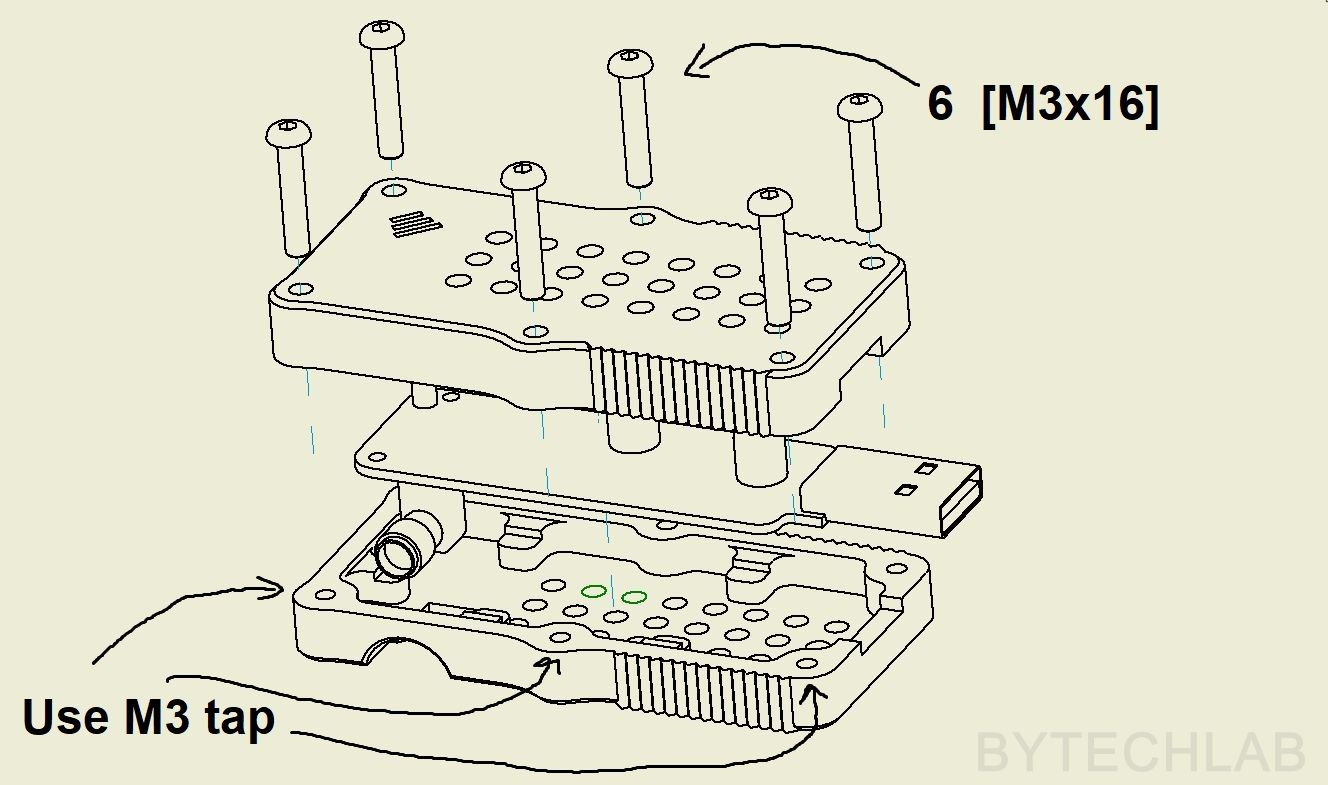
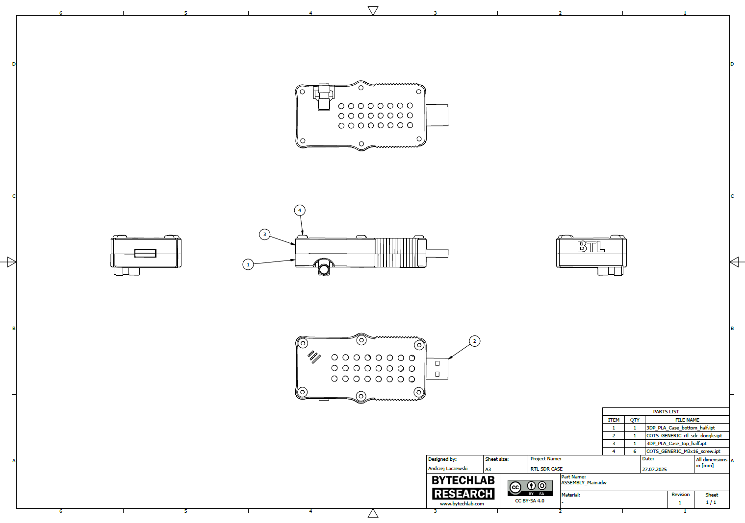
ASSEMBLY INSTRUCTIONS
LINKS TO STL & CAD FILES
- Grabcad [CAD]: https://grabcad.com/library/rtl-sdr-dongle-case-1
- Thingiverse [STL]: https://www.thingiverse.com/thing:3093321
UPDATE: You can read about this project also on: