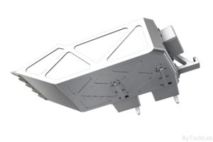
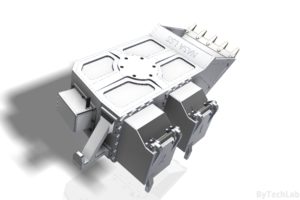
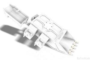
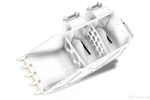
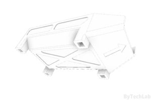
Overall description of the competition:
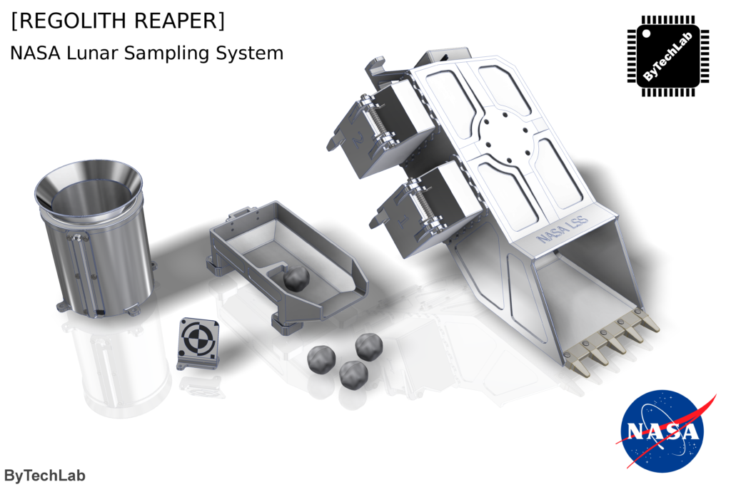
NASA is seeking to challenge the GrabCAD Community by sponsoring an open competition in which participants design a sampling system to collect lunar surface materials for return to Earth and subsequent scientific analysis. The competition will be to design a sampling system that is capable of acquiring a defined amount of regolith (rocks and dust) within specific size ranges while operating under the provided constraints. The winning designs will be built and tested by NASA and used to inform potential future sample return missions on possible sampling methods.
Sample return missions are constrained by mass, power, and operating time. There is a need for a lightweight, low power sampling system that is capable of sorting the collected regolith so only specific types of materials are returned. Rocks in the ~1 cm size range are well suited for scientific analysis. Prioritizing the collection of these materials within the design constraints is the main goal of the competition.
Source: https://grabcad.com/challenges/nasa-lunar-sampling-system-design-challenge
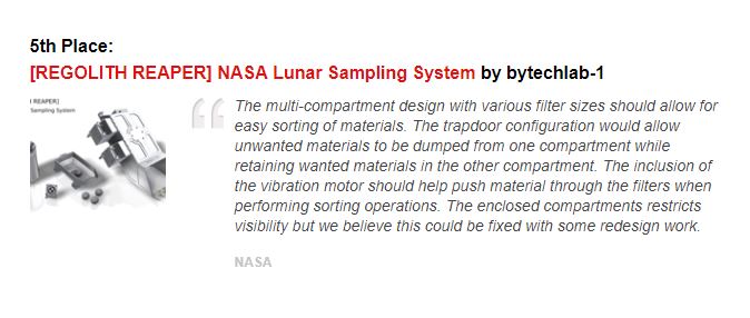
UPDATE: I won the fifth prize!
Source: https://grabcad.com/challenges/nasa-lunar-sampling-system-design-challenge/results
Principle of operation (sorting process):
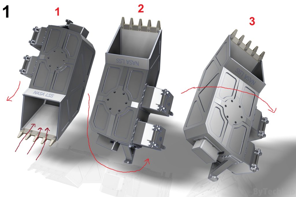
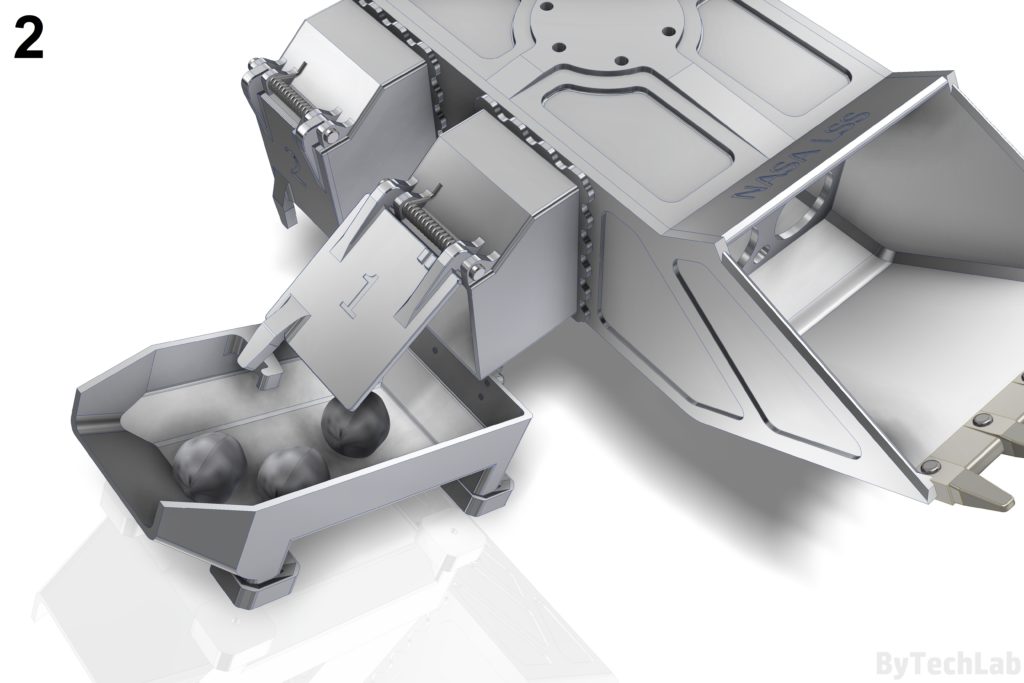
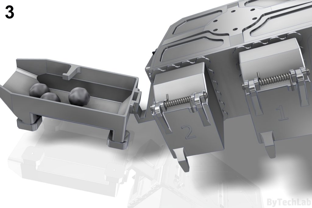
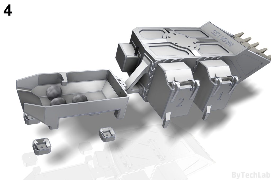
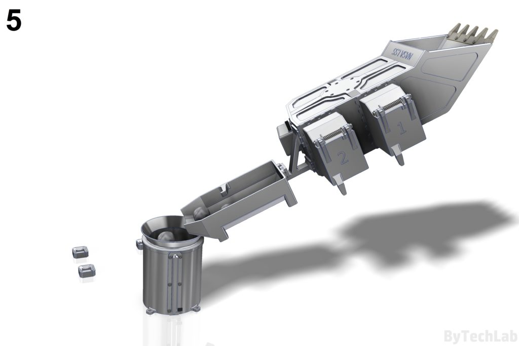
Numbers in [] brackets correspond to the render number.
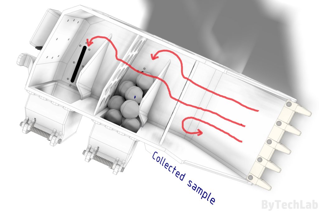
The whole process of sorting the regolith proceeds in the following steps:
– Digging up the regolith until a layer of interest is revealed
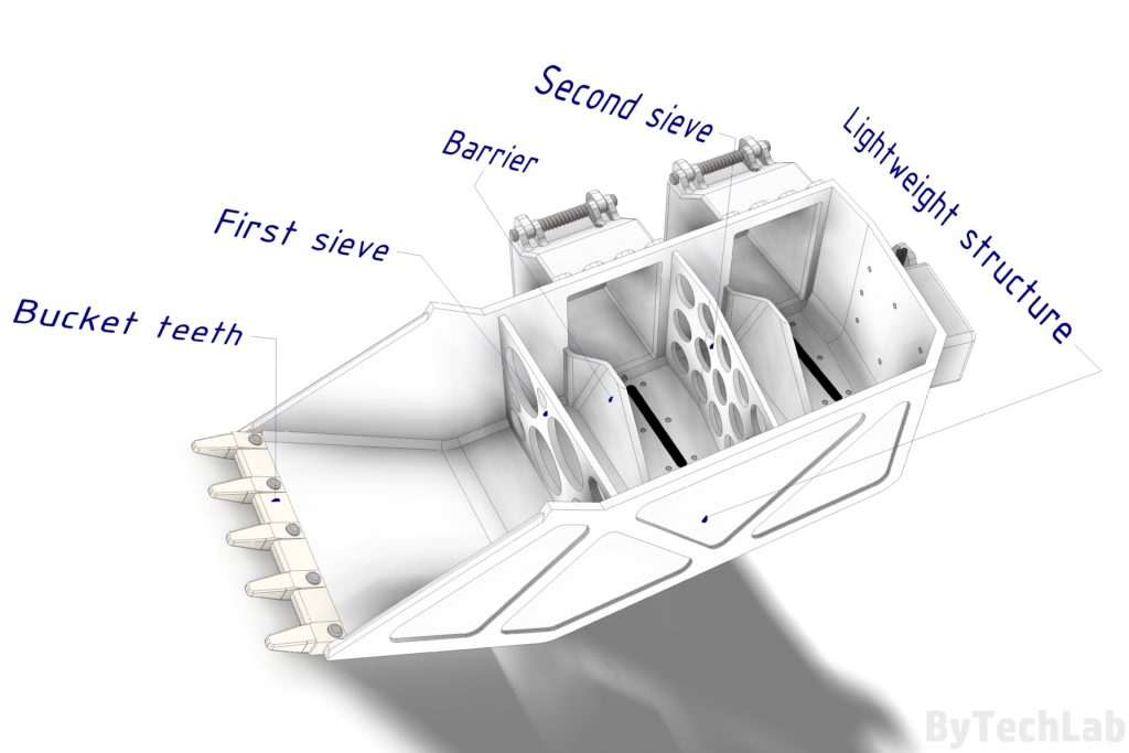
–[1][1] Firstly ,a sample of regolith is being taken in to the “digging bucket”,
–[1][2] Then the whole thing must be flipped 180 deg. relative to the ground (upside down),
–[1][2] Vibration motor turns on,
–[1][2] Then we need to wait for the sorting process to be accomplished,
–[1][3] In the next step , the bucket needs to be turned by 45 deg or more to the side of it (regolith must fall into the outlet channels),
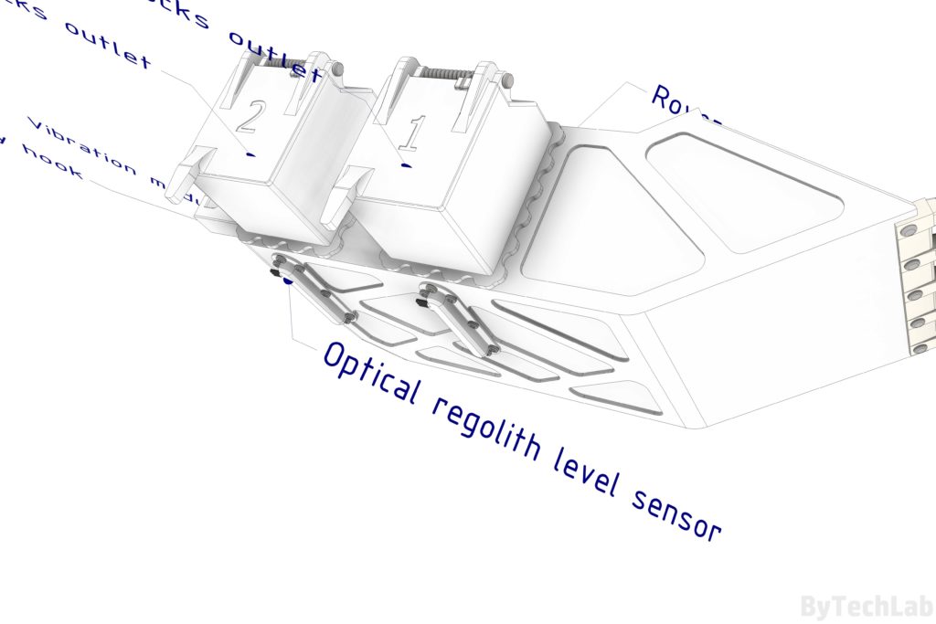
–[1] The whole process should be repeated until two outlet channels are full of sorted material (optical regolith level sensors will indicate that)
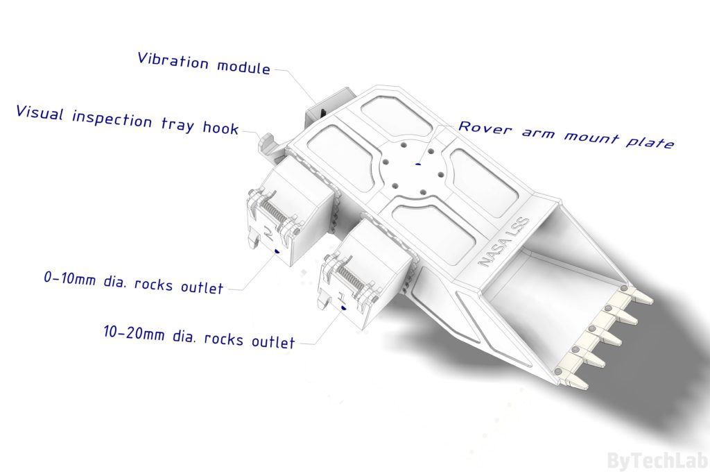
–[2] After filling both outlet channels , selected type of sorted regolith (0-1 cm or 1-2 cm) ,
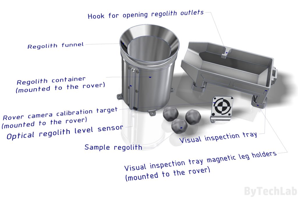
is ejected to the visual inspection tray with use of a hook embedded in the visual inspection tray.
The doors on the regolith outlet channels are spring loaded , so that they don’t open during “normal” digging operation.
–[3/4] After performing a visual inspection , the sample can be rejected
from the whole system by simply lifting the whole tray from the rover and spilling the sample on the surface of the planet.
In case the sample meets requirements , the tray is being lifted up by the rover arm and moved above the regolith container.
–[5] The whole tray with the regolith is tilted towards the regolith container, in the way the sample doesn’t fall to it yet.
Then the vibration motor turns on and regolith starts to slowly fall in to the container.
Optical regolith level sensor reports the overall regolith level. When the amount of regolith needed falls into the container, the vibration motor turns off.
The leftovers can be thrown away just like in the first point [1].
The whole process described above is repeated with other type of sorted regolith to form another layer that meets the requirements.
For ex. Firstly we can drop [1-2 cm dia.] regolith that forms a 2 cm high layer on the bottom of the container. Then we can drop [0-1 cm dia.] regolith at the top of previous layer to form another layer that is 1 cm high (for ex.).
The whole process is repated until sensor reports that container is full.
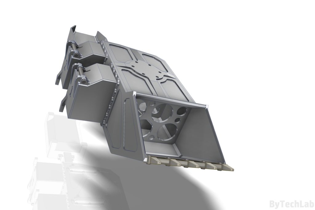
Annotated renders:
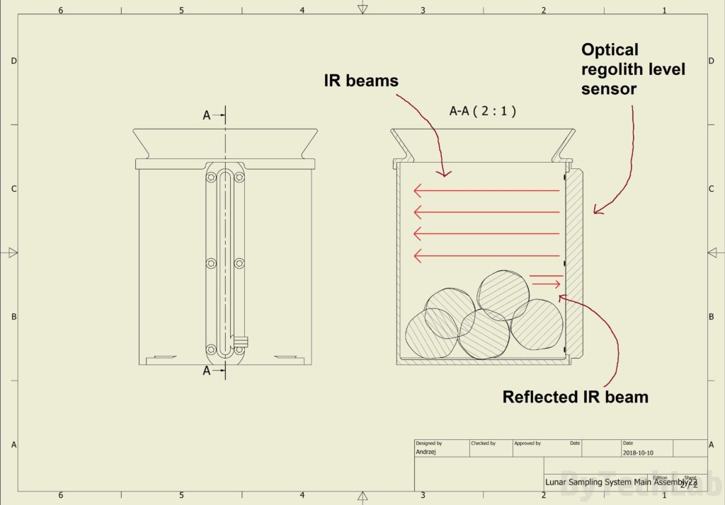
Regolith container & optical regolith level sensors:
The optical regolith level sensor, senses the level of regolith by sending many parrallel IR beams towards the inside of the regolith container.
The phototransistors or other photosensitive devices detect reflected beams.
So that received IR beam is stronger in the part of the regolith level sensor where it is covered with the sample. IR beams are sent through a transparent window.
More renders:
Links:
-> NASA page: https://www.nasa.gov/feature/sample-return-regolith-sorter-design-challenge
-> My entry: https://grabcad.com/library/regolith-reaper-nasa-lunar-sampling-system-1
-> The whole contest : https://grabcad.com/challenges/nasa-lunar-sampling-system-design-challenge
Description and other stuff:
The whole digging bucket is connected to the rover arm through the arm mount plate.
Visual inspection tray magnetic leg holders, camera calibration target and regolith container are mounted on the rover/lander main frame.
Total weight:
-460g including regolith container
-416g without regolith container
Everything is machined from:
-6061 aluminium
-Steel
-Titanium (bucket tooth)
Power consumption:
– Around 5-10 W for vibration module
– Each Optical regolith level sensor draws about 1W or less
Total power consumption (worst case scenario): 15 W
It’s rather hard to tell how long the whole sampling operation would take, it really depends on many factors (for ex. how fast the rover/lander arm will move, how many different layers will be deposited into the container, etc.). There also might be need for digging deeper than usual , to find the regolith that NASA is looking for.
I can roughly estimate, that the whole operation of filling one regolith container would take from about 30 min to one hour to complete. As I said before it really depends on many factors.
The whole sampling process will be mostly automated to minimize the risk of doing something wrong. I mean that the whole sorting and regolith deposition move sequence will be pre-programmed on the lander/rover so that, anyone doesn’t have to worry about it on the earth. Only the digging process will be remote controlled directly from the earth. The rest will be a ‘one-click’ sequence ( sorting sequence, visual inspection tray sequence , accept or reject sample sequence, scoop cleaning sequence, etc. ).
Other ideas:
– I would consider adding a ‘micro’ linear actuator on the visual inspection tray hook, that would lock the whole ting in place by inserting a lock-pin to the hole located in the tray. But I don’t think that’s really necessary.
– Visual inspection tray can be replaced by a ‘chute’ that will tilt forward and backward to deposit the sample in the container or spill it around the lander/rover after the visual inspection. But that would definitely make the whole system more complex (a linear actuator is needed).
As always, you can post comments down below↓↓ (If you have any questions feel free to ask):
Don’t forget to like, follow and subscribe ByTechLab on other websites:

