

You must be wondering why I’m reverse engineering HerkuleX DRS-0602 servo. The answer is pretty straightforward: someone has damaged it by connecting the power supply to the wrong pins of the pin header. As you might have guessed it, the magic smoke has escaped immediately ! .Obviously I could just buy another one, but the main problem with that is the cost. This servo costs around 320$ + shipping. Upssss , that hurts! Because of that I’ve decided to attempt a repair of it. The next reason why I’ve decided to repair this serwo is that I’ve found that there is a XMega micro controller under the hood (it should be very easy to write a basic code to drive this servo).
UART RX and TX lines are next to the VDD and GND pins which is a bad thing – it is very easy to accidentally swap these and connect VDD to the UART TX or RX lines. That’s why you should always double or triple check what goes where before you power on your expensive device/equipment!
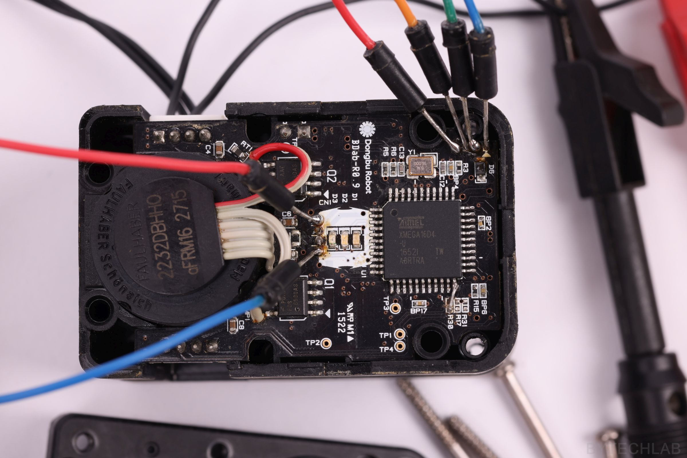
Due to this mistake the microcontroller as well as the logic level shifting circuit for the UART were burned/ damaged. I’ve started the repair by removing the old uC with hot air gun. Immediately after that I’ve soldered a new one. Of course I’ve tried to download the old firmware form the burned microcontroller, but as you might have guessed it the manufacturer has locked it with lockbits, so I couldn’t do anything with that.

REVERSE ENGINEERING THE PCB
I think that this PCB has 4 layers (I’ve noticed some connections that are not directly visible on the top or bottom layer). I finally understood that it will be a pain to reverse engineer all of the connections with components that are soldered on the PCB. There are many components that are not important from my point of view (bypass caps, pullup/pulldown resistors etc.). I just want to “hack” it and make it work. These are the main reasons why I haven’t made a full schematics of this PCB.
Instead of drawing full schematics I’ll explain where are the most important components , how they are connected to each other and what they do in this circuit.

I’ve marked most of the components with colored circles in the way its easier for me to explain everything. Of course, I’ve described pin-out of the programming header as well as the motor cable.
2 purple circles – 2 IC,s (PDAAEFDS 6990AS), I haven’t found any datasheet for them, but I suspect that each of these IC,s contains 2 MOSFET-N transistors. How do I know? Simply because you need 4 transistors for H-bridge to make it work. Beyond that, I’ve found that a half bridge driver is designed to drive only N type mosfets.
Yellow circles – H-bridge power supply filtering caps, there are 4 ceramic MLCC,s with unknown value and one 4,7 uF electrolytic capacitor connected in parallel with all of them. The main purpose of these is to filter out some of the noise generated by the running DC motor which is being continuously switched on and off by the PWM. The next reason is to smooth out the voltage of the main power rail.
Light blue – 16 MHz external crystal oscillator with load caps (I think that they have the value of 22 pF )
Blue – Voltage divider used for logic level shifting for the UART interface, it decreases the voltage levels from 5V- to 3.3V, unknown values (I would have to de solder them to make an proper measurement). I don’t know the reason why they have decided to implement a “5V UART interface” on 3.3V micro. I guess that they wanted to make it Arduino compatible.
Green – Microcontroller power supply voltage decoupling caps (probably 100nF for each VDD pin)
The rest of the resistors on this side of the PCB are used for pull-up’s and other things like that. There are also 3 LED,s with current limiting resistors, you know nothing fancy 🙂

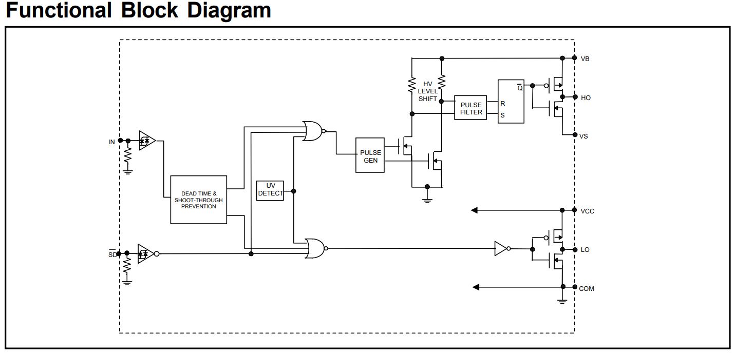
2 Blue circles – IR2104S Half bridge drivers with all necessary components around them ( you can take a look at the “Typical connections” schematic down below ).
Green – Even more ceramic decoupling capacitors used for filtering power supply lines as well as analog lines (for ex. signal from potentiometer )
Red – Starting from the left:
- There is a 5V linear voltage regulator, it is used to power up the quadrature encoder which is hidden inside motor. I don’t know why it needs higher power supply voltage than the rest of the circuit. Maybe if I had opened the motor, I would have discovered the reason for which such a voltage is needed. I haven’t done that because I don’t want to damage the motor.
- 3.3V linear regulator, it is used to power up the microcontroller and other IC,s , really nothing fancy
- A logic level converter IC, it is used to change logic levels from 3.3V to 5V (UART TX line coming from microcontroller )
MCU PINOUT

Down below I’ve described the most important connections that I’ve found after performing continuity tests with a multimeter.
The first thing that I’ve found out during reverse engineering of HerkuleX DRS-0602 servo, is that there are tons of unused pins! I don’t know the reason for which they have chosen such a big uC with so many pins. Maybe there’s something that was crucial for this strange choice. Actually, I don’t have any idea.
Naming scheme:
[Pin number],[Port],[Function]
U– Unknown function / Not connected (Most of them are not connected)
- 1, PA5, U
- 2, PA6, U
- 3, PA7, LED
- 4, PB0, LED
- 5, PB1, LED
- 6, PB2, ENCODER_A
- 7, PB3, ENCODER_B
- 8, GND
- 9, VCC
- 10, PC0, H_BRIDGE_PWM_IN_A
- 11, PC1, H_BRIDGE_PWM_IN_B
- 12, PC2, H_BRIDGE_SD
- 13, PC3, U
- 14, PC4, U
- 15, PC5, U
- 16, PC6, U
- 17, PC7, U
- 18, GND
- 19, VCC
- 20, PD0, U
- 21, PD1, U
- 22, PD2, UART_RX_VOLTAGE_DIV
- 23, PD3, UART_TX_LVL_SHIFT
- 24, PD4, U
- 25, PD5, U
- 26, PD6, U
- 27, PD7, U
- 28, PE0, U
- 29, PE1, U
- 30, GND
- 31, VCC
- 32, PE2, U
- 33, PE3, U
- 34, PDI_PROG
- 35, RESET_PROG
- 36, PR0,OSC_16MHz
- 37, PR1,OSC_16MHz
- 38, GND
- 39, AVCC
- 40, PA0, U
- 41, PA1, U
- 42, PA2, ADC_POT
- 43, PA3, U
- 44, PA4, U
SHAFT POSITION FEEDBACK
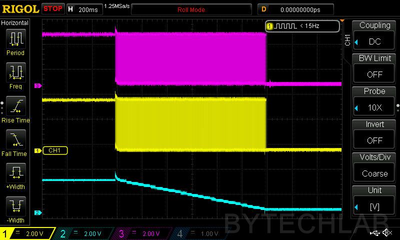
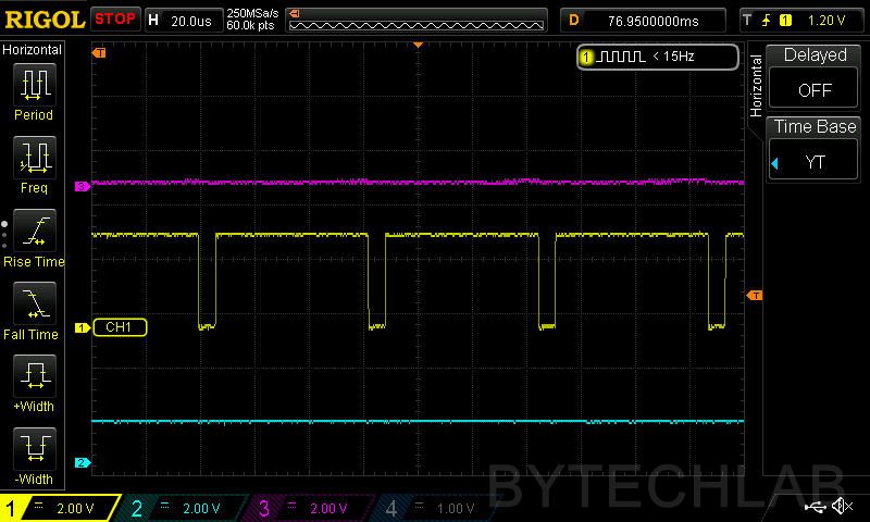
This servo was designed in the way it can rotate multiple times in one direction without losing the shaft position. It is accomplished by using two different feedback signals. First one comes from quadrature encoder and second one form the potentiometer. The potentiometer gives a position which is relative to the serwo case, I mean that we can “home” the servo shaft to a known angle with use of this signal. But there’s just one problem, as I’ve found out that the potentiometer doesn’t work in the full 360 deg range. The quadrature encoder can be used for measuring the motor speed as well as tracking the position of the shaft during multiple rotation movements (It boils down to counting pulses coming from the encoder). When we know how many pulses per revolution this encoder generates, we can easily calculate the total angle relative to the homed position (for ex. 720 deg.). In the factory-made software the potentiometer was probably used for checking the angle of the shaft during power up of the serwo, then everything was initialized with use of this value.

MOTOR & H-BRIDGE

The motor part number is FAULHABER 2232DBHHO, unfortunately I haven’t found anything about it on the Internet. Therefore , I don’t know any parameters of it. The only thing that I really know is that it is a DC motor with embedded quadrature encoder. I don’t know what’s the resolution of this encoder, I just haven’t figured it out yet.
The motor is being driven by a standard H-bridge (as described above) , you can find how the half-bridge drivers are connected down below (I don’t know the exact values of the components, as I said before , I would have to de-solder them to make a proper measurement). I won’t go any deeper into explaining how the driver works – you can find everything in the DS.

NEW CODE FOR XMEGA16D4-AU
I’ve written a super simple code to make the whole thing work as a standard serwo with UART interface. I’ve used potentiometer to get actual position of the main shaft which is relative to the servo case. It is a good thing, because we certainly want to know at what angle the motor shaft is an a given moment. I haven’t implemented encoder handling yet, because of that serwo can move only form 0 to about 330 degrees. I haven’t implemented any PID controller for driving the motor because I don’t have time to play with this servo any more.
I’ve pasted all of the code down below, really nothing special , just some peripheral initialization and other basic functions. I’ve added comments to most of the code to help you with understanding how the whole thing works.
Peripherial init functions & other
#define  F_CPU    32000000UL // 32MHz
#include    "Includes.h"
#define true 1
#define false 0
#define SERWO_POS_OFFSET 25
#define BAUD_9600 0xCF // 207

volatile uint8_t   RX_BUFF [100]; // UART data receive global variables
volatile uint8_t * RX_BUFF_POINTER = &RX_BUFF[0];
volatile uint8_t   RX_DATA_RDY = 0;

uint16_t   UART_SERWO_ANGLE = 200;
uint16_t   UART_SERWO_PWM =  900;
uint8_t	   START_MANEUVER = false;

volatile uint8_t send_buff [500];

void init_OSC_PLL(uint8_t pllfactor)
{
	OSC.XOSCCTRL =      OSC_FRQRANGE_12TO16_gc | OSC_XOSCSEL_XTAL_16KCLK_gc;// Set oscillator frequency and time to start
	OSC.CTRL     =    OSC_XOSCEN_bm;       // Start 16Mhz crystal
	while(!(OSC.STATUS & OSC_XOSCRDY_bm)); // Wait for crystal to stabilize
	CPU_CCP      =    CCP_IOREG_gc;        // Unlock system registers (write)
	CLK.CTRL     =    CLK_SCLKSEL_XOSC_gc; // Change clock source to crystal
	CPU_CCP      =    CCP_IOREG_gc;	      // Unlock system registers (write)s
	CLK.PSCTRL   =    CLK_PSADIV_1_gc;    // Set system clock prescaler to 1
	OSC.CTRL     &=   ~OSC_PLLEN_bm;      // Disable PLL
	OSC.PLLCTRL  =    OSC_PLLSRC_XOSC_gc | pllfactor; // Select crystal as PLL clock source
	OSC.CTRL     =    OSC_PLLEN_bm;       // Enable PLL
	while(!(OSC.STATUS & OSC_PLLRDY_bm)); // Wait for PLL to stabilize
	CPU_CCP      =    CCP_IOREG_gc;       // Unlock system registers (write)
	CLK.CTRL     =    CLK_SCLKSEL_PLL_gc; // Change clock source to PLL
}
void init_ADC(void)
{
	ADCA.CTRLA = ADC_ENABLE_bm; // Enable ADC
	ADCA.PRESCALER = ADC_PRESCALER_DIV256_gc; // Set clock prescaler
	ADCA.REFCTRL = ADC_REFSEL_AREFA_gc; // Use external reference voltage (PA0) - 3V
	ADCA.CH0.CTRL = ADC_CH_GAIN_1X_gc | ADC_CH_INPUTMODE_SINGLEENDED_gc;// Single ended mode, unsigned measurement
	ADCA.CH0.MUXCTRL = ADC_CH_MUXPOS_PIN2_gc; // Take measurement from PA2 pin
	ADCA.CH0.INTCTRL = 0 ; // No interrupt
}
void init_PMIC(void)
{
	sei(); // enable global interrupts
	PMIC.CTRL = PMIC_LOLVLEN_bm|PMIC_MEDLVLEN_bm;//|PMIC_HILVLEN_bm;// Enable low and med piority interrupts
}
void init_TIM_0C(void)
{
	TCC0.CTRLB        =    TC_WGMODE_DS_TB_gc|TC0_CCAEN_bm|TC0_CCBEN_bm;// DS BOTH Dual slope PWM mode,Enable outputs
	TCC0.PER          =    1000; // Set timer period
	TCC0.CCA          =    0; // CHA duty cycle value form 0 to 1000, Enable one at a time, sets direction
	TCC0.CCB          =    0; // CHB duty cycle value form 0 to 1000,
	TCC0.CTRLA        =    TC_CLKSEL_DIV1_gc; // Start timer and set clock prescaler to 1 , PWM freq = 32KHz
}
void init_USART_D0(void)
{
	USARTD0.BAUDCTRLB = 0; //BSCALE is 0
	USARTD0.BAUDCTRLA = BAUD_9600; // Set baud rate to 9600
	USARTD0.CTRLA = USART_RXCINTLVL_MED_gc;  //Enable interrupts
	USARTD0.CTRLC = USART_CHSIZE_8BIT_gc; // 8 data bits, no parity and 1 stop bit
	USARTD0.CTRLB = USART_TXEN_bm | USART_RXEN_bm; // Enable receive and transmit
	PORTD.DIRSET = PIN3_bm;
}
void sendChar(char c, USART_t *_register)
{
	while( !(_register->STATUS & USART_DREIF_bm) ); //Wait until DATA buffer is empty
	_register->DATA = c;
}
void sendString(char *text)
{
	while(*text)
	{
		sendChar(*text++,&USARTD0);
	}
}
uint16_t ReadADC(uint8_t Channel)
{
	ADCA.CH0.CTRL |= ADC_CH_START_bm; // Start conversion
	while (ADCA.INTFLAGS==0);  // Wait for measurement to complete
	return ADCA.CH0RES ; // return result
}
Main loop
I’ve implemented some basic functionalities such as:
- Changing requested angle of the servo shaft ,command syntax: $XXXX\n where XXXX is angle from 200 to 4000 (I haven’t converted it to degrees – its just a value from the ADC), You can’t change the angle from 0 to 4095 because there were some issues with the voltage reading at the limits of the potentiometer angles (unstable voltage).
- Changing the PWM value so that you can change the speed at which the servo makes given maneuver, command syntax: $$XXX\n where XXX is a PWM value from 100 to 990 (just like above its just a value that is written directly to the timer register). I have also set the top and bottom boundaries over here just because the PWM can’t be too low (the motor won’t turn at all) or too high. When you increase PWM to 100% the H-bridge drivers stop working properly – they need PWM to operate correctly.
- Sending some basic control commands such as:
- Requesting the servo to send back the actual position of the shaft , it is useful if you want to check if the serwo haven’t got stuck somewhere, command syntax: $$$A\n
- Disabling and enabling the serwo motor, you may want to disable the whole thing when it is not needed to save power, command syntax: $$$X\n where X is ‘E’ for enable and ‘D’ for disable.
And that’s all 🙂
int main(void) {

	init_OSC_PLL(2);
	init_USART_D0();
	init_PMIC();
	init_ADC();
	init_TIM_0C();

	PORTB.DIR = 0b00000011; //Set ports directions
	PORTA.DIR = 0b10000000;
	PORTC.DIR = 0b00000111;
	PORTC.OUTSET = PIN2_bm;  // Set SD to 1 , enable H bridge
	PORTA.OUTCLR = PIN7_bm;  // Turn on RED LED

	uint16_t ADC_result = 0;

	while(1)
	{
			if (START_MANEUVER == true)
			{
				PORTB.OUTCLR    =   PIN0_bm; // Turn on GREEN LED
				ADC_result = ReadADC(0);
				if (ADC_result > UART_SERWO_ANGLE + SERWO_POS_OFFSET )
				{
					TCC0.CCB =  UART_SERWO_PWM;
					TCC0.CCA =  0;
				}
				else if (ADC_result < UART_SERWO_ANGLE - SERWO_POS_OFFSET)
				{
					TCC0.CCA =  UART_SERWO_PWM;
					TCC0.CCB =  0;
				}
				else
				{
					TCC0.CCA =  0;
					TCC0.CCB =  0;
				}
			}
			else
			{
				PORTB.OUTSET    =   PIN0_bm; // Turn off GREEN LED
			}

			if (RX_DATA_RDY == 1)
			{
				if ((RX_BUFF[0] == '$') && (RX_BUFF[1] != '$') && (RX_BUFF[2] != '$')) // Set current angle
				{
					UART_SERWO_ANGLE = atoi(&RX_BUFF[1]);
					if (UART_SERWO_ANGLE < 200)
					{
						UART_SERWO_ANGLE = 200;
					}
					if (UART_SERWO_ANGLE > 4000)
					{
						UART_SERWO_ANGLE = 4000;
					}
					sprintf(send_buff,"#%d-[OK]-ANG VAL\r\n",UART_SERWO_ANGLE);
					sendString(send_buff);
				}
				else if ((RX_BUFF[0] == '$') && (RX_BUFF[1] == '$') && (RX_BUFF[2] != '$'))// Set current PWM value
				{
					UART_SERWO_PWM = atoi(&RX_BUFF[2]);
					if (UART_SERWO_PWM < 100)
					{
						UART_SERWO_PWM = 100;
					}
					if (UART_SERWO_PWM  > 990)
					{
						UART_SERWO_PWM = 990;
					}
					sprintf(send_buff,"#%d-[OK]-PWM VAL\r\n",UART_SERWO_PWM);
					sendString(send_buff);
				}
				else if ((RX_BUFF[0] == '$') && (RX_BUFF[1] == '$') && (RX_BUFF[2] == '$'))// Other commands
				{
					if (RX_BUFF[3] == 'A') // Send current position
					{
						sprintf(send_buff,"#%d-[OK]-CURR ANGLE\r\n",ReadADC(0));
						sendString(send_buff);
					}
					else if (RX_BUFF[3] == 'E') // Enable servo
					{
						START_MANEUVER = true;
						sprintf(send_buff,"#%d-[OK]-MOVE ENABLED\r\n",START_MANEUVER);
						sendString(send_buff);
					}
					else if (RX_BUFF[3] == 'D') // Disable servo
					{
						START_MANEUVER = false;
						sprintf(send_buff,"#%d-[OK]-MOVE DISABLED\r\n",START_MANEUVER);
						sendString(send_buff);
					}
				}
				RX_DATA_RDY =0 ;
			}
			PORTB.OUTSET    =   PIN1_bm; // Turn off BLUE LED
	}
}
UART interupt routine
Im receiving the whole command from UART interface to the RX_BUFF just with a simple interrupt routine. It puts new characters in to RX_BUFF array until it finds a ‘\n’ character which indicates end of a command. When it finds “\n” character it also sets the RX_DATA_RDY flag.
ISR (USARTD0_RXC_vect){
	uint8_t rcv_char = USARTD0.DATA;
	PORTB.OUTCLR    =   PIN1_bm; // Turn on BLUE LED
	if (rcv_char == '\n') // detect last character
	{
		*RX_BUFF_POINTER = rcv_char;
		RX_BUFF_POINTER= &RX_BUFF[0];
		RX_DATA_RDY = 1;
	}
	else
	{
		*RX_BUFF_POINTER = rcv_char;
		RX_BUFF_POINTER++;
	}
}
MORE PHOTOS


SUMMARY
Just to sum it up all, I’m very happy that I was able to successfully finish reverse engineering of HerkuleX DRS-0602 servo. It doesn’t have as many functionalities as it had with the factory-made firmware but at least it works. At this stage it is very easy to add your own functionalities. Maybe I’ve inspired you to reverse-engineer some stuff – it’s really not as hard as it looks. Unless you find a “no-name ASIC” inside.