
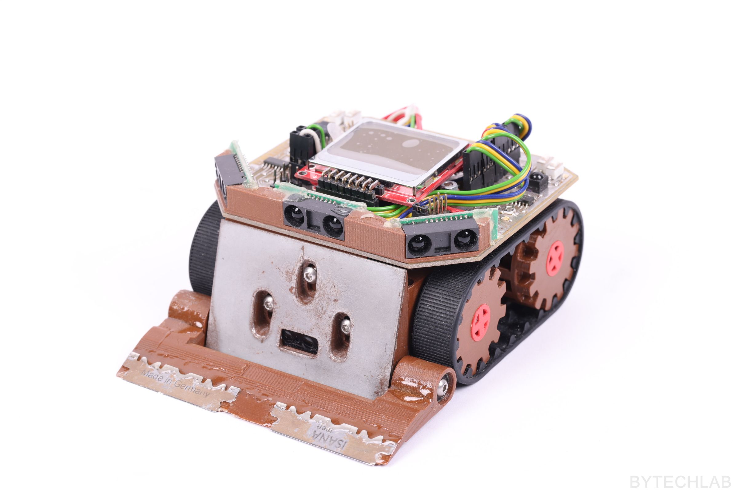
Mini Sumo Robot Bullet XT took part in several competitions but due to one mistake in mechanical design it was too easy to defeat it during fight on dohyo. But you know, I don’t give up so easily – I’m planning to try out new ideas and designs.
I think that the next iteration of this robot shouldn’t have any design flaws anymore. The whole robot including the design process was created in about 2 or 3 weeks.
Below in this little article/post I will try to describe my build and the most important mistakes I’ve made in it.
MCAD DESIGN
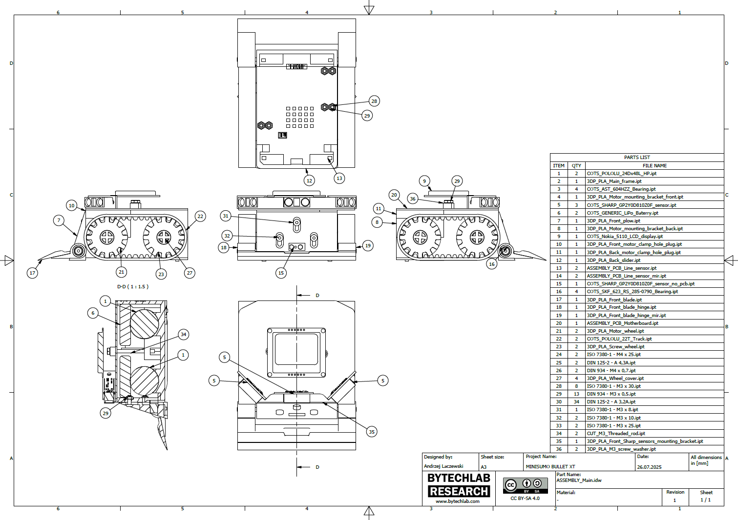
The project was created quite quickly in Autodesk Inventor. During design I took into account the possibility of adjusting the plow to fit the dohyo surface. It was a big mistake but I’ll describe it later on. The motors are mounted with 3D printed clamps that squeeze them with use of 4 M3x30 bolts. In this project I’ve also included a sharp scraper plate attached with 4 ball bearings. It was designed to “unfold” during the sudden movement at the start. After some calculations, the predicted weight was within 450 grams, in fact the real weight of the whole robot was about 490 g.
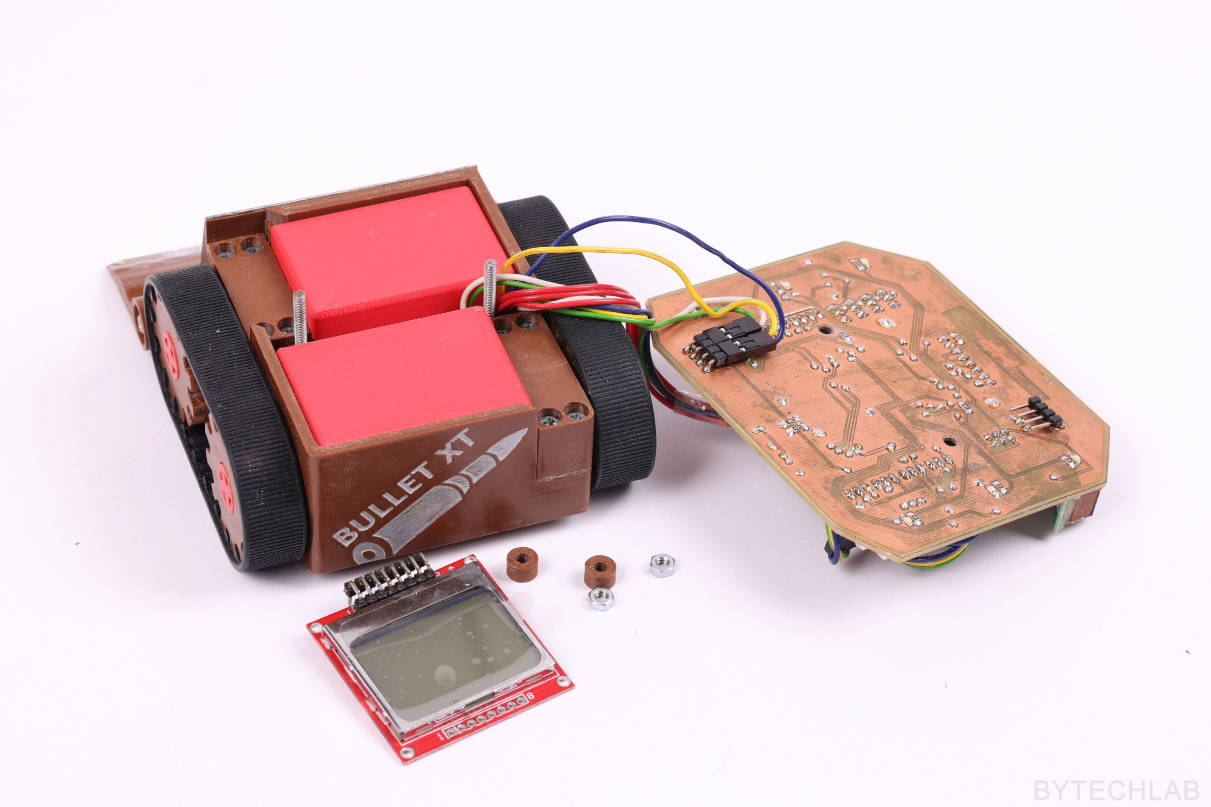
In the render below you can see most of the parts from which robot is made of:
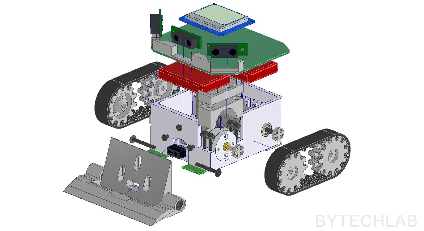
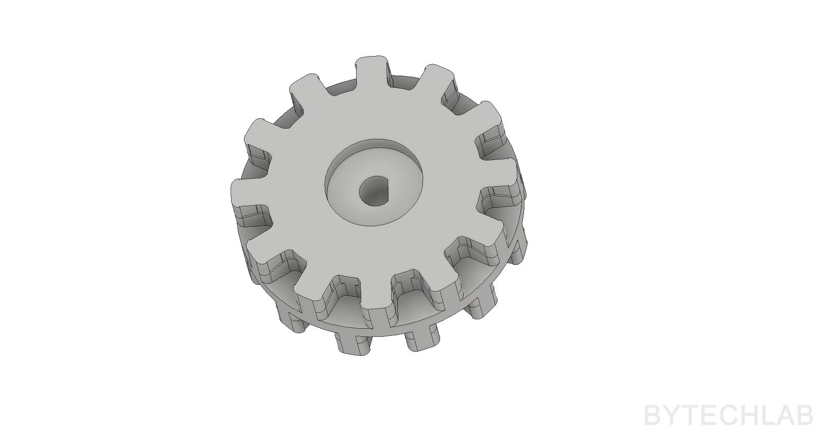
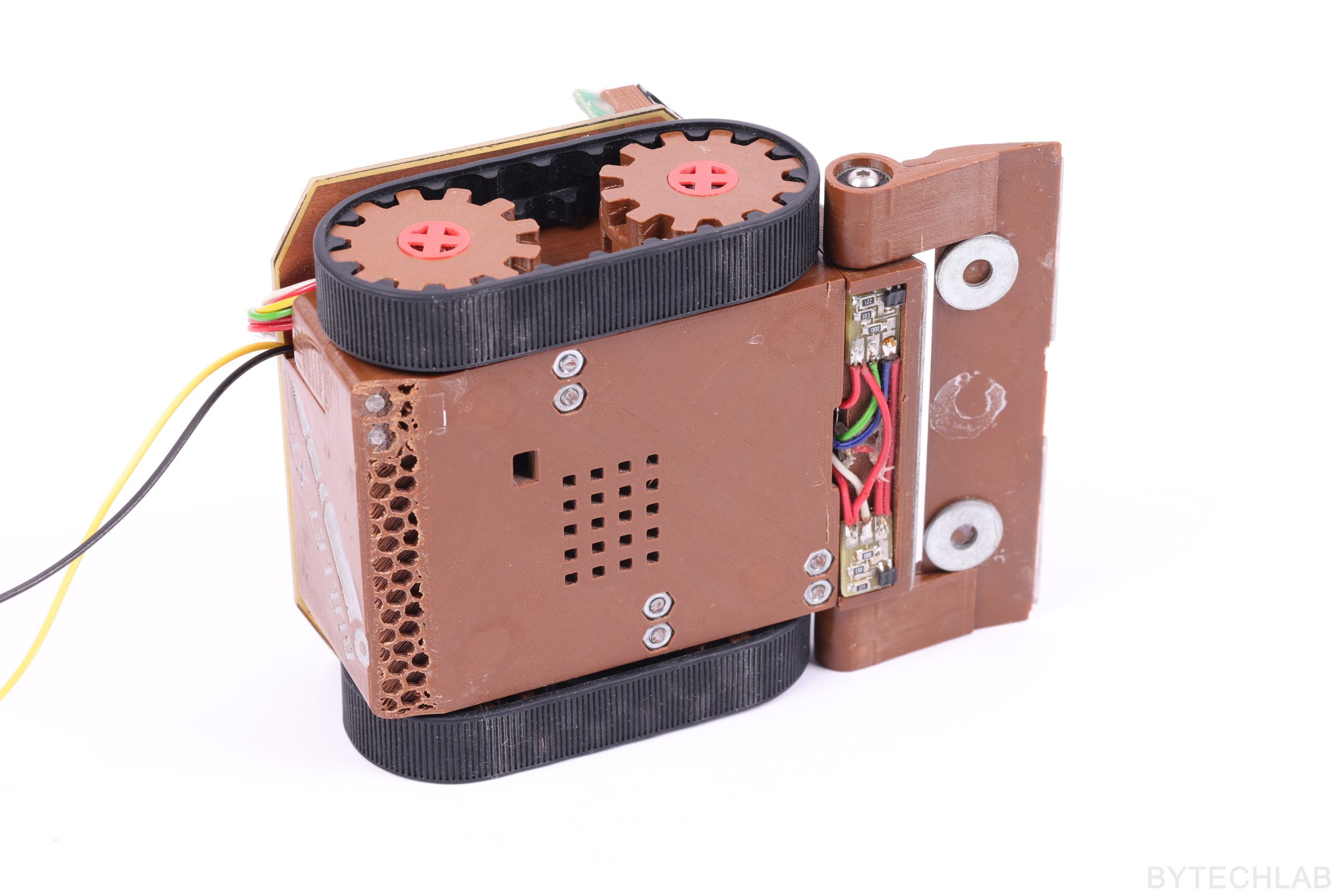
As the factory made Pololu gear wheels had wrong diameter D-shaped holes (they fit to pololu micro-gear motors) I had to redesign them. I’ve also improved some details in these gears to make them easier to 3D print.
In the GitHub repository (MCAD folder) you can find the following files:
- Autodesk Inventor project,
- Exported STL files for 3D printing,
- Exported STEP file of the whole assembly,
- Exported PDF file with assembly drawing, BOM and assembly instructions,
- Exported assembly renders,
ECAD DESIGN
The PCB’s were designed in Autodesk Fusion 360 (Eagle) software.
The following components were used:
- Main microcontroller – Xmega128A3U – It has many useful hardware peripherals ,
- Motor controllers – TB6612FNG – They are connected in parallel due to the high peak current rating of the motors,
- User menu – Tact-switches and Nokia 5110 LCD,
- Remote control – TSOP Series infrared receiver – Remote triggering ( this feature was never implemented in the code ),
I have etched the PCB’s by myself with use of photochemical method (2 layers). I have even coated the bare copper with Lichtenberg alloy to prevent it from oxidizing.
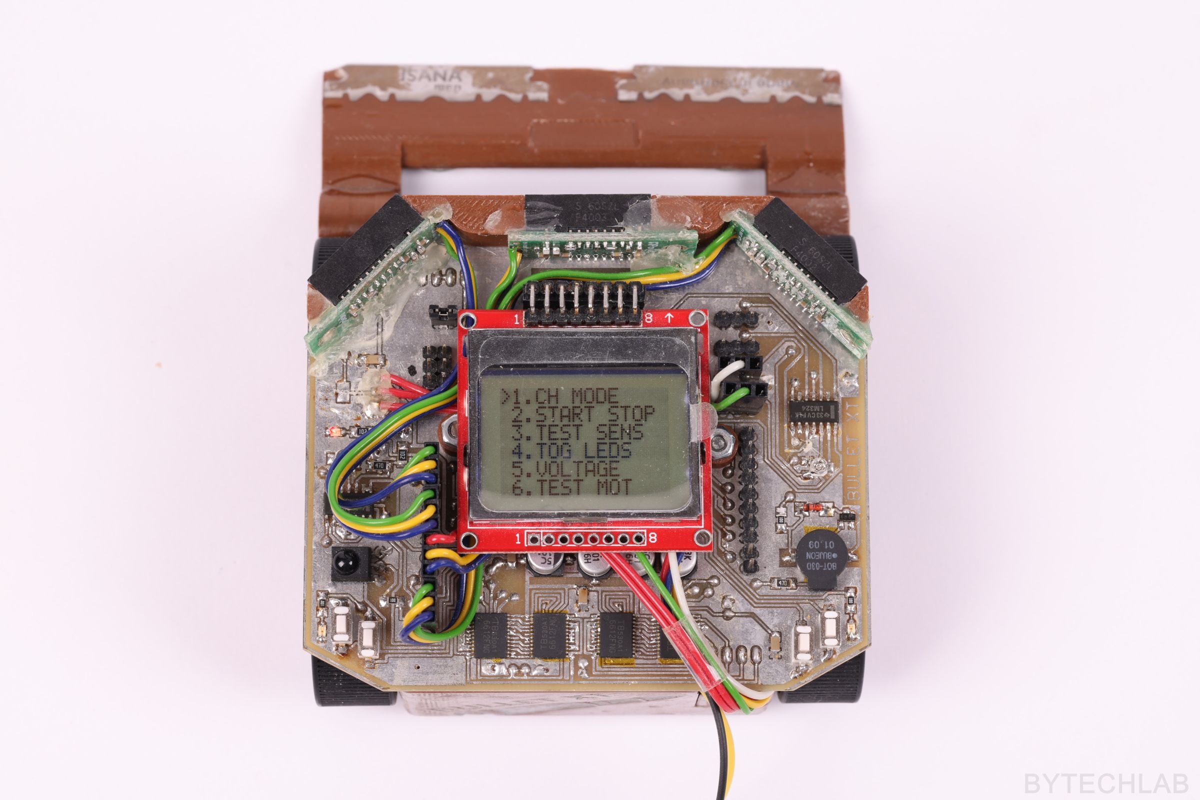
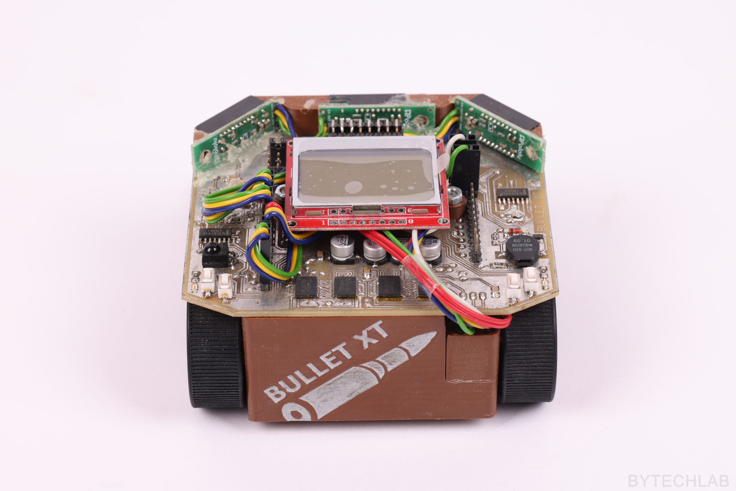
On the photo below you can see the whole menu (fighting mode, testing the sensors, turning on/off the lights, checking the battery voltage and testing the motors):
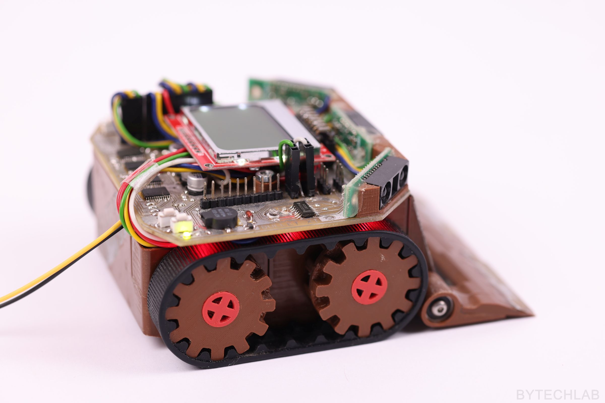
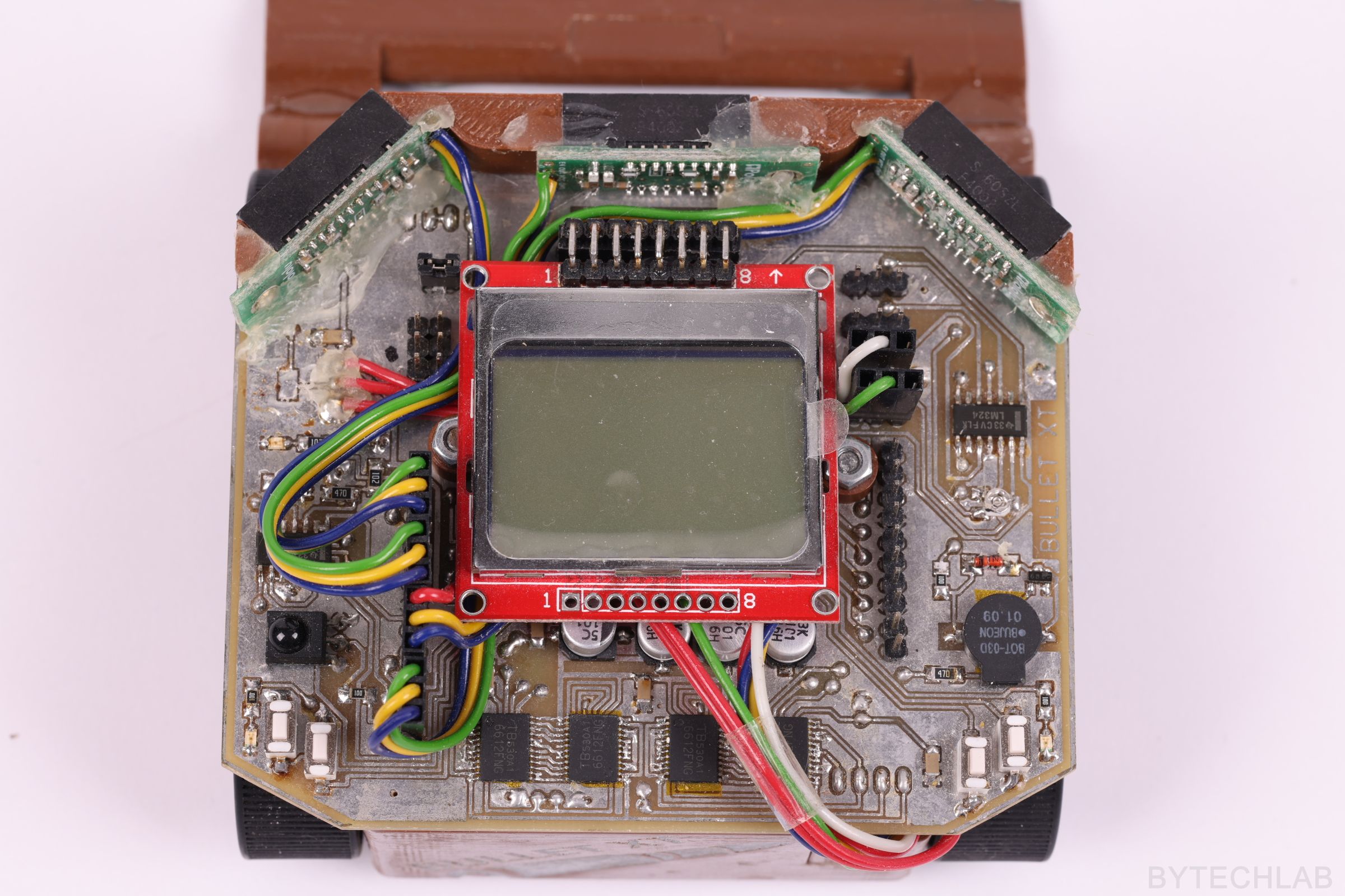
I’ve also added some LED,s on the corners and under the PCB just to improve the overall external appearance – on the photo below you can see the highlighted tracks:
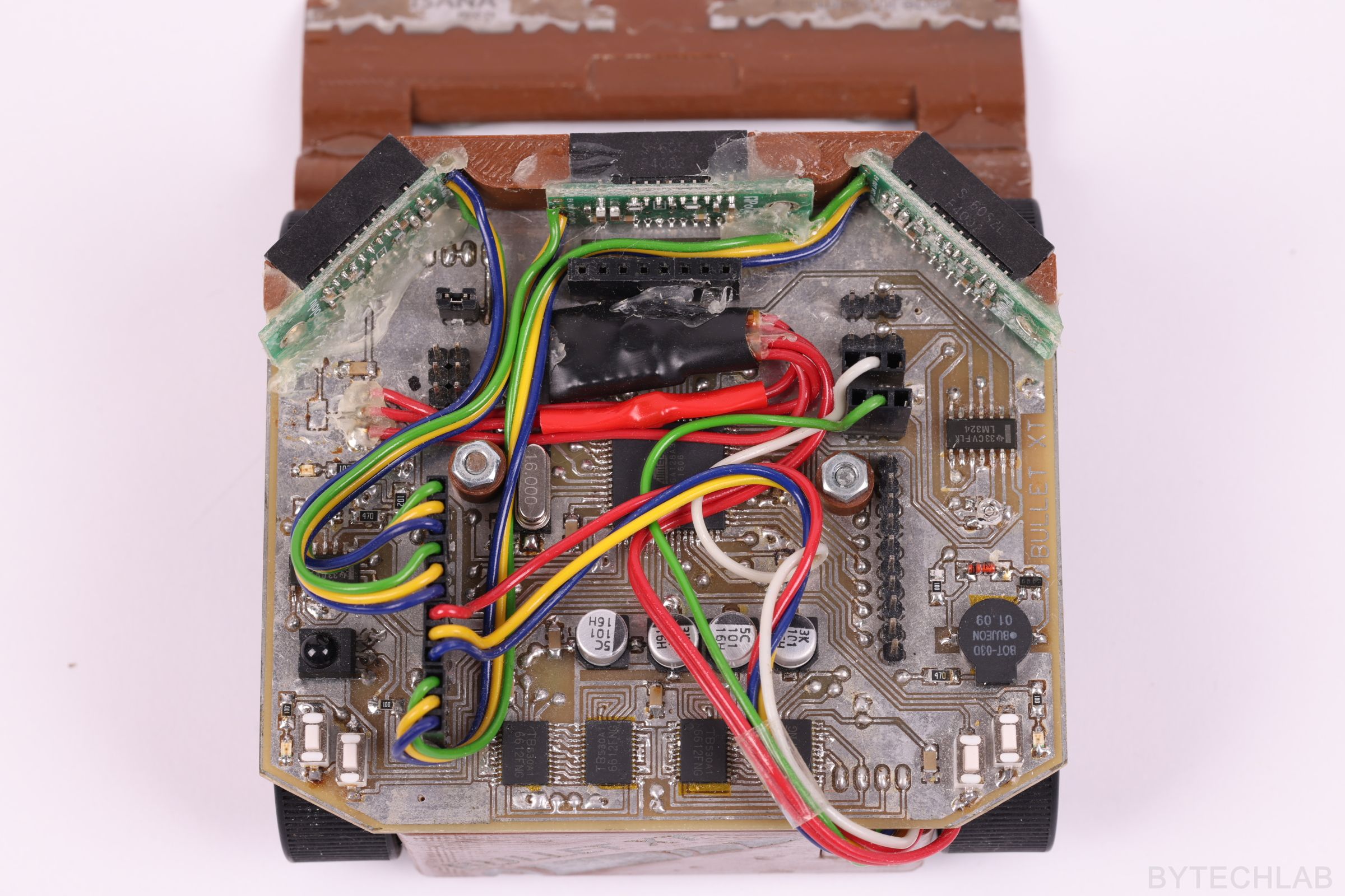
Unfortunately there’s some cable spaghetti under the LCD:
TESTS
To test the robot I have printed a doyho ring, that I’ve later laminated to increase the durability of the surface. I know what you’re thinking, “brick” tests are not the same thing as fighting a real opponent, but at least you can see more or less that everything works as it should. During the tests I’ve made some minor corrections in the code and I’ve adjusted the analog comparators responsible for detection of the doyho edge. As you can see in the video below, the robot is very fast and it very well copes with the movement of almost a 1-kg box of screws.
During the tests, the robot fell into a slip despite of using tracks with high surface grip, due to too high motor “power”. Because of this full motor power was only activated when the robot decided that the opponent is exactly in front of it. Otherwise, the robot was falling out of the ring because of high inertia and speed. To fix this issue of this I had to do a pretty complicated combat algorithm to make it work at all. During the tests, the adjustable plow caused some problems by “hooking” on the doyho.
In the menu there is an option that allows you to test all sensors in real time and adjust them to actual conditions on the ring:
Below you can also see how the user menu works:
MOTORS
I have used powerful Pololu: 25Dx48L HP motor with gearbox ratio 9.7:1 in this mini sumo robot. As it turned out later, motors with such a torque are an big overkill (these motors almost never work at full power). I think that anything from the micro series should have enough torque.
You can see some specs of these motors below:
- Nominal voltage: 6 V
- Dimensions: 25D x 48L mm
- Weight: 82 g
- Shaft diameter: 4 mm
- Gearbox ratio 9.7: 1
- Idle rotation at 6V: 990 rpm
- Idle current (6V): 550 mA
- Peak current: 6 A
- Torque: ~ 0.27 Nm
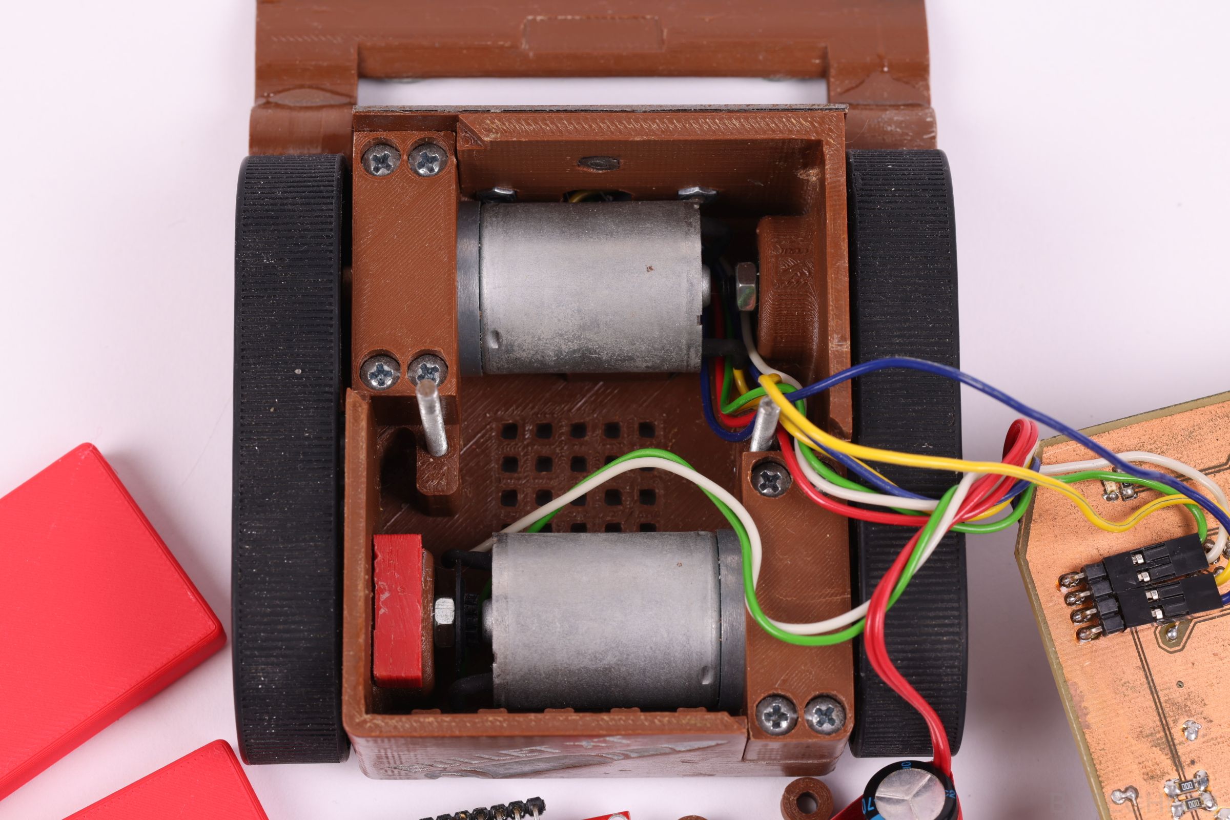
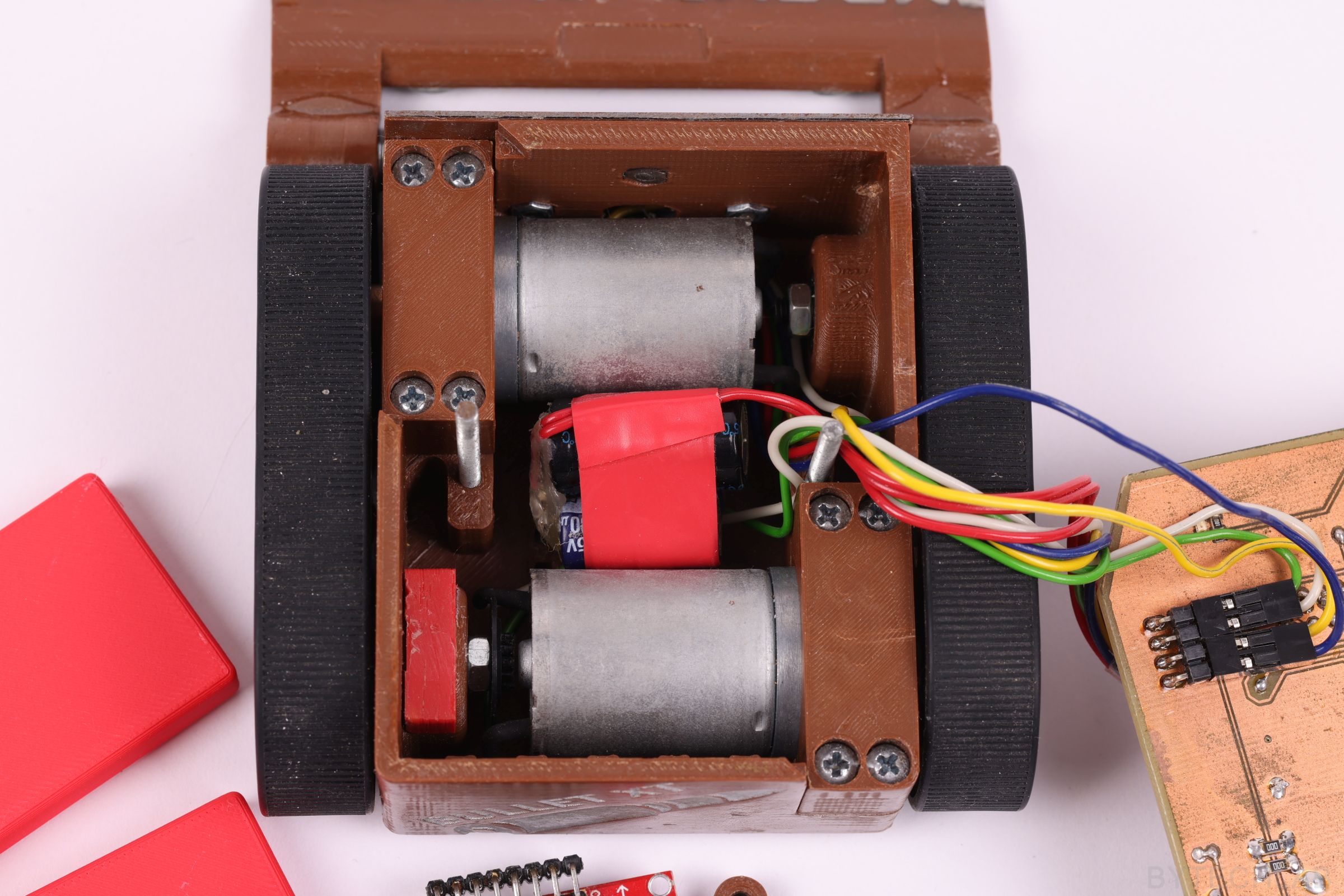
In the picture below you can see the encoder , motors and capacitors that were added later to stabilize the supply voltage:
The peak current turned out to be a big problem, when starting from idle, these motors pull 6 A each, so together they draw about 12 A. The first channel on the oscilloscope shows the voltage drop on the Li-Po battery when one motor starts (as you see the drop is quite serious, about 2 volts).
Every time when motor started from idle ,the microcontroller was restarting (due to BOD enabled). To fix this issue a large bank of electrolytic capacitors and & supply isolation diode were added. After isolating the logic circuit supply voltage from the motors supply voltage with the diodes and replacing the linear regulator with step up / step down converter everything worked as it should.

On the second enlarged oscilloscope screenshot you can see the H-bridge PWM switching noise (motor supply voltage):

SENSORS
My favorite digital sensors Sharp GP2Y0D340K are no longer available so I had to find something else. I’ve decided to use fast analog Sharp’s GP2Y0A60SZLF (10-150cm) which are very similar to the 340K’s. These sensors work just fine, but are not as good as the digital GP2Y0D340K.
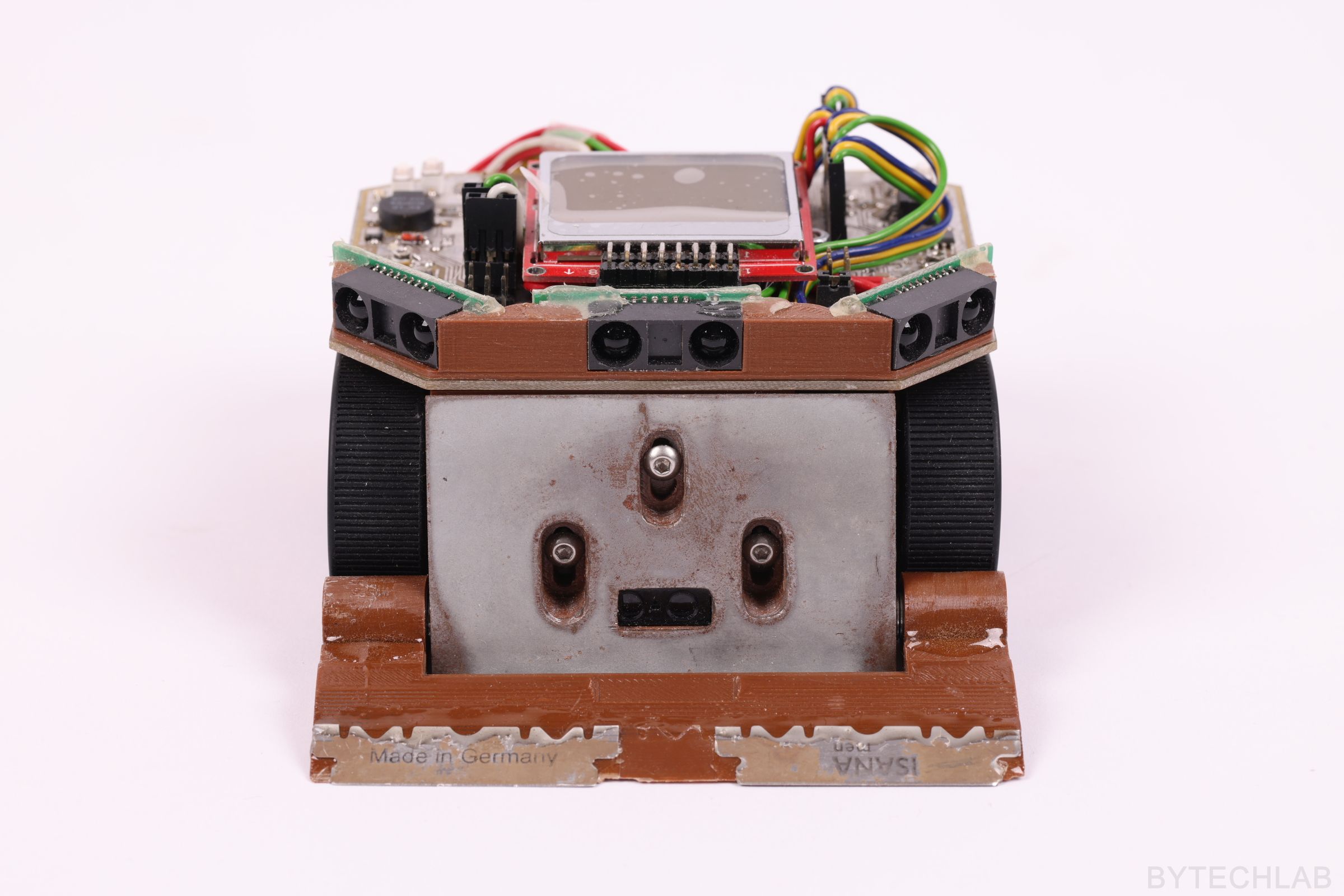
Sometimes they don’t keep up with the detection of the fast moving opponent. As a dohyo edge line sensors I’ve used KTIR0711S proximity sensors. In addition, a Sharp GP2Y0D810Z0F (10cm digital distance sensor) was placed in the middle of the plow to check if the opponent is currently in front of it (to decide about applying maximum power to the motors).
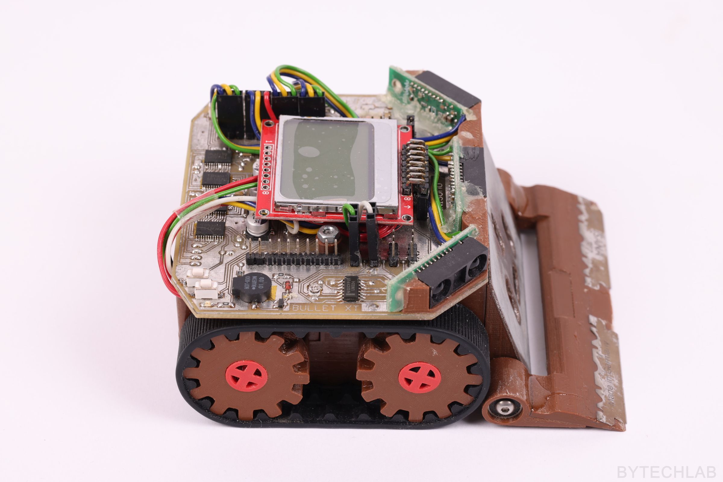
Line sensors have been mounted only under the front plow:
BATTERIES
There are 4 Li-Po 3.7V 700 mAh batteries connected in parallel (2S2P). The batteries connectors are nicely hidden under the PCB.
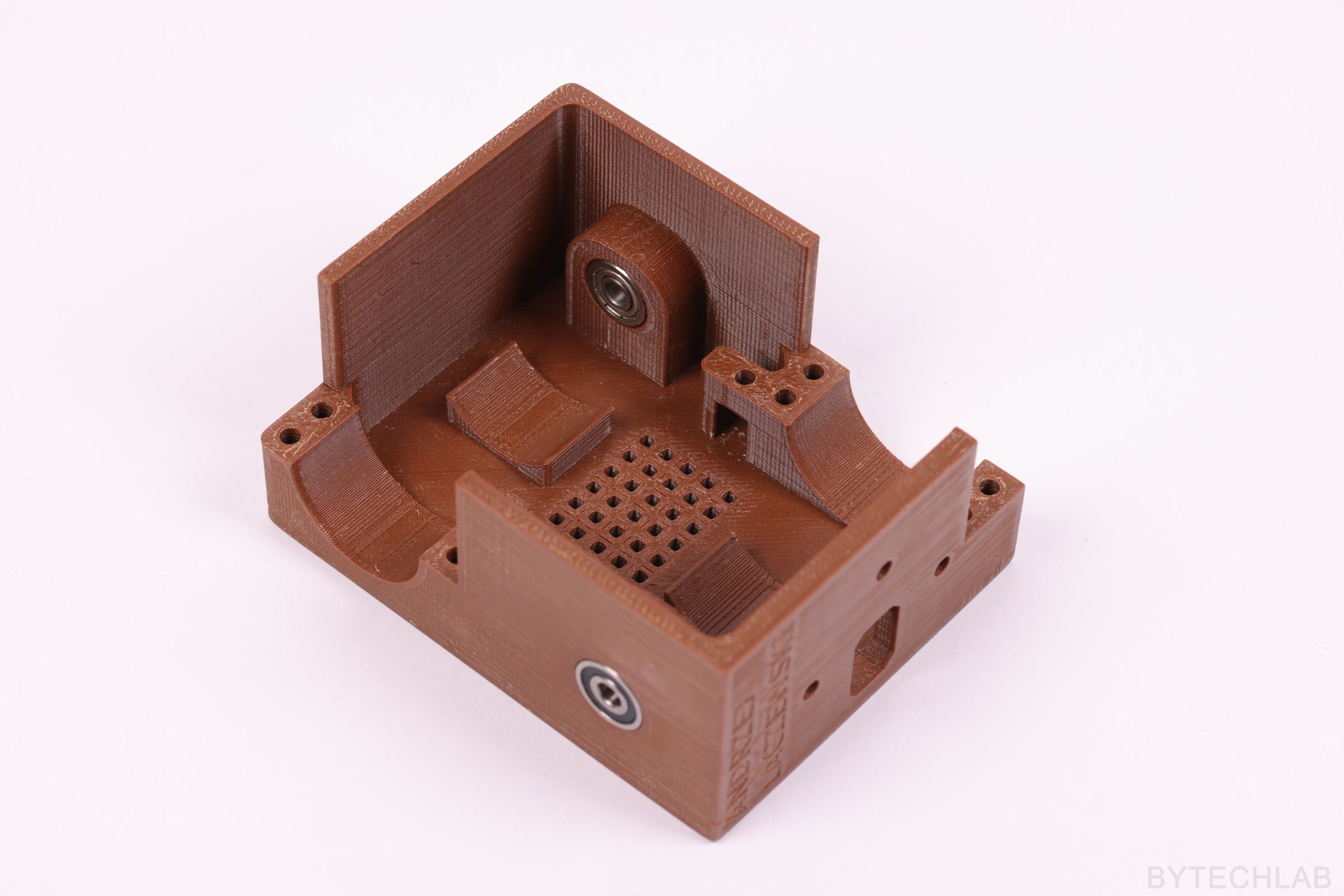
3D PRINTING
Almost all of the parts used in the mini sumo robot were 3D printed from ABS filament. The photo below shows the main 3D printed frame, motors mounting points and the the “idler gear wheels” bearing blocks.
The 3D printed plow was laminated with epoxy resin and steel plate to reinforce it. Thin razors were glued to the 3D printed “scraper”. Unfortunately, this idea didn’t worked as expected, because the scraper doesn’t want to lay flat on the doyho surface by itself. I’ve been trying to add some weight to it, but it didn’t worked either…
ADDITIONAL PHOTOS
SUMMARY
This mini sumo robot works very nicely, but the front plow sticks too poorly to the surface of the Doyho. Because of this it is very easy for the opponent to pry it up from the front. Prying it up just a little causes it to lose traction – because of this it can be pushed out of the ring very easily.
Certainly I need to re-design the main frame to accommodate it to a better plow made of sharp and “low profile” blade which could be pushed under the opponent easily.
DESIGN MISTAKES:
- The plow doesn’t lay flat on the Doyho surface,
- The scraper with razors does not work as intended,
- Major issues with power supply section,
- Motors with too high current draw were used,