
This Measurement Rail For SMD Parts is a part of SMD parts sorting machine project. It will be used to sort SMD parts by their size,shape and most importantly by their values and other important parameters. As the name suggests this measurement rail is responsible for measuring parameters of SMD components (resistance, capacitance, ESR, inductance, etc.). The whole thing was designed in a way that it can be fully automated. The measurement rail will be fed with parts from DIY Bowl Feeder (one part at a time). After performing the measurement the part is moved to the further parts of SMD parts sorting machine.
This project is quite big , that’s why I’ve divided the whole topic in to smaller articles. Each bigger part of this project will have its own article. Soon I will publish one big “main” article that will contain description of the whole project, links and short descriptions of all sub-articles.
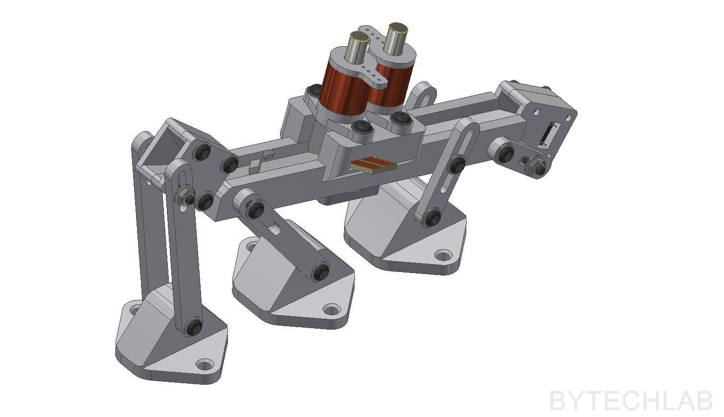
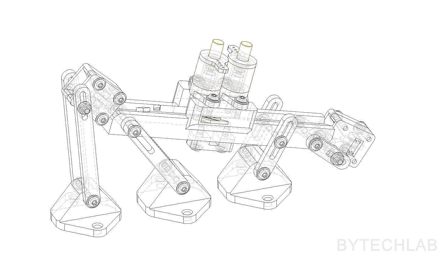
MECHANICAL DESIGN & RENDERS
As always ,I’ve designed everything in my favorite CAD software (Inventor). Designing the whole thing took me about one day.
After making first prototype I’ve made some minor changes to the project. For example I’ve modeled a slot at the bottom of the rail to allow the vibration motor to spin freely (As it turned out ,I’ve completely forgotten about it , but you know a few “scratches” with the Dremel tool solves the problem instantly).
The whole thing was designed in the way that most dimensions and angles can be adjusted (to allow the correct operation of the whole device).
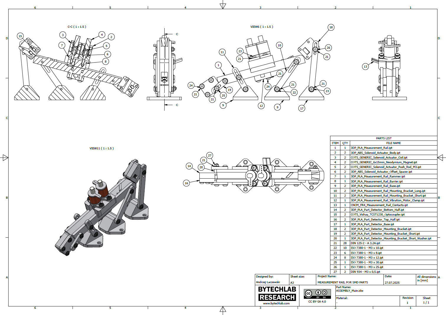
In the GitHub repository (MCAD folder) you can find the following files:
- Autodesk Inventor project,
- Exported STL files for 3D printing,
- Exported STEP file of the whole assembly,
- Exported PDF file with assembly drawing, BOM and assembly instructions,
- Exported assembly renders,
3D PRINTING PARTS
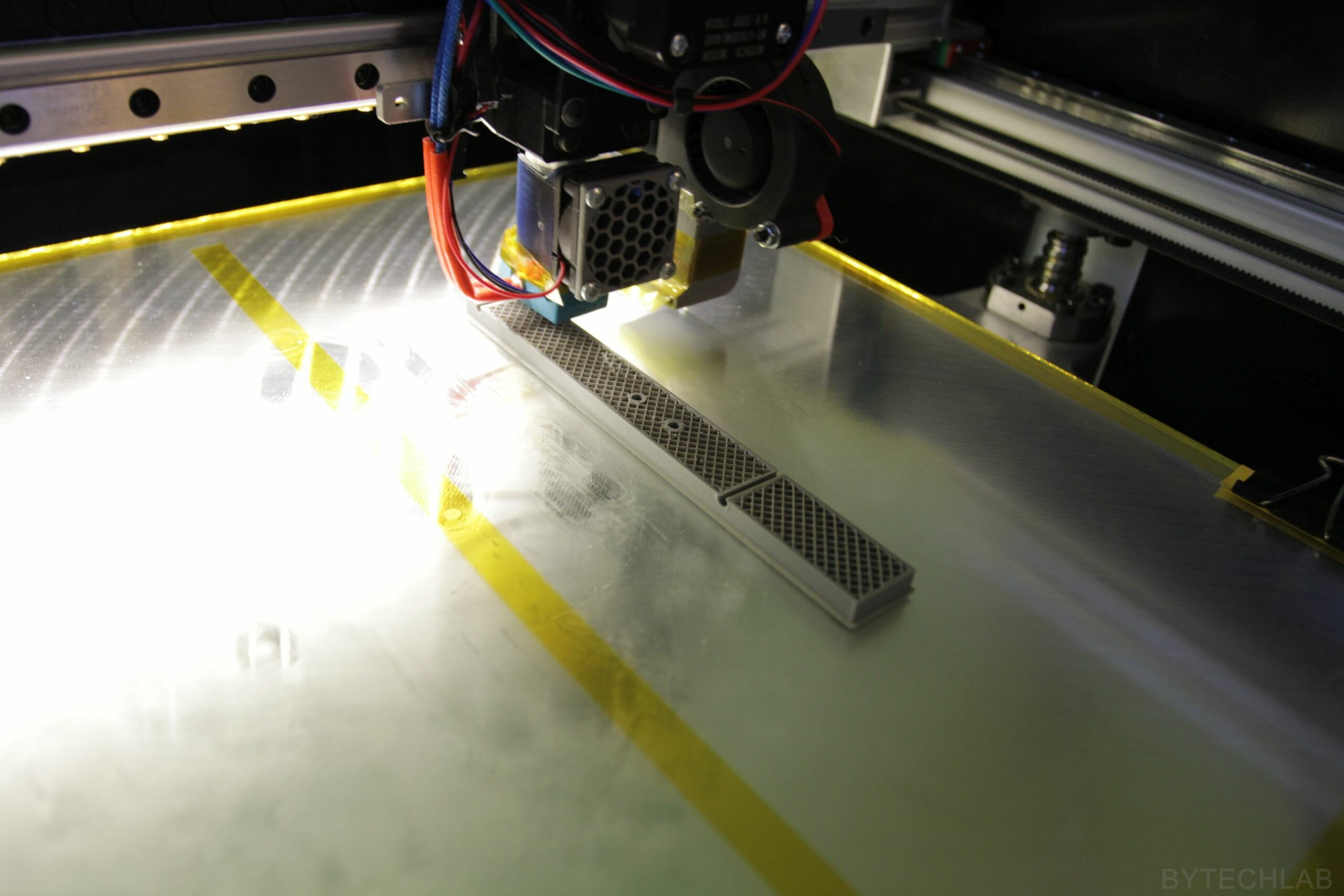
As always everything was printed on my RAPTOR XLS-360 printer. I’ve printed everything using ABS and PLA filament. Most of the parts didn’t needed any support structures so they were relatively easy to print.
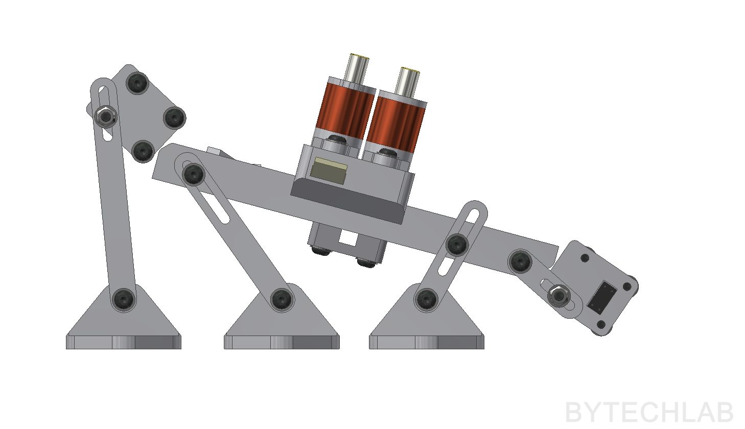
SOLENOID LINEAR ACTUATORS

The solenoid linear actuators were definitely the hardest thing to do. I started by making some simple calculations to determine the needed wire diameter. I’ve chosen 0.12 mm diameter copper wire if I remember correctly. To simplify the whole process of winding such an solenoid coil, I’ve made a drill adapter that allowed me to wind the coil relatively precisely and fast.
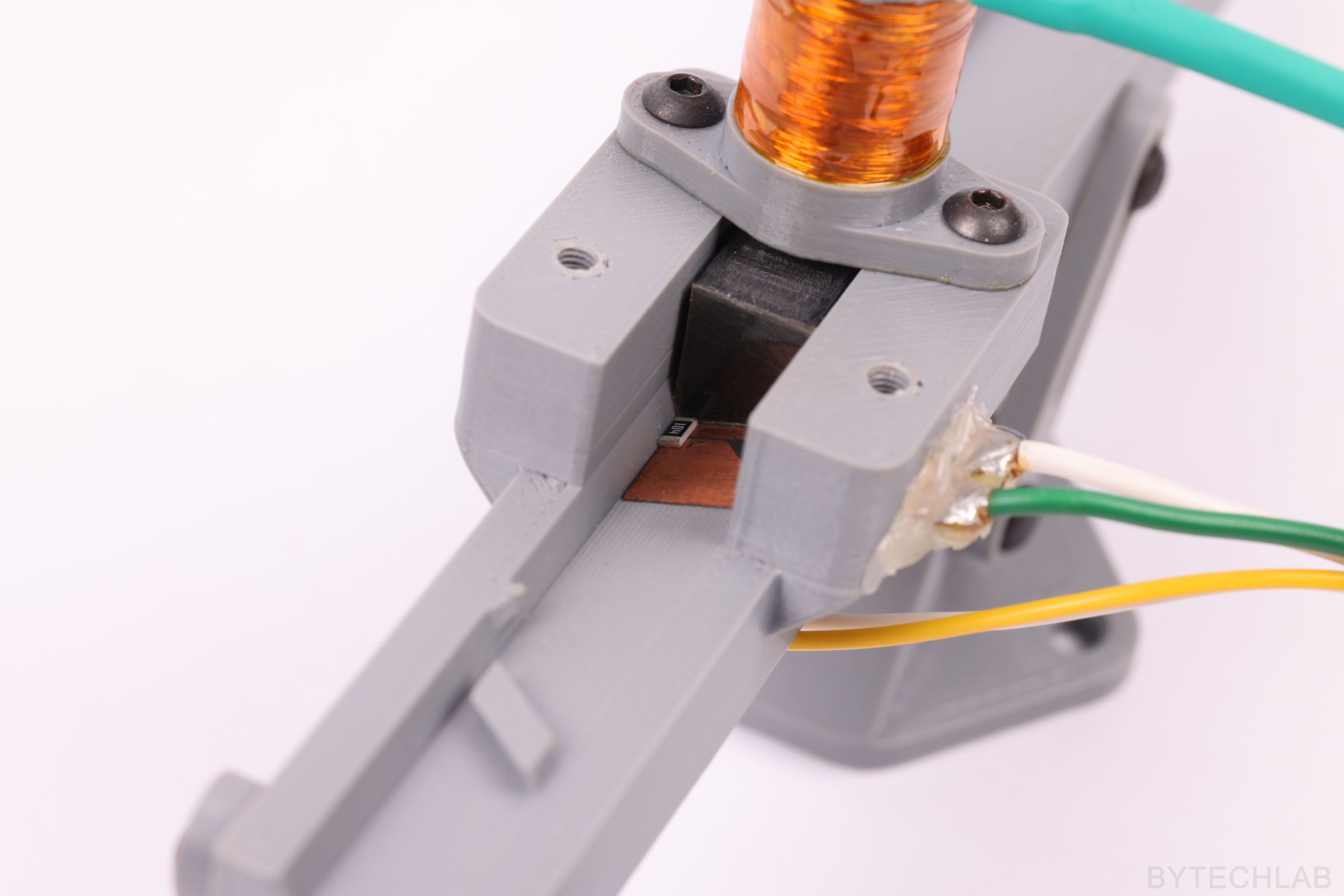
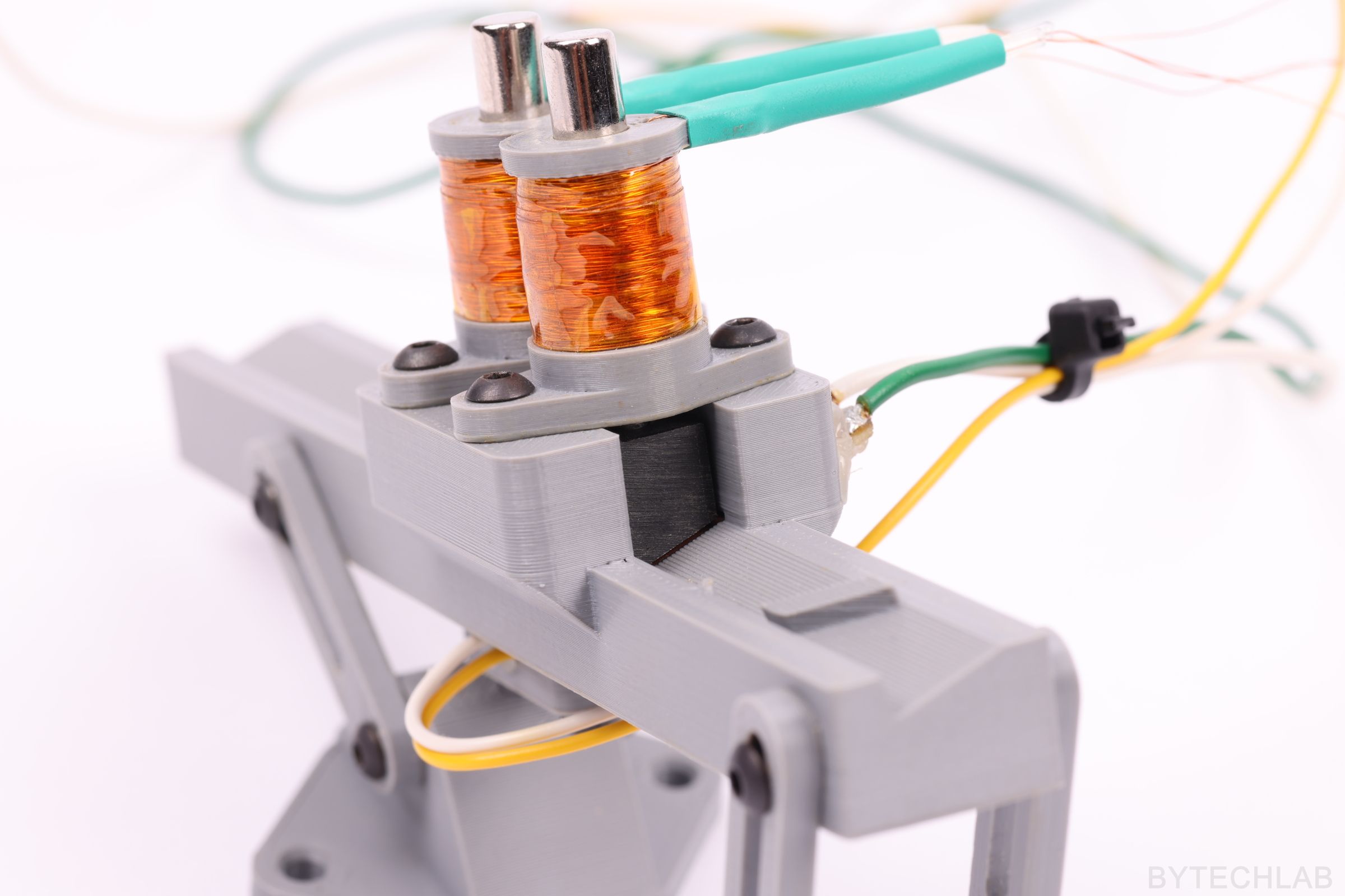
Now this is important, this actuator is quite unusual – it uses a neodymium magnet to “actuate”. The magnet allows to actuate in two directions just by reversing current flow in the coil. Because of that a return spring is not needed.
A simple H-bridge is just enough to control the whole device. The coil was designed in the way that it can operate at standard voltage of 12 volts without overheating – it is quite big problem because ABS softens in about 100 deg C. The coil was secured with a few layers of Kapton tape to ensure that it wouldn’t unwind by itself. I’ve used some heat shrink tubing to protect the copper wires from breaking off (strain relief). The whole thing works quite well, I can’t say anything bad about this design. I was thinking about using some pneumatic actuators but the cost of the whole pneumatic system would definitely blow up my wallet so I went with this cheaper option.
The solenoid linear actuator consists of the following parts:
- Main body to which the coil is wound on,
- A strong cylindrical neodymium magnet 6×12 mm,
- A coil of course,
- A M3 bolt shortened to the right length,
- An offset washer,
- And again I don’t really know how to call this part , maybe “piston” or “pushing block” (it is this fancy trapezoidal shaped part with a hole in one side of it),
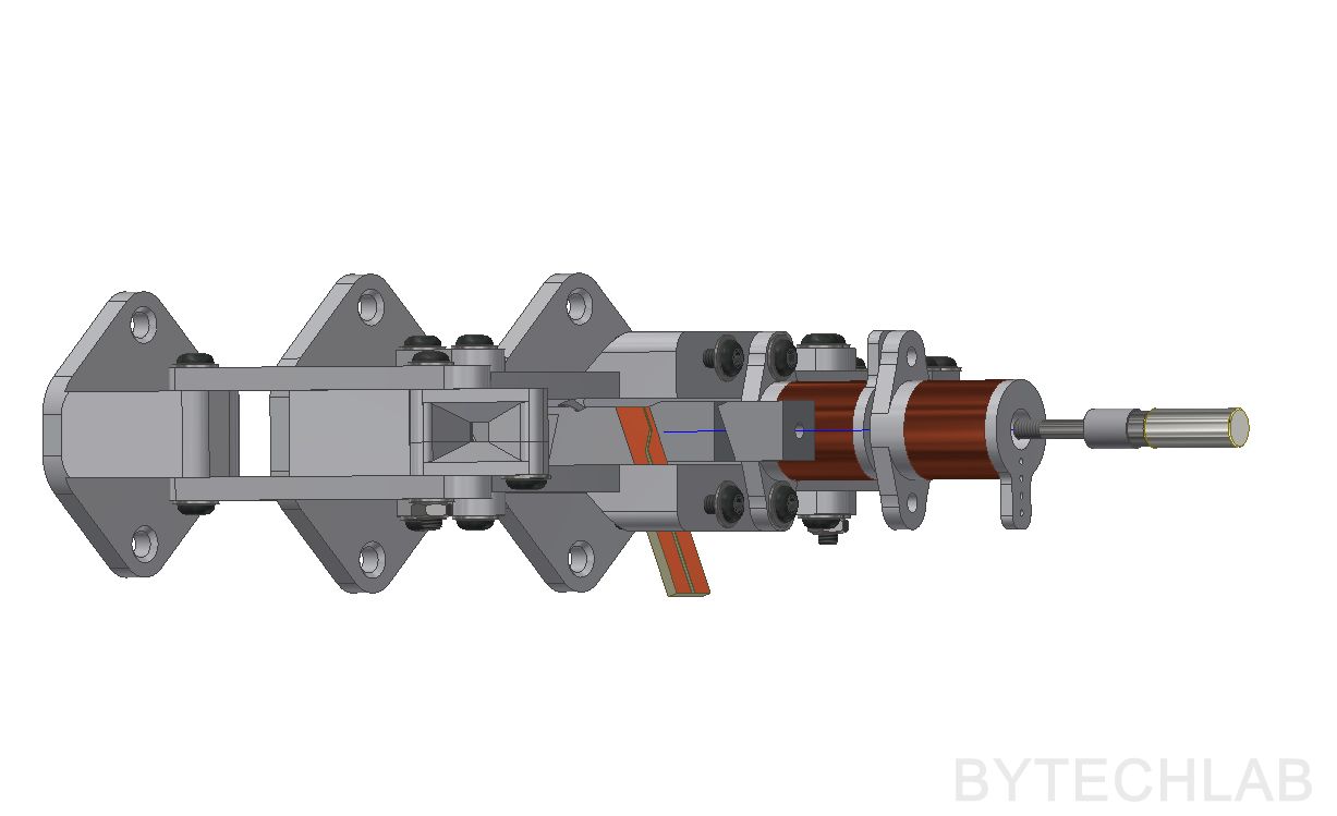
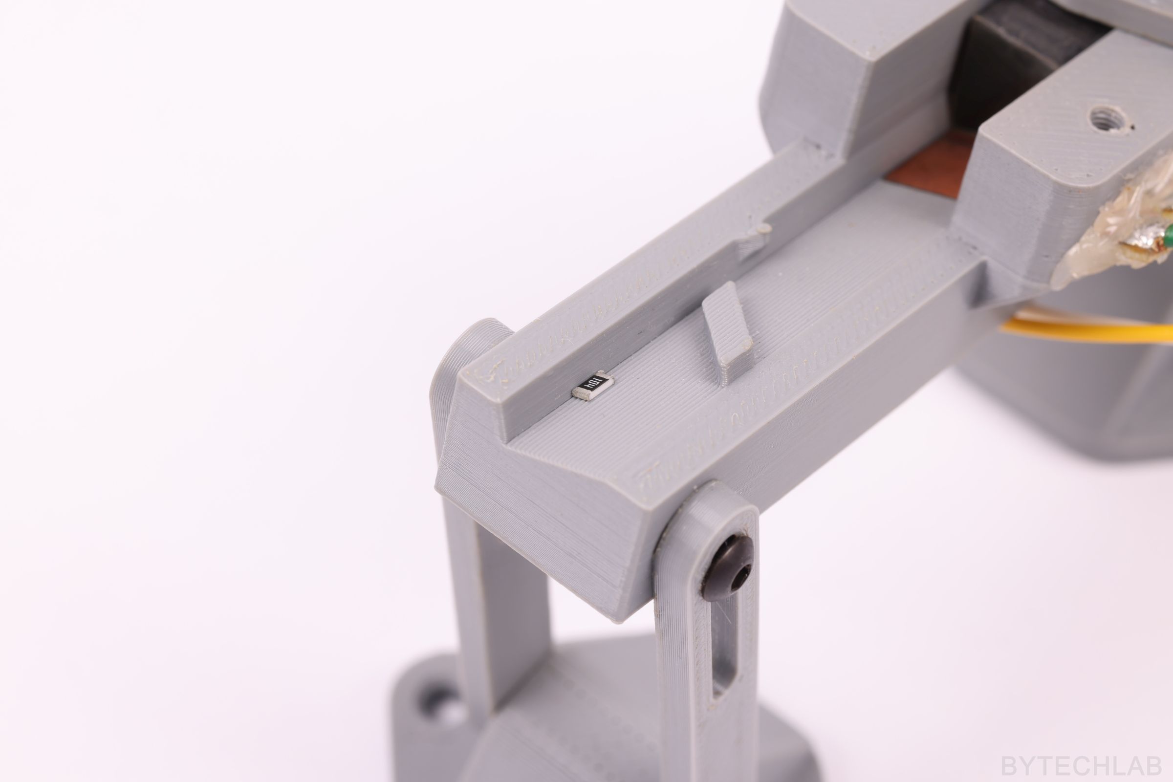
MEASUREMENT CONTACTS

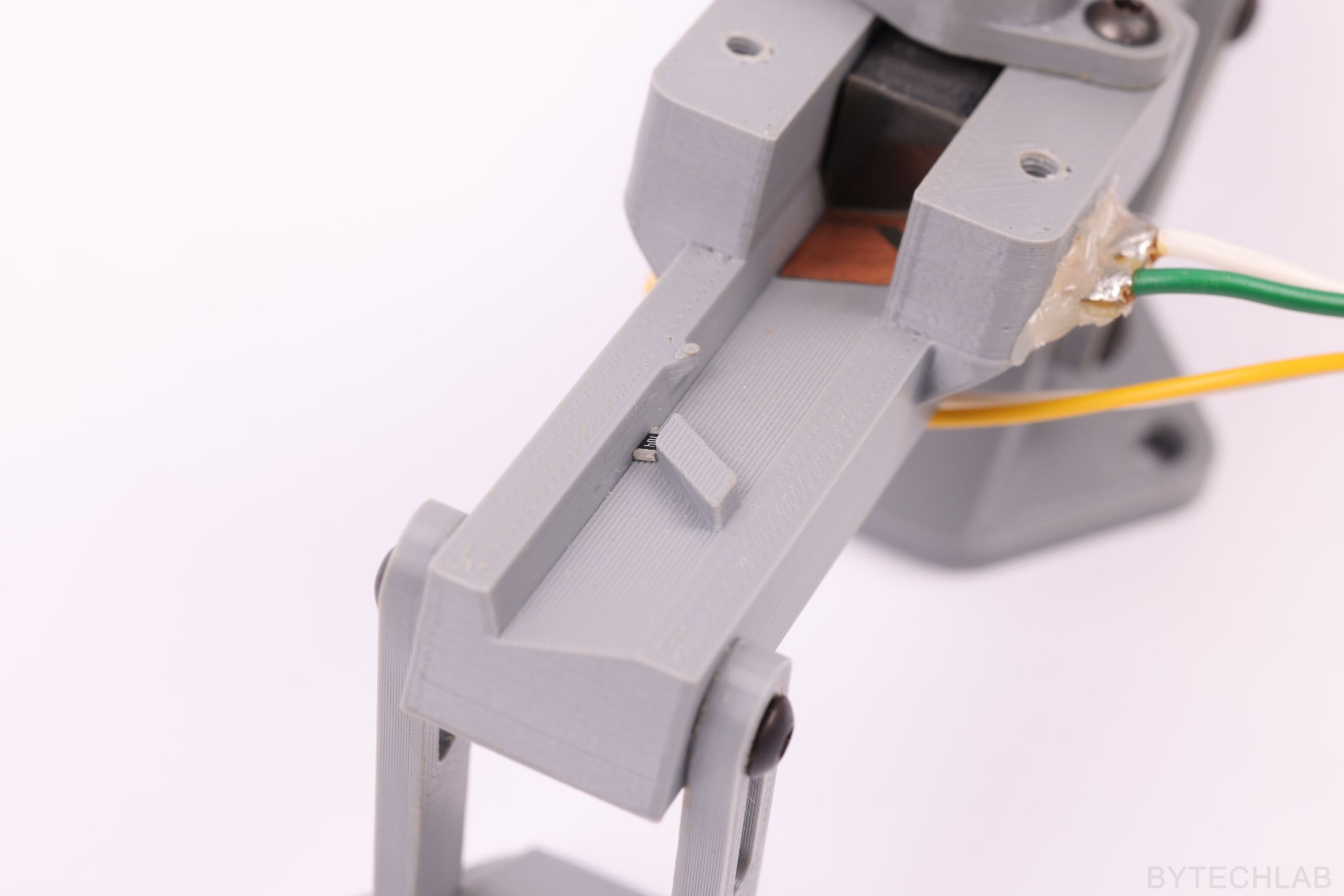
I’ve designed this simple measurement contacts in the way that they will make good contact with the SMD part itself. In the next iteration of this prototype I will definitely take the parasitic capacitance problem into account because this measurement rail will be used mainly to measure parameters of some SMD capacitors. There might be a problem with a wear of these contacts because layer of copper is quite thin on the PCB. I will fix this potential problem in the next prototype.
Firstly I have cut out a piece of PCB and later I’ve painted it with permanent marker pen. Then I scratched the painted surface with small knife to expose the copper in some places. Prepared PCB was etched in my etching tank. The water is heated and mixed with air bubbles which come from an aquarium pump. Really nothing special. I’m using a Sodium Persulfate (Na2S2O8) solution instead of ferric chloride that is quite “messy”.
HOW DOES IT WORK?
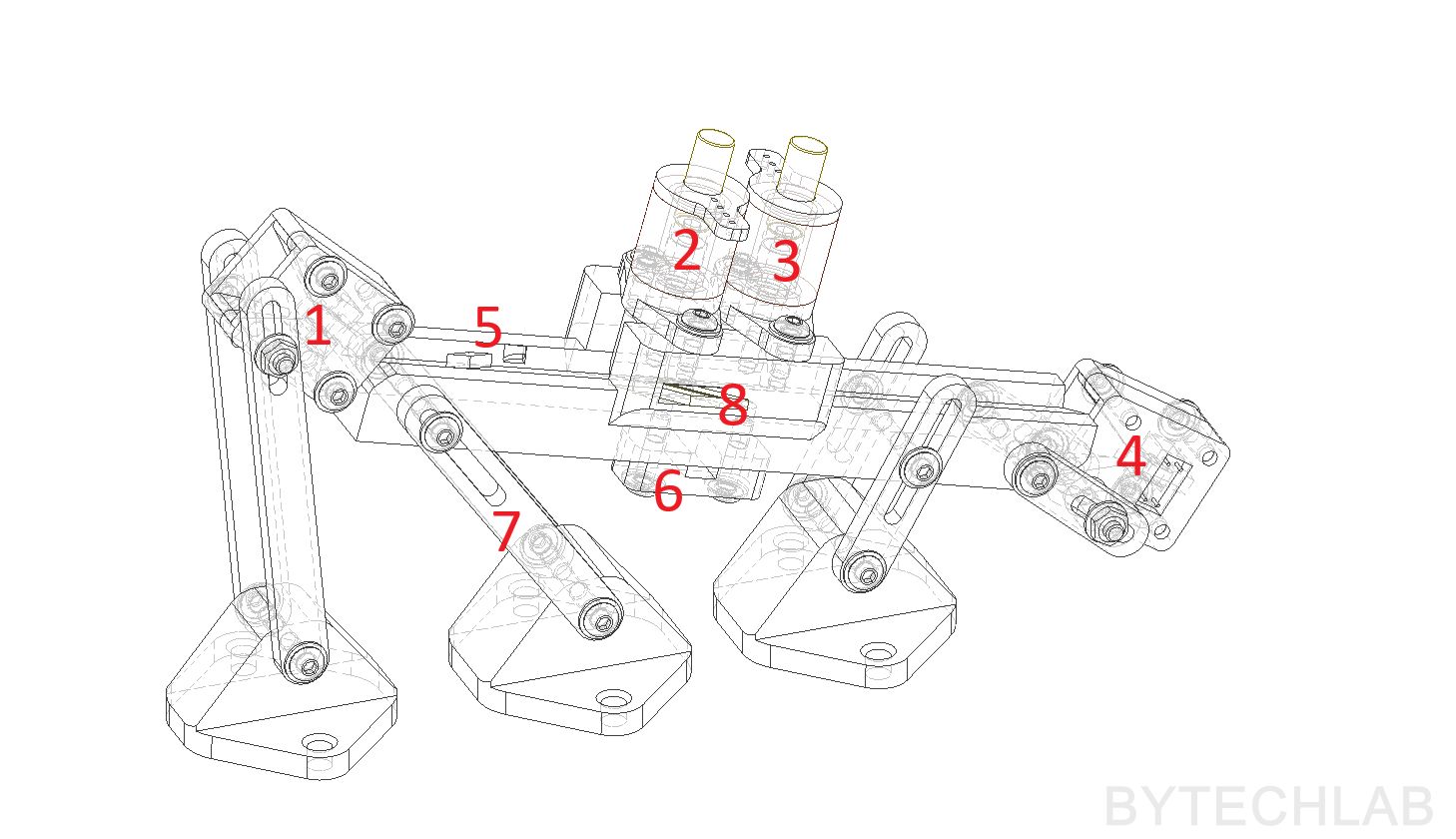
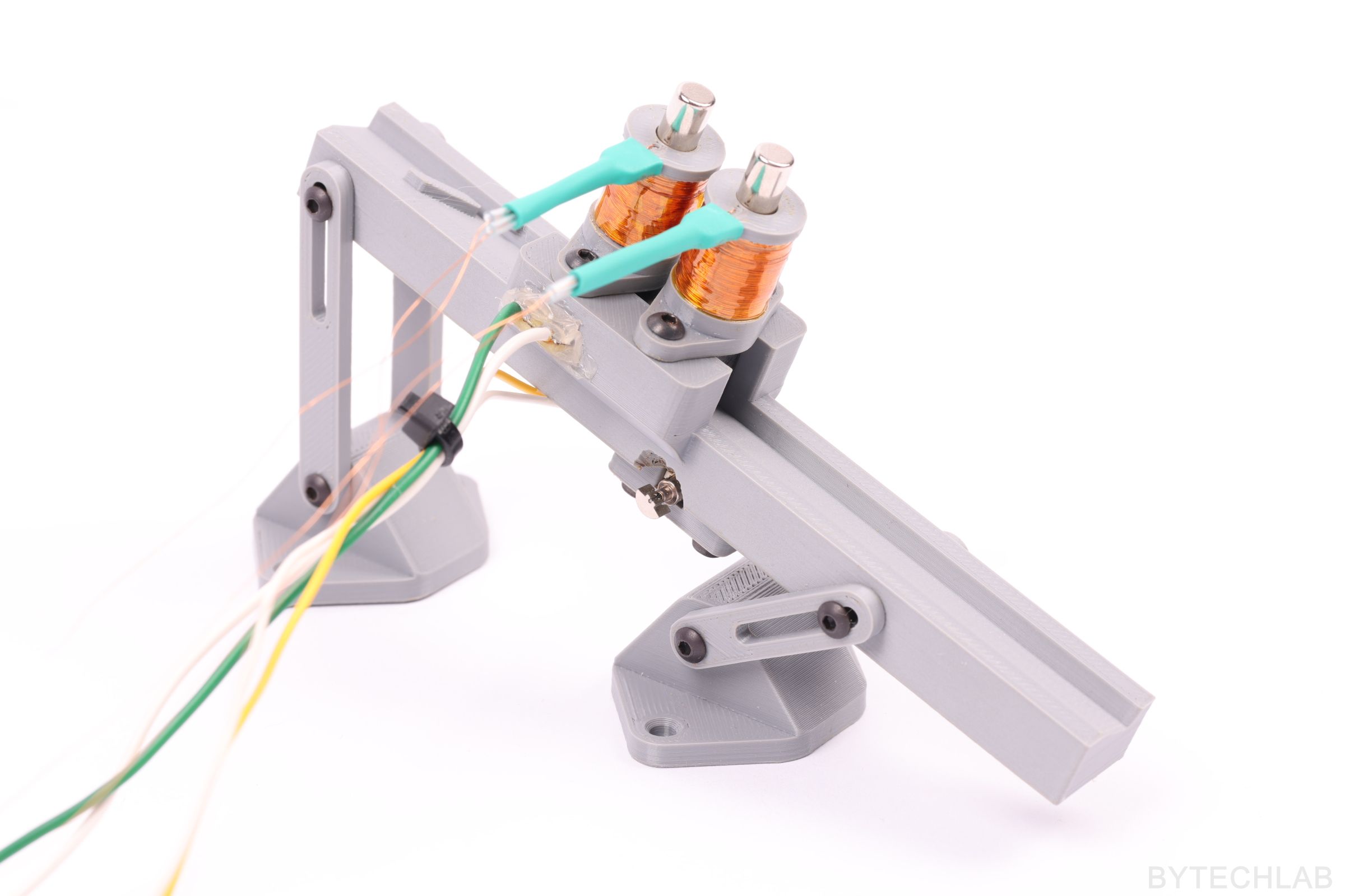
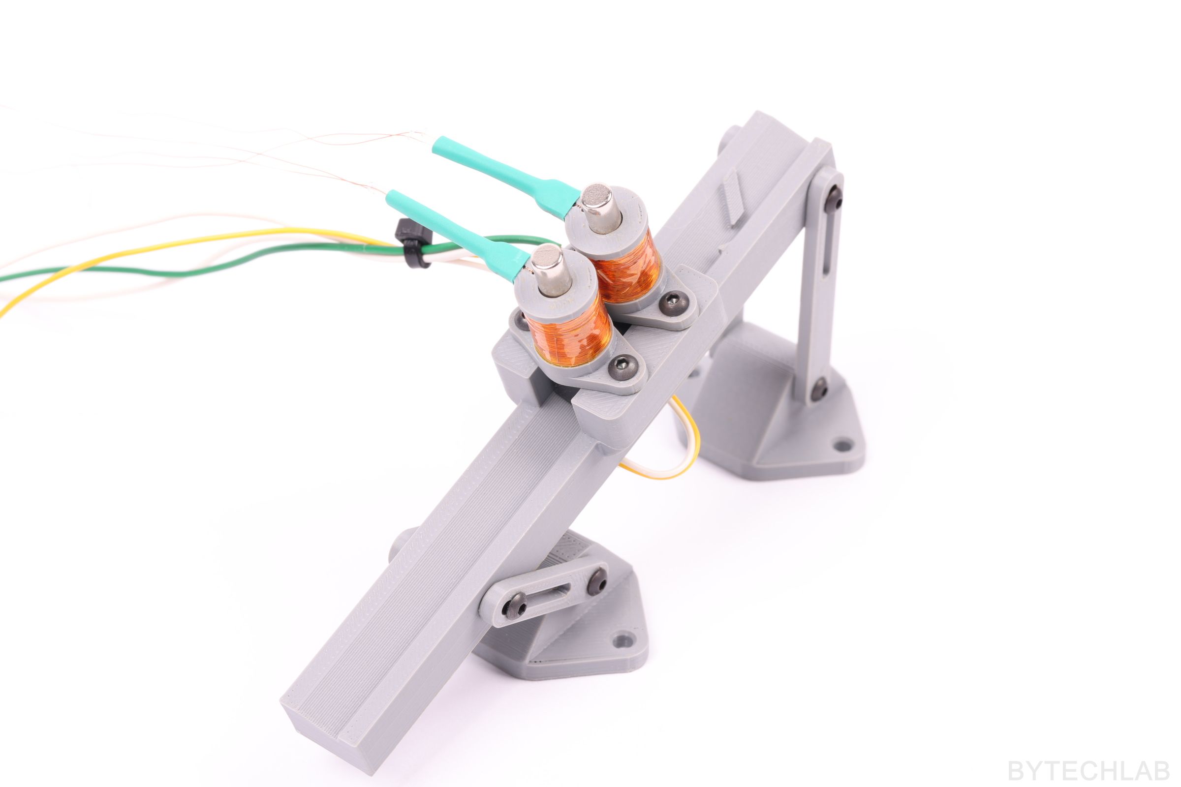
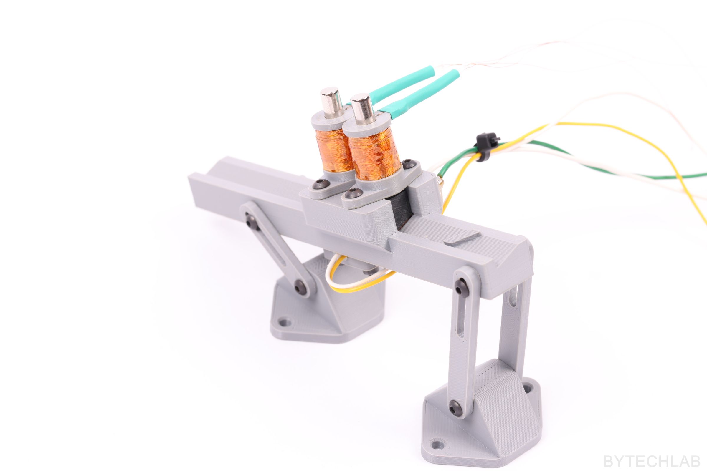
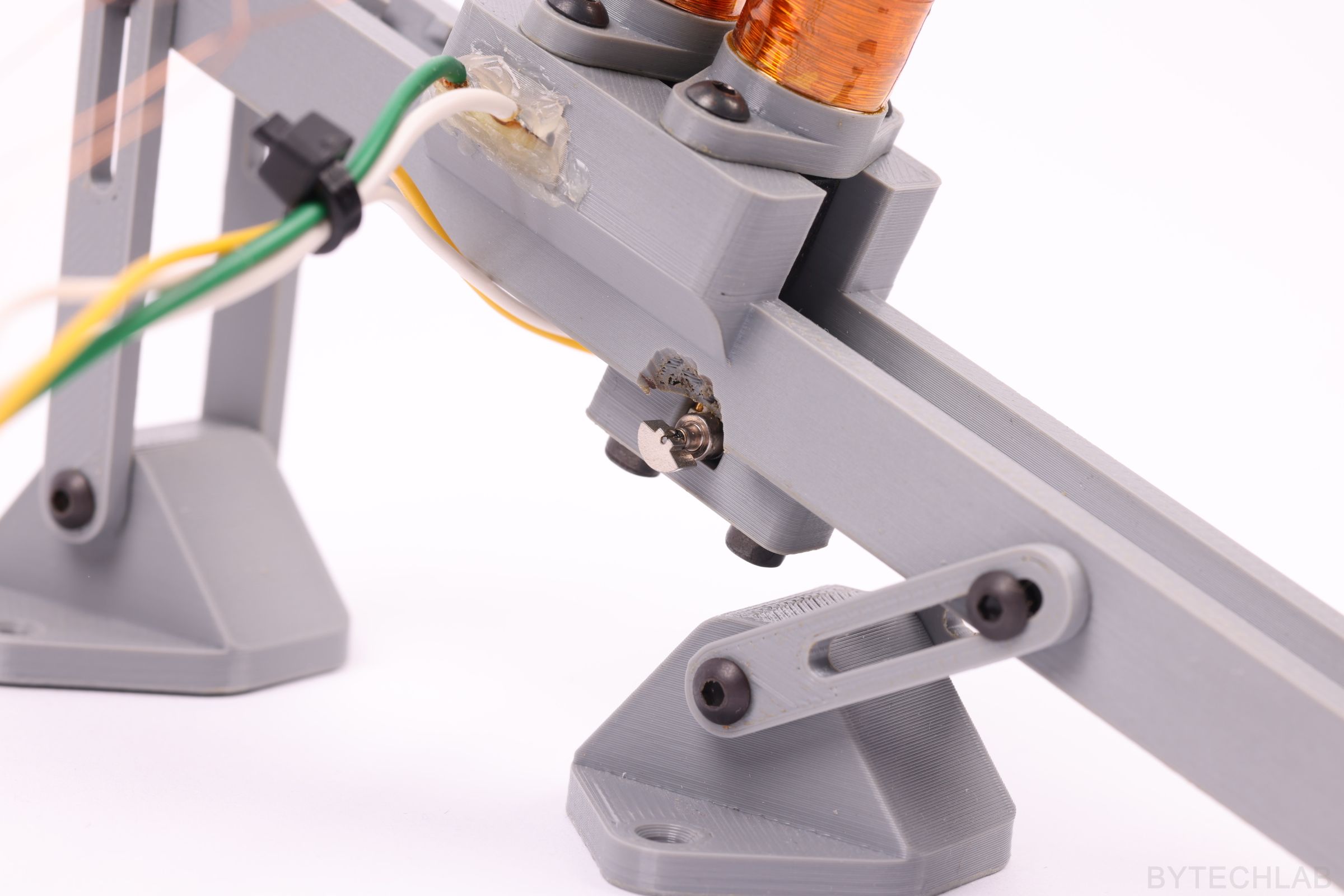
The whole setup will be connected to the rest of the machine through two points: [1] Part inlet and part detection module, [4] part outlet and part detection module. The whole measurement rail angle can be adjusted in wide range to ensure that SMD parts can slide freely on it (this adjustment is accomplished with adjustable legs [7] ). Additionally, a vibration motor [6] is attached to the bottom of the rail to help with the overall movement of the parts.
Just below the part inlet there is an “barrier” and a “flipper” [5] that make sure that the part is in correct orientation just before the measurement. There is also a precise slot to which PCB with measurement contacts slides in [8] . [2] and [3] are solenoid linear actuators (described in one of the previous paragraphs). The first one [2] is responsible for pushing down the SMD part against the contacts to ensure good electrical connection with it. The second one [3] is preventing the part from falling down the rail until the measurement is done.
The whole measurement process proceeds in the following steps:
- Single part falls down to the part detection module from the bowl feeder
- First part detection module [1] senses the part and sends signal to the MCU (Main Controller Unit)
- First linear actuator [2] lifts up and the second one [3] falls down
- MCU turns on the vibration motor [6]
- Part slides through the alignment barrier [5] to the measurement contacts [8]
- MCU turns off the vibration motor [6]
- First linear actuator [2] pushes the part down to the contacts
- Measurement is being taken
- Both linear actuators lift up [2][3]
- MCU turns on the vibration motor [6]
- Part slides down the rail to the outlet
- After it passes second part detection module [4] the whole process repeats again
PART DETECTION MODULES
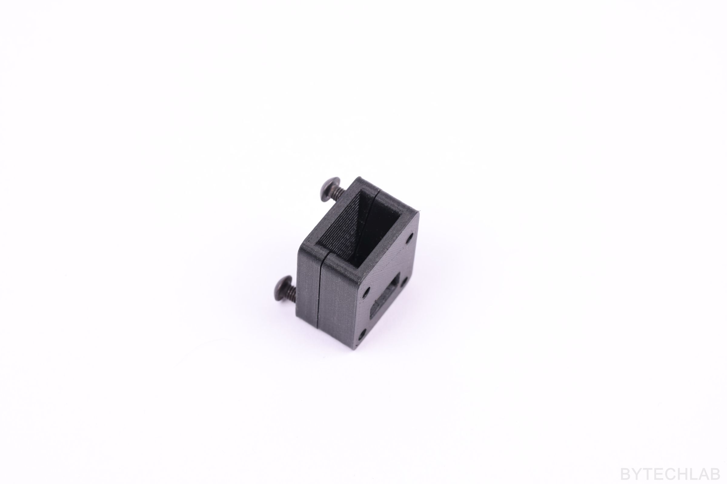
Part detection modules are used to sense the movement of the SMD parts through the whole system. They are important because without them MCU wouldn’t know where the part is at a given moment. They will be used to detect jams in the whole system. One of these modules will be placed under the bowl feeder. Bowl feeder will be turned on and off accordingly to the signal from this module to ensure that only one part falls to the measurement rail at the given moment.
SMD part detector module consists of a two 3D printed halves and a optocoupler sensor. At the top of it there is a embedded funnel that aligns the part just before it enters the optocoupler. When the part cuts off the IR beam a small voltage pulse is being sent to the MCU board. This module can be used also for part counting.

TESTS – VIDEO
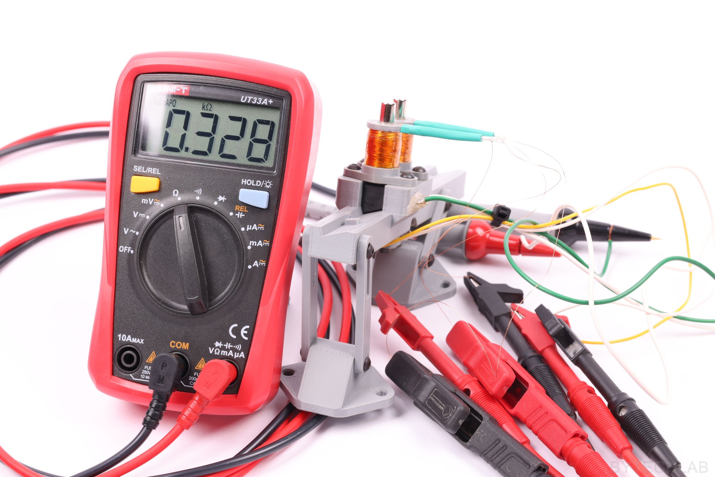
I’ve recorded a short video to help you with understanding how the whole thing works.
MORE PHOTOS

SUMMARY
The Measurement Rail For SMD Parts works quite well, but it still needs some improvements. For example the part is jamming sometimes on the measurement contacts & the solenoid linear actuators have way too much friction inside them ( sometimes the solenoid actuators don’t apply enough force on the SMD parts to take the measurement properly).